NATIONAL MODELLING GUIDELINES WASTEWATER NETWORK MODELLING - Modelling Special Interest Group Draft Version 01 Revision 05 - April 2009
←
→
Page content transcription
If your browser does not render page correctly, please read the page content below
Modelling Special Interest Group

NATIONAL MODELLING GUIDELINES

WASTEWATER NETWORK MODELLING

    Draft Version 01 Revision 05 – April 2009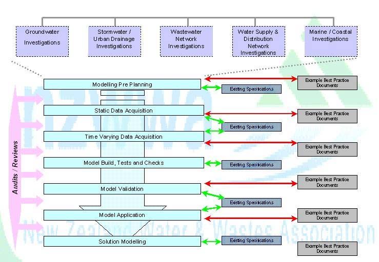
Preface
This document constitutes draft Version 1 Revision 5 of the Water New Zealand
National Guidelines Module 1: Wastewater Modelling Guidelines. Version 1 Revision 4
was published in September 2008. Version 1 Revision 3 was published in June 2004.
Version 1, Revision 2 was reviewed by Water New Zealand. Version 1, Revision 1 was
released for industry consultation in the summer of 2003/2004

Acknowledgments
It is acknowledged that a number of individuals have given up their time and resources
in the production of these guidelines, since their inception in the summer of 2003/2004.
On behalf of the Water New Zealand, Modelling Special Interest Group, their
contribution is recognised and greatly appreciated.

Further information on these draft guidelines is available from:

Water New Zealand
PO Box 1316
Wellington
www.waternz.org.nz

Copyright © Water New Zealand,

Reproduction, adaptation or issuing of this publication for educational or other non-commercial purposes
is authorised without prior permission of the Water New Zealand. Reproduction, adaptation or issuing of
this publication for resale or other commercial purposes is prohibited without the prior permission of Water
New Zealand.

Disclaimer

While the Modelling Special Interest Group of Water New Zealand has prepared these Guidelines in good
faith, exercising all due care and diligence, neither Water New Zealand or individual members of
the Modelling Special Interest Group, or their employers, give any representation or warranty, expressed
or implied, as to the relevance, completeness or fitness of this document in respect of any particular
user’s circumstances. All users of these Guidelines should satisfy themselves concerning its application
to their situation and, where necessary, seek expert advice.
Water New Zealand                                                                          Wastewater Network Modelling Guidelines

Table of Contents
1     Introduction..............................................................................................................4
    1.1    Generic Modelling Process............................................................................................................. 5

2     Initial Planning .........................................................................................................6
    2.1    Key Drivers ..................................................................................................................................... 6
    2.2    Objectives ....................................................................................................................................... 7
    2.3    Model Attributes and Benefits......................................................................................................... 9
    2.4    Data and Other Requirements...................................................................................................... 11
    2.5    Asset Data Requirements............................................................................................................. 12

3     Static Data Acquisition..........................................................................................15
    3.1    General Asset Data ...................................................................................................................... 15
    3.2    Manhole Surveys .......................................................................................................................... 16
    3.3    Pump Station Data........................................................................................................................ 18
    3.4    Operational Data........................................................................................................................... 19
    3.5    Growth (Population) Data ............................................................................................................. 19
    3.6    CCTV Surveys .............................................................................................................................. 20

4     Time Varying Data Acquisition .............................................................................22
    4.1    Flow and Rainfall Surveys ............................................................................................................ 22
    4.2    Implementation ............................................................................................................................. 22

5     Model Build, Test And Check ...............................................................................27
    5.1    Software Selection........................................................................................................................ 27
    5.2    Model Build ................................................................................................................................... 27

6     Model Validation ....................................................................................................30
    6.1    Level of Validation ........................................................................................................................ 30
    6.2    Ground Truth Check ..................................................................................................................... 30
    6.3    Calibration and Verification........................................................................................................... 30

7     Model Application..................................................................................................32
    7.1    Preparation of Existing Model....................................................................................................... 32
    7.2    Preparation of Future Model......................................................................................................... 32
    7.3    Simulations to be Performed ........................................................................................................ 33

8     Solution Modelling.................................................................................................34
    8.1    Define Objectives.......................................................................................................................... 34
    8.2    Test Solutions ...............................................................................................................................34

9     Audit and Review Programme ..............................................................................35
    9.1    Model Project Pre-Planning.......................................................................................................... 35
    9.2    Model Project Static Data Acquisition........................................................................................... 35
    9.3    Model Project Time Varying Data Acquisition .............................................................................. 36
    9.4    Reproduction of Model Results .................................................................................................... 37

10 Project Management..............................................................................................38

11 Modelling Software Support .................................................................................38

12 List of References..................................................................................................39

Version 1 Revision 5                                                       Page 3                                                   April 2009
Water New Zealand                                    Wastewater Network Modelling Guidelines

1 Introduction
         The purpose of these guidelines is to provide good practice protocols for
         undertaking wastewater (sewer) network modelling in New Zealand. In
         establishing these good practice protocols, the guidelines aim to progressively
         improve the development and use of models in New Zealand and consequently
         the accuracy of modelling results so they can be relied upon when undertaking
         developing asset management plans, designing specific engineering solutions
         and assessing environmental effects to support resource consent applications.

         The guidelines contain information and recommended protocols on many
         aspects of wastewater network modelling including: the main types of models
         available and when to use them, the nature of input data required, and how to
         get the most accurate results for the level of assessment required. These
         guidelines have been developed to assist those relatively new to modelling
         techniques, and those involved in scoping and/or reviewing modelling outputs.

         It should be recognised that modelling is a complex process and that some
         training in the form of formal training through workshops or courses is advisable
         before commencing modelling.

         Once the decision to model has been made, these guidelines can help
         practitioners to determine:

         a) which model is most appropriate for the particular circumstances
         b) what data to put into the model (including asset data, flow data and
            meteorological data); and
         c) pitfalls to watch out for.

         These guidelines are not intended to replace formal training or detailed user
         manuals that accompany specific modelling software. In addition it should be
         recognised that the advice provided is not to be taken as an industry or national
         standard.

         The guidelines provide practical advice for all parts of the modelling process
         (Sections 2 to 8) as well as advice on the audit and review process of
         wastewater modelling.

Version 1 Revision 5                        Page 4                           April 2009
Water New Zealand Wastewater Network Modelling Guidelines
1.1 Generic Modelling Process
The generic modelling process is shown on Figure 1 on the following page.
Figure 1: Generic Modelling Process
Version 1 Revision 5 Page 5 April 2009Water New Zealand W
2 Initial Planning
Computer modelling is a complex, specialist task which needs to be
appropriately planned – this ensures that the appropriate outcome will result.
Planning is essential as it assists in identifying tasks to be undertaken, as well
as determining programme, key drivers, objectives to be met, budgets and
justification for the modelling work.
It is recommended that the pre-planning work is undertaken and documented in
the project plan. The project team, particularly the project manager may
subsequently refer to this plan throughout the project.
2.1 Key Drivers
Identifying and understanding the key drivers for the modelling project will assist
scoping and defining the project and the required outcomes. Some of the more
common drivers for New Zealand modelling projects are summarised below.
Table 2.1 – Key Drivers for Modelling Projects
Driver Requirements Components
o Long Term Community o Consultation – Community preferences and priorities
Plan Consultation (LTCCP) o Current status
o Water and Sanitary o Growth planning
Assessments
o Solutions planning
- Options (including non-engineering solutions)
- Costs
- Implementation
o Resource Consents o Manhole discharges
o Assessment of o Pipeline discharges
Environmental Effects o Sludge disposal
(AEE)
o Pump station discharges
o Environmental effects
o Population / growth o Rate of growth
o New development o System performance – existing
o Identify impact on existing o System performance – growth
infrastructure o Identify key bottlenecks – distribution and trunk
system
o Failure analysis. o Likelihood / consequence analysis
o Risk mitigation planning
Version 1 Revision 5 Page 6 April 2009Water New Zealand W
2.2 Objectives
Definition of the objectives of the modelling study is a vital stage in any
modelling project. It enables the best ‘level of modelling’ to be determined,
which will influence the level of investment, project duration and level of
accuracy of the deliverables relative to the desired outcome. The three primary
levels of modelling are defined below.
Version 1 Revision 5 Page 7 April 2009Water New Zealand Wastewater Network Modelling Guidelines
Table 2.2 – Levels of Modelling
Typical Project Objectives Model Type (Level) Example Projects
o Bulk conveyance and treatment options Level 1 - Strategic o Project Storm II (Watercare Services)
o Impact assessment of major regional initiatives o Whole City, o Project Care (North Shore City)
o Waitakere Wastewater Master Plan (Waitakere
o Prioritisation plan for upgrading of catchments, trunk o Large parts of the
City)
mains, major pump stations City,
o Global Model (Metrowater)
o Development of detailed planning and investigation o Significant o Eastern Suburbs Model (Manukau Water)
programmes catchments o Christchurch City Council
o Scenario development, assessment and costing for
consultation purposes
o 20-50 year cost estimates for upgrading programmes
o Identification of high risk assets
o Operational performance assessment Level 2 - Catchment o Joint Catchment Studies (Watercare and
o Establish cause of flooding/overflows o Catchment Metrowater)
management o Waitakere City Council - New Lynn Modelling and
o I/I control programming
I/I Investigations
o Localised growth scenario planning o Single large o North Shore City studies
o RMA compliance assessment and monitoring catchments o Manukau Water studies
o Pump station upgrading options o Adjoining o Metrowater Catchment Improvement Projects
o Inter catchment transfers assessment catchments (CIPs)
o Improving level of services o Small parts of city o Christchurch City Council
o Long term upgrading programme development
Version 1 Revision 5 Page 8 April 2009Water New Zealand Wastewater Network Modelling Guidelines
2.3 Model Attributes and Benefits
Table 2.3 – Level 1 Strategic Model Attributes
Typical Objectives Typical Outputs Typical Benefits Model Complexity
o Bulk conveyance and treatment o Hydraulic impacts of significant o Framework for more detailed o Can vary from simple static type
options trade waste sources studies models (inexpensive) to simple
o Impact assessment of major o Treatment location options o Prioritisation of future expenditure dynamic models (more
regional initiatives o Forward planning programmes o Assists with consultation expensive)
o Prioritisation plan for upgrading of Simple static models can be done
- Prioritised catchments o Better understanding of future o
catchments, trunk mains, major upgrade programme in-house on spreadsheet or with
works programmes
pump stations - Prioritised treatment upgrade simple hydraulic software
o Development of detailed planning o Inputs to Asset Management
programme Plan, LTCCP, Water Assessment o The more complex simple
and investigation programmes - Prioritised trunk main upgrade dynamic models may be beyond
o Scenario development, o Least expensive
programme the capability of in-house
assessment and costing for - Prioritised pump station o Relatively short timeframe to resources – does require
consultation purposes upgrade programme complete modelling experience
o 20-50 year cost estimates for - Detailed planning programme o Lower requirements in terms of
upgrading programmes - New asset construction asset data coverage and quality
o Identification of high risk assets programme
o High level assessment of large or
o Cost projections for 20-50% for
significant catchments
new infrastructure and upgrades
o High level impact of any
significant proposed development o Consultation planning
initiatives documentation
Version 1 Revision 5 Page 9 April 2009Water New Zealand Wastewater Network Modelling Guidelines
Table 2.4 – Level 2 Catchment Model Attributes
Typical Objectives Typical Outputs Typical Benefits Model Complexity
o Operational Performance o Upgrading strategy o Linkage with renewal planning o Medium to high level complexity
Assessment and optimisation - Long term upgrading and prioritisation of renewals requiring sophisticated software
o Establish cause of flooding / programme for treatment, programmes that makes use of time varying
overflows pipes, pump stations (costs o Improved confidence level in data to generate a dynamic
o I/I control programming and scope) outputs for cost, nature and model
o Localised treatment options - Mini-catchment prioritisation extent of works o Requires fairly extensive asset
analysis for I/I control programme data of good quality
o Confirmation of operational
o Localised growth scenario - Overflow containment, problems and identification of o Requires experienced modellers
planning treatment and monitoring previously unknown operational with good understanding of
o RMA compliance assessment strategy problems (e.g. manhole engineering problems and
and monitoring o New Infrastructure Planning discharges) solutions
o Pump station upgrading options
o Continual o Base model for more detailed o External peer reviews advisable
o Inter catchment transfers
improvement/monitoring studies at key stages of project (typically
assessment
programme o Base model for monitoring of model build; calibration; system
o System optimisation for known
rate of growth o Improved asset inventory trends or net impact of network performance)
o Improving level of service for no o Effluent quality assessment improvements o Future use requires experienced
growth - Effluent characterisation at o Problem prioritisation – enables in-house resources data
o Long term upgrading programme any point in network – wet and funds to be targeted at areas of management systems,
development dry weather specific and urgent need investment in software and
o Environmental impact - Hydrographs and quality o Quantification of effluent training
assessment of discharges to graphs to support design discharge volumes/quality
environment o Detailed designs
o Calibration of model against
o Impact assessment of any - Upgrades for new
measured performance gives
significant proposed development developments
increased confidence in model
initiatives - Optimisation of pump station
output
o Support detailed design operation
- Containment structures
- Discharge treatment
structures
Version 1 Revision 5 Page 10 April 2009Water New Zealand Wastewater Network Modelling Guidelines
2.4 Data and Other Requirements
2.4.1 Model Extents
Regardless of the level of model selected, it is necessary to define the model
limits (or extents of the model) and the key points in the network for which
information is required.
Model extents are typically defined by the data collected:
a) Pipe diameter (e.g. pipes smaller than 225mm diameters not modelled)
b) Location of known operational problems (e.g. flooding; manhole overflows;
regular silt build-up)
c) Location of critical assets (pump stations, river crossings, major road
crossings, estuary crossings, treatment plant etc)
d) Location of planned significant regional initiatives
e) Location of planned significant localised development initiatives
f) Location of known operational devices (cross-connections; controlled
overflow points; storage tanks; treatment devices)
Key points in the network can comprise points where the flows and depths
should be accurately modelled, where problems are known to occur or where
problems could arise in the future.
All these points the network should be accurately represented in the model.
Typical examples could include:
a) Manholes with treatment or containment devices; controlled overflow
devices (e.g. weirs); known surcharging or discharging problems; cross
connections to other manholes in the network
b) Hydraulic boundary constraints such as pump stations; manholes as above,
connections to large bulk conveyance systems
c) Low lying public areas where discharges could result in a public health
hazard
It should be noted however that the level of accuracy required should be
commensurate with the required outcome from the model and it could be
appropriate not to include some key points explicitly in the model, in say a Level
1 model.
Version 1 Revision 5 Page 11 April 2009Water New Zealand Wastewater Network Modelling Guidelines
2.5 Asset Data Requirements
Table 2.5 – Level 1 Strategic Model Data Requirements
Level 1 Model – Strategic Planning
Data Description
Source Accuracy Condition Detail
Manholes o GIS o Contour plans o Lid levels, internal dimensions / volumes
o As-built plans (1m) o Controlled overflow devices such as
o Operational staff o 0.2m, survey if weirs, pipes
o Complaints database necessary o Uncontrolled overflows at manholes, via
lid
Pipelines o GIS Off GIS or as-built o Known operational problems o Diameter, length (typically exclude pipes
o Coverage to suit model plans such as roots, debris, fat, low smaller than Ø225mm)
limits Data validate only gradients o Material
o Hydraulic textbooks o Regular maintenance o Gradients
o Design standards requirements o Levels
o Material o Pipe roughness
Pump stations o GIS As-built plans o Operational issues o Pump delivery rate
o Pump station database o Maintenance programme o Pump delivery head
o As-built plans o Storage
o Rising main details
Containment o GIS As-built plans o Operational issues o Levels
devices o As-built plans o Maintenance programme o Capacity
Catchment o GIS o 1: 50000 scale o N/A o “Watershed” boundary line
boundary o Contour plans plan
Growth projections o In-house projections o Mesh block o Latest available estimates o Population
o Census data level o Regional developments
o Localised development initiatives
Known operational o Operational staff o Location pin o Frequency and consequence o Hydraulic Bottlenecks
problems o Significant problems pointed established during discussion o Discharges
only o Historical flooding
Flow and rainfall o Permanent monitors o Time varying flow and rainfall data
surveys (simple and rain gauges o Data validate
dynamic model o Short term survey o Sample check
only) o Pump station flow
meters
Version 1 Revision 5 Page 12 April 2009Water New Zealand Wastewater Network Modelling Guidelines
Table 2.6 – Level 2 Catchment Model Data Requirements
Data Level 2 Model – Catchment Management Planning
Description Source Accuracy Condition/Other Detail
Manholes o GIS o As-built drawings or GIS o Inlet/outlet invert levels o Lid levels (lidar surveys)
o Field survey = 0.1m o Pipe length o Invert level at centre of manhole
o As-built plans o Survey where data is o Pipe diameter o Levels, internal dimensions / volumes
missing o Data validate / Sample check
o Operational staff o Survey where data is o Establish nature of o Controlled overflow devices such as
o Complaints database missing receiving environment weirs, pipes
(parks, property, riparian o Data validate
margin etc) o Uncontrolled overflows at manholes, via
lid
Pipelines o GIS o Off GIS or as-built plans o Known operational
o Diameter, length
o Coverage to suit o Survey where data is problems such as roots, o Material
model limits missing for key debris, fat, low gradients o Length
o Hydraulic textbooks components o Regular maintenanceo Gradients
o Design standards requirements o Levels
o Site survey o Review CCTV for key o Data validate and
components o Sample check
o Pipe roughness
Pump stations o GIS o Measure key elevations o Known operational o Pump delivery rate
o Pump station o Measure key problems o Pump delivery head
database dimensions of wet well o Maintenance programme o Storage
o As-built plans o Confirm all operational o Confirm system operation o Rising main details
o Site survey levels design o Telemetry records
o Flow meter records
Containment o GIS o Measure key dimension o Known operational o Level data
devices o As-built plans of structure problems o Tank dimensions
o Site survey o Measure key elevations o Maintenance programme o Outlet details
(inlet, outlet, overflow) o Overflow details
o Confirm overflow details o Sample check
Version 1 Revision 5 Page 13 April 2009Water New Zealand Wastewater Network Modelling Guidelines
Data Level 2 Model – Catchment Management Planning
Description Source Accuracy Condition/Other Detail
Catchment o GIS o 1: 5000 scale plan o N/A o “Watershed” boundary line
boundary o Contour plans o Review connectivity
o plans
Known o Operational staff o Location pin pointed o Frequency and o Hydraulic Bottlenecks
operational o Significant problems o Accurate survey and consequence established o Discharges
problems only measurement during discussion o Historic flooding sites
o CCTV where
appropriate
Flow and rainfall o Short term survey (6- o Dry weather flow o The quality of data will o Location of monitors
surveys 12 weeks) information required have a big impact on o Type of monitors
o Permanent flow and o Min 3 x significant wet outcome of study. Since o Raw and final (edited) data
rain gauges events required the outcome could involve o Data to be as recent as possible
o Pump station flow o Good quality reliable $m’s, it is important that o Independent data audit (completed
meters data required good quality data is during survey)
obtained
Assessment of o Independent study o Effect on receiving environment
environmental o Effluent quality/load
effects o Assessment of “first flush”
Version 1 Revision 5 Page 14 April 2009Water New Zealand Wastewater Network Modelling Guidelines
3 Static Data Acquisition
3.1 General Asset Data
General asset data is data that will typically be held on a GIS system or other
database or as-built plans and which is readily available for use in a model. It
often serves as the base data for the building of any model. It is important to
focus on gathering (and improving where necessary) that data sets that are
important to achieve a ‘fit for purpose’ outcome, not necessarily those data sets
which are interesting.
Typically this data will include:
a) GIS system data
i. aerial photographs
ii. contours
iii. catchment boundaries
iv. roads
v. cadastral
vi. population mesh blocks
vii. connectivity
viii. land use
ix. impermeable area data
x. soil data (if available)
b) Assets (pipes, manholes, pump stations, etc) and associated attributes
(levels, grades, diameters, etc)
c) Pipe and manhole connectivity data, boundary conditions and configurations
at hydraulic control points such as pump stations; bulk conveyance systems
operated by others.
d) Design data associated with pump stations (inlet level(s); pump level; pump
stop/start levels; pump performance curves; rising main system curves; wet
well dimensions; overflow pipe details and levels)
e) Design data associated with various hydraulic features such as temporary
storage tanks, weirs, screens, controlled overflow points
f) Water consumption data (at property level if available, otherwise from bulk
meters but will require water supply zone details to be of any use). Large
consumers need to be identified. Diurnal flow patters will be useful if these
are available.
3.1.1 Data Validation
The data should be validated where possible to identify and confirm:
a) up-sloping (negative) pipe gradients
b) pipe diameters that reduce in the direction of the flow
c) data attributes (such as levels, pipe lengths, pipe diameter, pipe materials,
asset age, pump performance curves)
d) pipe connectivity
e) catchment boundaries
Version 1 Revision 5 Page 15 April 2009Water New Zealand Wastewater Network Modelling Guidelines
The extent and quality of the asset data required for the model is dependent
upon the Level of Modelling required (e.g. a Level 1 Strategic Model or a Level
2 Catchment Model).
3.1.2 Data Prioritisation
Having completed the data validation check, it should be possible to generate a
Missing Data Report that will identify all missing asset data, highlight key
missing data and provide a prioritised list of data to be collected for the model.
It is suggested that a system for prioritising data capture be adopted as follows:
Top Priority - Essential for the building of the model
Such data is likely to be a key node in the model system and every effort
should be expended to obtain this data. Other examples could include
checking connectivity and catchment boundaries anomalies.
Medium Priority - Important for the building of the model
Such data will be of assistance in the simplification process in the building
of a model and could include manhole elevations, pipe diameter
confirmation, CCTV of pipes with flat gradients (to assess silt build up).
Lower Priority - Non essential data (but nice to have)
Such information may help fine tune and improve the model performance
but is generally beyond the level of detail required for the level of
modelling selected. Also, it will not have a significant impact on the model
hydraulics. An example is collection of missing manhole elevation data for
manholes that may not be utilised in the model because of the
simplification process followed in the building of the model.
3.2 Manhole Surveys
The primary purpose of manhole surveys is to gather missing information that is
required for the building of the model. However, when visiting the site of a
manhole, it is economical to collect (or confirm) as much information as possible
about the manhole including condition information, location sketch (if difficult to
find), and digital photograph showing its location.
A manhole survey will normally focus on a catchment and could involve a few
manholes to hundreds of manholes depending on the extent of the catchment,
the quality of records held by the authority and the desired outcome of the
study. Generally the more manholes that have to be visited, the more effort
there is to setting up the project. Typically the scope of works will involve:
Version 1 Revision 5 Page 16 April 2009Water New Zealand Wastewater Network Modelling Guidelines
3.2.1 Project Set-up
a) Preparation of plans (with aerial back drop if possible) showing manholes to
be visited, network layout and also layout of any other networks with
manholes (e.g. stormwater).
b) Preparation of spreadsheet with relevant known manhole details (manhole
number, street address, lid level, inverts level, etc) and with columns for
unknown data.
c) Preparation of manhole inspection sheets.
d) Development of protocols for dealing with different scenarios such as:
i. Manholes with “frozen” lids
ii. Buried manholes
iii. Manholes posing an immediate health and safety risk (e.g. missing
lids; manhole about to collapse, etc)
iv. Manholes with significant defects that require urgent attention (e.g.
severe root intrusion; severe infiltration; structural problems)
v. Manholes with minor defects
vi. Manholes that cannot be located
vii. New manholes not shown on the drawings
viii. Illegal connections
e) Advance notification of property owners. The objective here is to keep
owners / tenants informed of the survey (and of unknown workers wandering
around in their backyards) and to identify any access problems such as
locked gates or guard dogs.
3.2.2 Implementation
This can be undertaken using in-house resources (especially if the operator
owns a maintenance company) or by contract. Regardless of who carries out
the work, it is necessary to have a “client-side” project manager who can deal
with any owner/tenant complaints, co-ordinate actions arising out of the survey
(e.g. fix manhole urgently) and make arrangements for manholes to be located
if these are buried (e.g. by way of CCTV). Generally the implementation phase
will include:
a) Manhole location
b) Manhole inspection (condition; collect data on connecting pipes (diameter,
level, house serviced, etc))
c) Survey of lid levels, measurement of depth, XYZ (if applicable)
d) Digital photographs showing location of manhole; manhole interior
e) Documentation of results
f) Independent data review (audit) and accuracy check
3.2.3 Close-out
The survey will generate a lot of new data on the assets and the “client-side”
project manager should ensure that this is captured on the appropriate
database systems (e.g. Hanson; GIS; spreadsheets) for future use and record.
The project manager will need to make sure that all buried manholes are raised
Version 1 Revision 5 Page 17 April 2009Water New Zealand Wastewater Network Modelling Guidelines
and that defects are recorded on maintenance register for immediate or future
action. An audit of a small percentage of the data collected is recommended.
3.3 Pump Station Data
Pump stations are hydraulic control points in wastewater systems. Since pump
stations usually include some form of storage, the effect can be a discontinuity
in flow with either positive or negative downstream effects depending upon
whether the pumps are operating during peak flow or low flow conditions.
It can also be difficult to integrate the pump station into the model such that the
model outputs accurately reflect reality. The better and more comprehensive
the information is about the pump station, the more accurately the model can
mirror the operation and performance of the pump station.
Ideally, during the verification stage of the model (when its outputs are being
compared with reality – i.e. known circumstances and performance) an
indication of the performance of the pump station is essential. When possible
draw-down testing should be carried out for all pumps singly and in
combination. These can be supplemented by flow gauge and pressure gauge
readings if such devices are available.
Other essential information that will be required by the modeller will include:
a) Location plan
b) Elevations and sections
c) Pipe work configuration and fittings
d) Operational parameters (e.g. pump stop/start; alarms; pump duty/standby
switching; dealing with overflows)
e) Catchment size
f) Available information from telemetry or other records
g) Number, type and configuration of pumps
h) Pump and/or system performance curves / design characteristics
i) Elevations (especially stop/start; centre of impellor; discharge point; highest
point in rising main – if higher than discharge point)
j) Rising main material, age, diameter, length (and horizontal and vertical
alignment if available)
k) Overflow weir details
l) Maintenance details such as frequency of de-silting; pump clogging;
recurrent problems of a specific nature.
Version 1 Revision 5 Page 18 April 2009Water New Zealand Wastewater Network Modelling Guidelines
3.4 Operational Data
Operational records are an important source of information since they enable
the output from the model to be verified and can assist the modeller in
determining where any discrepancies are. Operations staff play a key role in
the dissemination of this information and should be involved throughout the
model building and verification process.
Typically, operational records should provide the following information:
a) Manhole spills, frequency and cause
b) Blockages; and cause (e.g. fat build-up; root infestation; pipe collapse)
c) Spot repairs
d) Stormwater flooding (which can manifest itself in the form of illegal
stormwater connections to the wastewater network)
e) Rainfall data from rain gauges
f) Flow data from long term flow monitors
The information can be augmented by the hands-on experience of operational
staff who are often able to draw attention to undocumented operational
problems (e.g. pipeline in an unstable zone where movement is occurring),
undocumented changes to the system (new pipelines; deviations; new
manholes; changed pumps; changed operational procedures that impact on
flows), problem areas from a maintenance perspective (frequent manhole spills
or blockages; flat gradients; silt / fat deposits), regular preventative maintenance
activities (e.g. flushing of pipelines), confirmation of trade waste flows (location
and magnitude), location of undocumented controlled overflow points, known
bottleneck points.
Operational staff can also contribute to solving system problems
3.5 Growth (Population) Data
Growth data is essential for modelling future demands and typically consists of
the following factors.
3.5.1 Existing Urban Environment
Population data is available from NZ Statistics. This data does indicate trends
that can be used in projecting future populations. However, local authority
planners should be able to provide more accurate projections based on known
planning constraints. In the Auckland region, for example, most authorities
have projections for their cities and these are at mesh block level for the next 20
years and at a catchment level for the next 50 years. In smaller cities or towns,
where perhaps densification is not an issue, then assumptions will need to be
made on future growth projections.
3.5.2 New Urban Environments (Greenfields)
Greenfield sites that are planned for within and adjacent to existing catchments
may be developed in the future is useful information for modelling projects.
Version 1 Revision 5 Page 19 April 2009Water New Zealand Wastewater Network Modelling Guidelines
Where large-scale development is expected within the next 20 years then an
estimate has to be made of:
a) location and sequencing (timing) of such development
b) expected housing density and associated population
c) expected commercial/industrial growth and consumption
Again, this information may be in the hands of the authorities’ planners but,
failing this, assumptions will have to be made and be clearly stated.
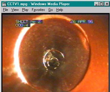
3.6 CCTV Surveys
CCTV data is a ‘nice to have’ data set and is not normally essential for the
majority of modelling projects. A CCTV survey is normally required to:
a) Confirm connectivity
b) Confirm live/dead status of pipelines
c) Confirm pipeline material/diameter
d) Assess silt build up levels
e) Identify the presence of hydraulic chokes (root intrusions; protruding laterals;
debris; fatty deposits; etc) that could cause discrepancies between the
modelled results and historical records (e.g. overflows at manholes)
f) Confirm stormwater cross-connections
Like the manhole surveys, a CCTV survey will generally require entry to private
property and could cause concern to owners/tenants of properties. It is prudent
to give such people advance notice and to establish potential entry constraints
such as locked gates and dogs.
These surveys are best undertaken by companies specialising in CCTV
inspections, and be conducted in general accordance with the NZ Pipeline
Inspection Manual. It should be noted that this manual does require an element
of forethought by the specifying authority, especially in respect of the delivery
formats of the data to be collected.
Also, since access to a section of pipeline to be surveyed is normally via a
manhole, it is also prudent to allow for a manhole condition inspection at the
time a manhole is opened. Other data such as connections, depth could also
be collected at the same time.
Client-side project management is required to respond to on-site problems (e.g.
clearing of blockages), deal with owner/tenant complaints, audit (or arrange for
audit) of videos and project close-out (capture of information on database
systems; dissemination of information to the modeller, etc).
3.6.1 Water Consumption Data
This data set is a ‘nice to have’ and is not essential for most modelling projects.
Some authorities aim to reduce the average water consumption by introducing
demand management strategies. This will have a corresponding impact on
Version 1 Revision 5 Page 20 April 2009Water New Zealand Wastewater Network Modelling Guidelines
wastewater flow and will need to be considered. Water demand in New Zealand
urban areas typically ranges between 150 and 200 litres per person per day,
and corresponding wastewater flows are typically 200 to 300 litres per person
per day depending on the levels of infiltration (ground water ingress) observed
by the wastewater network.
Since the growth data will have an enormous impact on the configuration,
extent and capacity of the future wastewater system (as well as the expenditure
of funds to get there), it is important that the authority retains responsibility for
developing the growth data. This should not preclude the use of consultants but
does mean that a high level of input/management is required of the authority
especially in respect of the assumptions that are made. Generally this process
will require inputs from strategic planners; asset engineers and possibly even
developers, especially if there are some large developments proposed in the
short term (say within the upcoming five years). A “client-side” project manager
can play an important role in co-ordinating the various stakeholders, maintaining
focus and ensuring timely delivery.
Version 1 Revision 5 Page 21 April 2009Water New Zealand Wastewater Network Modelling Guidelines
4 Time Varying Data Acquisition
Time varying data such as flow and rainfall surveys are a complex and difficult
component of the modelling project to manage. There is often a large number of
staff involved for this work, across multiple companies which further adds to the
complexity. As a significant portion of this work is performed underground,
detailed pre-planning, support systems such as health and safely practices, and
effective communications between all parties are crucial in ensuring these
surveys are completed, well and without incident.
4.1 Flow and Rainfall Surveys
Even with separated wastewater and stormwater systems, wet weather can
have a dramatic impact on the flow in the wastewater system. This is because
of inflow and infiltration sources, which enable stormwater to gain access into
the wastewater systems, substantially increasing flows and often resulting in the
overloading of the system, and spills at manholes.
Inflow is generally via direct stormwater connections to the wastewater system
(generally illegal and undocumented) such as Stormwater down pipe
connections, low lying or defective private gulley-traps, cracked or defective
manholes in low lying positions susceptible to flooding. The impact of inflow is
generally fast (often referred to as fast-response) and also ceases relatively
quickly following the cessation of a storm (depending of course on whether the
inflow source is located in a flooded area, in which case the inflow will continue
until the supply is exhausted).
Infiltration is generally related to the condition of the wastewater system, the
nature of the soil and the antecedent moisture content of the soil. It is
essentially the infiltration of groundwater into the system via cracks and other
sub-surface defects. The impact of infiltration can take some time to mobilise
(often referred to as slow response) and can continue for some time (often
days) after a rainfall event.
The aim of flow and rainfall surveys is to establish the relationship between
flows in the wastewater system and rainfall events. Such surveys will also
provide information on base flows (flow in system during periods of low or “zero”
demand) and diurnal flow characteristics during dry and wet weather. Long-
term (often permanently) flow survey programmes will also provide information
on seasonal variances in flow patterns and on growth trends in the flow.
4.2 Implementation
A flow and rainfall survey is generally an expensive undertaking since it requires
a high degree of technical skill and input as well as regular (at least weekly for
short term surveys) maintenance of the gauges. As a result, flow and rainfall
surveys for the purpose of modelling are commonly, but not always short term
(6-12 weeks) occurring preferably during the wet season when the probability
and frequency of encountering significant rainfall events is at its highest. In
some cases long term flow gauging is carried out to understand the variations in
flow which occur over a long period of time, this will greatly enhance the quality
Version 1 Revision 5 Page 22 April 2009Water New Zealand Wastewater Network Modelling Guidelines
of the model produced and the decision to commit to a long term flow gauging
survey must be balanced against the cost of procuring one.
There are a number of stages in the implementation of a flow and rainfall survey
and these are discussed below:
4.2.1 Gauging Network Design
The aim of this is to develop a robust layout for rain and flow gauges and
involves:
a) Desk top study to establish any existing gauges (generally rain gauges,
pump station flow records) and availability/suitability of associated data;
b) assess system layout and topography to determine best spread of rain
gauges;
c) assess known problem areas in the system and select suitable sites to
cover these;
d) assess the preferred location of gauges in the wastewater system and
eliminate those with poor hydraulic criteria (e.g. potential turbulence,
susceptibility to surcharging etc);
e) assess possible alternative sites for each selected site (two or more if
possible);
f) establish what sites are located in assets belonging to other authorities
(e.g. a bulk collection authority) and whether these have any objection to
the use of their assets as a gauging site (note – in such cases it is also
necessary to establish any operational issues such as flushing
programmes that need to be taken account of during the survey period).
Some broad guidelines for the selection of flow gauging sites include:
d) Monitor any branches that are entering from outside the catchment being
monitored
e) Maximise the number of “leaf” gauge catchments (conversely minimise the
number of “subtract” gauge catchments). A “leaf" catchment is a standalone
catchment with no upstream inflows from adjoining gauge catchments. This
is to reduce subtraction errors of one gauge flow to another.
f) Length of public wastewater pipelines in each gauge catchment –
approximately three kilometres.
g) Dry weather flow depth for “HVQ” gauge ≥ 40 mm. Otherwise use a v-notch
weir gauge as an alternative as these gauges provide better resolution of
flow for slower and shallower flow depths.
h) Dry weather flow rate for “HVQ” gauge ≥ 0.3m/s.
i) Gradient of pipeline in which gauge installed ≤ 2%.
j) There should be no sudden hydraulic transitions at gauge sites (e.g. service
lateral adjacent to gauge; major conveyance of pipelines at gauge manhole;
drop connections into manhole; abrupt change in direction or gradient at
manhole; imperfections in pipeline or manhole channelling).
k) Monitor locations of known existing problems
Version 1 Revision 5 Page 23 April 2009Water New Zealand Wastewater Network Modelling Guidelines
l) Controlled overflow points at manholes should be monitored.
m) The size of the selected gauging network should be appropriate to the level
of modelling detail required and the desired outcome from the investigation.
Public Communications
Many of the flow and rain gauge sites will be located on private property. The
survey process will involve multiple visits of varied duration and timing to each
site and there is potential to disturb or annoy owners/tenants. However, during
the gauge network design stage, a single visit to the site is generally sufficient.
Consequently, it should only be necessary to advise owners/tenants of the
proposed inspection (giving some background information and purpose of the
flow and rainfall survey) and obtain any constraints to access such as locked
gates and dogs. This should be undertaken at least a week in advance of any
proposed inspections to give owners/tenants time to respond. The client-side
project manager is generally the best contract person for this and should
document any owner concerns or access constraints and manage the issues.
Field check of Proposed Gauge Sites
It is best to confirm the suitability of the selected gauge sites well in advance of
letting a flow and rainfall survey. This will allow time for adjustments to the
gauging network (and these can occasionally be substantial adjustments) and
minimise the risk of delays or associated claims from the flow-gauging
contractor. It also enables the scope of the flow and rainfall survey contract to
be clearly defined.
Flow gauging contractors will happily assist with the inspection of flow gauging
sites (at a cost of course).
The aim of the field check is to confirm the suitability of each of the selected
gauge sites. The desk study may have identified two or three possible locations
for each site and each of these should be inspected and rated against each
other. Where none of these is suitable, then the modeller may need to
reconsider his layout and develop alternative proposals.
Photos and sketches should be made of each site inspected.
Gauge Network Report
Following the field check of sites, a gauge network report should be compiled
giving the following information:
a) Overall location plan (flow gauge sites).
b) Overall location plan (rain gauge sites).
c) Table of flow gauge details (site identification number, site manhole number,
physical address of site, length of upstream pipeline (site specific and
accumulative), population served (site specific and accumulative), expected
dry weather flows and associated depth of flow; preferred type of gauge
(HVQ/weir); pipeline diameter; “subtract” or “leaf” gauge).
Version 1 Revision 5 Page 24 April 2009Water New Zealand Wastewater Network Modelling Guidelines
d) Table of rain gauge details (site identification number; physical address of
site; whether existing or not).
e) Description of each gauge site (accessibility, flow regime at time of
inspection, comments on suitability etc). This would include a completed
sketch giving various details on the site such as manhole configuration,
proposed location of gauge within manhole; direction of flow.
f) Any assumptions made.
g) Reasons for selection of the sites.
4.2.2 Flow and Rainfall Survey
The duration of the survey should be selected on the basis of when it will take
place, the use to which the information will be put (modelling; infiltration/inflow
studies or other) and the likelihood that the required number of significant
rainfall events will take place during the survey.
Because frequent access to the gauge site will be required during the survey
period, it is usually prudent to serve notice to the owners/tenants of properties
where sites are located. This should be undertaken prior to seeking tenders for
the flow and rainfall survey.
Flow and rainfall gauging is extremely specialised work requiring very
experienced and skilled technical staff. The information collected underpins the
recommendations or outcome of any modelling study, which could subsequently
result in the capital expenditure decisions. It is therefore imperative that the
data collected is of the best quality possible. It is recommended that early
involvement of an independent reviewer (auditor) is planned for with any flow
survey. Data should be downloaded from the flow contactor on a weekly basis
and checked as ‘fit for purpose’. The frequency of these checks can be reduced
to fortnightly once there is a level of confidence in the data being collected and
the gauging sites are producing good clarity of data profiles. The quality of the
final edited data can be highly variable as a result and it is strongly advised that
an experienced and independent auditor be appointed in advance of the award
of any flow and rainfall survey contract in order to:
a) Review the specifications
b) Become familiar with the project
c) Assist with the evaluation of tenders (especially in respect of technical
issues and data formats)
d) Supervise the flow and rainfall gauging contractor
e) Review the regular reports by the contractor
f) Audit the data collected by the contractor
The role of the client, or the client-side project manager in the implementation of
the flow and rainfall survey should not be under-estimated. It may include:
a) Procurement of services (modeller, auditor, flow gauging contractor)
b) Owner consent process and dealing with related problems
c) Co-ordination of auditor and flow gauging contractor
d) Ensuring that the reporting deadlines and requirements are met
Version 1 Revision 5 Page 25 April 2009Water New Zealand Wastewater Network Modelling Guidelines
e) Arranging for cleaning of pipelines (prior to installation)
f) Ensuring that auditor responses are timorously and appropriately met
g) Taking decisions on the extension of the survey period
h) Project closeout
Successful implementation of any flow and rainfall project depends largely on
good communication between Client/Auditor/Contractors especially during the
early stages of the survey such as the installation phase and when early
calibration measurements are taken. The Contractor must comply with the
requirements of the specifications and be able to demonstrate transparency in
the development of his final edited data. This means that the auditor should be
able to use all the information provided by the Contractor and generate the
same result as the Contractor from the original raw data set.
The final data set should be provided in electronic format, together with a
comprehensive final report.
Version 1 Revision 5 Page 26 April 2009Water New Zealand Wastewater Network Modelling Guidelines
5 Model Build, Test And Check
This section covers the development of the model data set, interpretation of
asset data and the set up of default modelling parameters that are often
software specific.
5.1 Software Selection
The selection of software should be based on whether the model is fit for
purpose, which in itself should be defined by the needs of the particular
modelling study. It is recommended that in the case of Level 2 models that
software containing a fully dynamic hydraulic solution be used. For Level 1
models less sophisticated hydraulic formulations such as a kinematic wave
formulation can be used.
For level 2 models, a runoff model capable of representing long-term variations
in Inflow and Infiltration is recommended. For level 1 model a simpler
representation of the rainfall – runoff process is appropriate.
For all levels of model software capable of representing the following
components of dry weather flows in a disaggregated manner is recommended.
o Base flow or Ground Water Infiltration
o Residential Flows
o Commercial / Industrial Flows.
In the design of new systems (rather than analysis of existing ones) a simplified
runoff model or multiple of dry weather flow may be appropriate.
It is the intention of these modelling guidelines to provide guidance on the
availability of modelling software and a description of its base functionality in
due course.
5.2 Model Build
5.2.1 Model Simplification and Un-Modelled Storage Volume
Models should be simplified to ensure that the model data set includes data
essential in meeting the objectives of the modelling investigation being
performed. Reference is made to the guidance provided in determining study
asset data requirements in this regards. Where a large dataset is simplified to
meet these guidelines care should be exercised to:
a) Ensure that network low points are included in the simplified model data set.
b) Ensure that the hydraulic bottlenecks are explicitly included
c) Ensure that network detail in ‘problem’ areas is maintained.
It is essential that if as a consequence of simplifying the model dataset the
underground volume taken out be represented to ensure that the model does
not fill prematurely. It is recommended that the unmodelled underground
storage is included at manholes or nodes rather than in pipes / conduits.
Version 1 Revision 5 Page 27 April 2009Water New Zealand Wastewater Network Modelling Guidelines
Adjustment of unmodelled additional underground should not be used as a
calibration parameter.
5.2.2 Definition of Catchment Areas and Setting Initial Runoff Parameters
Having defined the level of coverage of the model, catchment boundaries are
then defined. The extent of the catchment where the network drains to a
specific node should be determined with reference to the full asset data. All
catchments should fall in the range of specified maximum and minimum
catchment area sizes. These specified maxima and minima would be
determined by the required model detail.
When complete the catchments will be allocated to a loading node and
population and trade discharges will be set up.
Initial catchment runoff parameters for each catchment will be set at this point.
5.2.3 Allowance for Presence of Silt.
Where there is known to be encrusted silt this should be included in the model
at the appropriate location. The recommended methods of modelling silt are:
a) Some software allows the explicit inclusion of silt and the software calculates
the new cross sectional pipe areas.
b) User defined special shape including the silt.
c) Reduction of cross sectional area to reflect the carrying capacity of the silt-
laden pipe.
5.2.4 Interpretation of Ancillary Data
It is likely that data concerning ancillaries (e.g. pump stations, constructed
overflows, penstocks etc) will undergo some form of interpretation to ensure
that the model truly represents the asset data. The method by which the data is
interpreted is very software specific and use here should be made of the
Software user manual and interpretation should be checked and reviewed by an
experienced modeller.
Pipe Roughness – This will be based on the pipe material and its condition and
where known appropriate pipe roughness values should be used.
Pipe / Manhole Head Losses – These will be based on hydraulic conditions in
the manhole and be dictated and determined taking into account the geometry
of the manhole including the change in angle of flow and change in pipe sizes
and levels.
Wastewater Generation Rate – The per capita amount of wastewater
discharged will be defined based on catchment conditions, geography and other
factors. Use here should be made of water consumption figures if available.
Wastewater generation rates should vary between 130 and 180 l/h/d in New
Zealand conditions. The use of figures outside this range should be justified.
Version 1 Revision 5 Page 28 April 2009You can also read