NetTAP NT 151-RE-RE User manual - Hilscher Gesellschaft für Systemautomation mbH www.hilscher.com
←
→
Page content transcription
If your browser does not render page correctly, please read the page content below
User manual
                                   netTAP NT 151-RE-RE
                                Real-Time Ethernet gateway

    Hilscher Gesellschaft für Systemautomation mbH
                                   www.hilscher.com
DOC150802UM06EN | Revision 6 | English | 2021-03 | Released | Public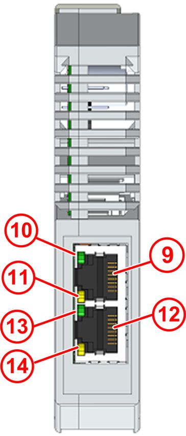
Table of contents                                                                                                                            2/94

                                                       Table of contents
1   Introduction .............................................................................................................................. 4
    1.1      About this document ........................................................................................................         4
             1.1.1    Description of the contents ...............................................................................                 4
             1.1.2    Obligation to read the manual...........................................................................                    4
             1.1.3    List of revisions .................................................................................................         5
             1.1.4    Conventions in this document...........................................................................                     6
             1.1.5    Reference to hardware, firmware, software and drivers ...................................                                   7
    1.2      Contents of the product DVD ......................................................................................... 11
    1.3      Documentation overview................................................................................................ 13
2   Safety ...................................................................................................................................... 16
    2.1      General note .................................................................................................................. 16
    2.2      Intended use .................................................................................................................. 16
    2.3      Personnel qualification ................................................................................................... 16
    2.4      Safety standards ............................................................................................................ 16
    2.5      Safety instructions to avoid personal injury.................................................................... 17
             2.5.1    Danger of unsafe system operation ................................................................ 17
    2.6      Safety instructions to avoid property damage ................................................................                      17
             2.6.1    Device destruction by exceeding allowed supply voltage ...............................                                    17
             2.6.2    Danger of unsafe system operation ................................................................                        17
             2.6.3    Device destruction due to overheating............................................................                         17
             2.6.4    Exceeding the maximum number of permitted write and delete accesses .....                                                 18
    2.7      Labeling of safety messages.......................................................................................... 18
3   Description ............................................................................................................................. 20
    3.1      Functionality ................................................................................................................... 20
    3.2      Protocol conversions...................................................................................................... 22
    3.3      Interfaces ....................................................................................................................... 24
4   Requirements ......................................................................................................................... 25
5   Device drawings and connectors......................................................................................... 26
    5.1      Dimensioned drawings................................................................................................... 26
    5.2      Positions of the interfaces and LEDs ............................................................................. 27
    5.3      Device label.................................................................................................................... 28
    5.4      Protocol logo and LED label sticker ............................................................................... 29
    5.5      Power supply connector................................................................................................. 30
    5.6      Ethernet connectors ....................................................................................................... 31
    5.7      USB interface (Mini-B USB) ........................................................................................... 31
    5.8      Galvanic isolation ........................................................................................................... 32
6   Mounting of device ............................................................................................................... 33
    6.1      Safety messages............................................................................................................ 33
    6.2      Mounting device onto Top Hat Rail ................................................................................ 34
    6.3      Removing device from Top Hat Rail .............................................................................. 35
7   Commissioning ...................................................................................................................... 36

netTAP NT 151-RE-RE | Real-Time Ethernet gateway                                                                                © Hilscher 2021
DOC150802UM06EN | Revision 6 | English | 2021-03 | Released | Public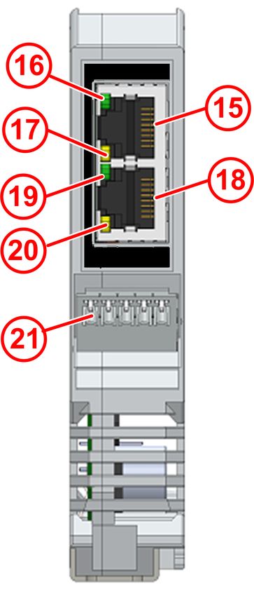
Table of contents                                                                                                                           3/94

8     Firmware recovery ................................................................................................................. 38
      8.1      Overview ........................................................................................................................ 38
      8.2      Using an SD memory card to reset the netTAP to its “factory settings”......................... 39
      8.3      Using USB to recover firmware...................................................................................... 41
9     Using SD memory card to copy configuration data into spare netTAP devices ............. 49
      9.1      Overview ........................................................................................................................ 49
      9.2      Prerequisites .................................................................................................................. 49
      9.3      Step-by-step instructions................................................................................................ 50
10 LEDs........................................................................................................................................ 57
      10.1 Overview ........................................................................................................................ 57
      10.2 SYS LED ........................................................................................................................ 57
      10.3 APL LED ........................................................................................................................ 58
      10.4 LEDs of the Real-Time Ethernet systems ......................................................................                       59
           10.4.1 LEDs PROFINET IO Controller ......................................................................                           59
           10.4.2 LEDs PROFINET IO Device ...........................................................................                          60
           10.4.3 LEDs EtherCAT Master ..................................................................................                      61
           10.4.4 LEDs EtherCAT Slave ....................................................................................                     63
           10.4.5 LEDs EtherNet/IP Scanner .............................................................................                       64
           10.4.6 LEDs EtherNet/IP Adapter ..............................................................................                      66
           10.4.7 LEDs Sercos Master .......................................................................................                   68
           10.4.8 LED Sercos Slave ..........................................................................................                  70
           10.4.9 LEDs POWERLINK Controlled Node..............................................................                                 72
           10.4.10 LEDs OpenModbus/TCP (Client and Server) .................................................                                   73
11 Troubleshooting..................................................................................................................... 74
12 Technical data ........................................................................................................................ 75
      12.1 Technical data netTAP NT 151-RE-RE.......................................................................... 75
      12.2 Technical data of the protocols ......................................................................................              77
           12.2.1 PROFINET IO Controller ................................................................................                      77
           12.2.2 PROFINET IO Device .....................................................................................                     78
           12.2.3 EtherNet/IP Scanner .......................................................................................                  80
           12.2.4 EtherNet/IP Adapter........................................................................................                  81
           12.2.5 EtherCAT Master ............................................................................................                 81
           12.2.6 EtherCAT Slave ..............................................................................................                82
           12.2.7 Sercos Master.................................................................................................               82
           12.2.8 Sercos Slave...................................................................................................              83
           12.2.9 POWERLINK Controlled Node .......................................................................                            83
           12.2.10 Open Modbus/TCP .........................................................................................                   84
13 Decommissioning/Disposal .................................................................................................. 85
      13.1 Putting the device out of operation................................................................................. 85
      13.2 Disposal of waste electronic equipment......................................................................... 85
14 Appendix................................................................................................................................. 86
      14.1 Legal notes..................................................................................................................... 86
      14.2 Registered trademarks................................................................................................... 90
      Contacts.................................................................................................................................. 94

netTAP NT 151-RE-RE | Real-Time Ethernet gateway                                                                               © Hilscher 2021
DOC150802UM06EN | Revision 6 | English | 2021-03 | Released | Public
Introduction                                                                                      4/94

1     Introduction

1.1      About this document

1.1.1        Description of the contents
                          This user manual describes hardware, technical data, installation and
                          commissioning of the Hilscher netTAP gateway device NT 151-RE-RE for
                          Real-Time Ethernet networks.
                          This document also features step-by-step instructions on how to reset the
                          netTAP device to its “factory settings” (a.k.a. “firmware recovery”) and how
                          to use an SD memory card to copy configuration data from one device to
                          another (a.k.a. “cloning” of a spare device).
                          Technical data of the supported Real-Time Ethernet protocols can also be
                          found in this document.
                          The configuration of the NT 151-RE-RE device is not subject of this
                          document. Configuration and firmware download are described in the
                          operating instruction manual Configuration of Gateway and Proxy Devices,
                          DOC081201OIxxEN.
                          Instructions on how to install the necessary configuration software can be
                          found in the user manual Software Installation, DOC100315UMxxEN.
                          Please note also that for the netTAP NT 151-CCIES-RE (gateway for CC-
                          Link IE Field Slave to PROFINET IO Device conversion), there is a
                          separate user manual: netTAP NT 151-CCIES-RE – CC-Link IE Field Slave
                          to PROFINET IO-Device gateway, DOC180403UMxxEN.

1.1.2        Obligation to read the manual

                                   Important:
                                   Ø To avoid personal injury or property damage to your system or
                                      to your device, you must read and understand all instructions in
                                      this manual and in the documents accompanying your device
                                      before installing and operating your device.
                                   Ø First read the Safety Instructions in the chapter
                                      Safety [} page 16].
                                   Ø Observe all Safety Messages in this manual.
                                   Ø Keep the product DVD providing the product manuals.

netTAP NT 151-RE-RE | Real-Time Ethernet gateway                                         © Hilscher 2021
DOC150802UM06EN | Revision 6 | English | 2021-03 | Released | Public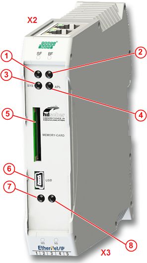
Introduction                                                                                                        5/94

1.1.3        List of revisions
                           Index     Date              Revision
                           2         2017-07-06        Firmware for OpenModbus/TCP and POWERLINK Controlled
                                                       Node in section Hardware and firmware [} page 7] added.
                                                       POWERLINK Controlled Node in section Device description
                                                       files [} page 9] added.
                                                       Section Exceeding the maximum number of permitted write and
                                                       delete accesses [} page 18] added.
                                                       OpenModbus/TCP and POWERLINK Controlled Node in section
                                                       Protocol conversions [} page 22] added.
                                                       LED descriptions for POWERLINK Controlled Node and
                                                       OpenModbus/TCP in section LEDs of the Real-Time Ethernet
                                                       systems [} page 59] added.
                                                       POWERLINK Controlled Node and OpenModbus/TCP in section
                                                       Technical data of the protocols [} page 77] added.
                           3         2017-08-23        Hardware revision 2
                                                       Depiction of MAC addresses in section Device label [} page 28]
                                                       revised.
                                                       LED descriptions in section LEDs EtherCAT Master [} page 61]
                                                       updated according to stack version ≥ V4.
                           4         2018-04-16        Section Contents of the product DVD [} page 11] updated.
                                                       Depiction of bottom side of device in section Positions of the
                                                       interfaces and LEDs [} page 27] revised.
                                                       Section Device label [} page 28] revised.
                                                       Section LEDs EtherNet/IP Scanner [} page 64] updated.
                                                       Section LEDs EtherNet/IP Adapter [} page 66] updated.
                           5         2018-04-26        Note on incompatibility of the GSDML file when using the Auto
                                                       Mapping function during signal configuration of PROFINET IO-
                                                       Device in SYCON.net added in section Device description
                                                       files [} page 9].
                           6         2021-03-12        Firmware version 1.4
                                                       Protocol conversions added:
                                                       · POWERLINK Controlled Node / POWERLINK Controlled
                                                         Node
                                                       · Open Modbus/TCP / PROFINET IO-Controller
                                                       · Open Modbus/TCP / EtherCAT Master
                                                       · Open Modbus/TCP / EtherNet/IP Scanner
                                                       · Open Modbus/TCP / Sercos Master
                                                       · Open Modbus/TCP / Open Modbus/TCP
                                                       Subsection in section Reference to hardware, firmware, software
                                                       and drivers [} page 7] updated.
                                                       Section Contents of the product DVD [} page 11] updated.
                                                       Overview table in section Protocol conversions [} page 22]
                                                       expanded.
                          Table 1: List of revisions

netTAP NT 151-RE-RE | Real-Time Ethernet gateway                                                         © Hilscher 2021
DOC150802UM06EN | Revision 6 | English | 2021-03 | Released | Public
Introduction                                                                                     6/94

1.1.4        Conventions in this document
                          Notes, operation instructions and results of operation steps are marked as
                          follows:

                          Notes

                                   Important:

                                   Note:

                          Operation instructions
                          1.
                          Ø
                          Ø
                          2.
                          Ø
                          Ø

                          Results

                          For a description of the labeling of Safety Messages, see section Labeling
                          of safety messages [} page 18].

netTAP NT 151-RE-RE | Real-Time Ethernet gateway                                        © Hilscher 2021
DOC150802UM06EN | Revision 6 | English | 2021-03 | Released | Public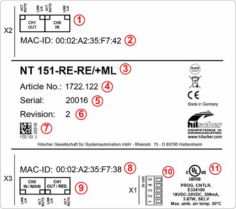
Introduction                                                                                               7/94

1.1.5        Reference to hardware, firmware, software and drivers

1.1.5.1         Hardware and firmware
                           This document relates to the following versions of hardware and firmware
                           of the netTAP NT 151-RE-RE:
Hardware Protocol of primary       Protocol of secondary      Article no.        Firmware file    Firmware
revision network (X2)              network (X3)                                                   version
                                                                                                  (starting from
                                                                                                  this version
                                                                                                  and higher)
2           PROFINET IO-Device     PROFINET IO-Device         1722.122/PNS/PNS   T120D0D0.NXF 1.x
                                   PROFINET IO-Controller     1722.122/PNS/PNM T120D0C0.NXF 1.x
                                   EtherCAT Master            1722.122/PNS/ECM T120D0E0.NXF 1.x
                                   Sercos Master              1722.122/PNS/S3M   T120D0I0.NXF     1.x
                                   EtherNet/IP Scanner        1722.122/PNS/EIM   T120D0G0.NXF 1.x
                                   Open Modbus/TCP            1722.122/PNS/OMB T120D0L0.NXF 1.x
            EtherCAT Slave         PROFINET IO-Device         1722.122/ECS/PNS   T120F0D0.NXF 1.x
                                   PROFINET IO-Controller     1722.122/ECS/PNM T120F0C0.NXF 1.x
                                   EtherCAT Slave             1722.122/ECS/ECS   T120F0F0.NXF 1.x
                                   EtherCAT Master            1722.122/ECS/ECM T120F0E0.NXF 1.x
                                   Sercos Master              1722.122/ECS/S3M   T120F0I0.NXF     1.x
                                   EtherNet/IP Adapter        1722.122/ECS/EIS   T120F0H0.NXF 1.x
                                   EtherNet/IP Scanner        1722.122/ECS/EIM   T120F0G0.NXF 1.x
                                   Open Modbus/TCP            1722.122/ECS/OMB T120F0L0.NXF 1.x
            Sercos Slave           PROFINET IO-Device         1722.122/S3S/PNS   T120J0D0.NXF 1.x
                                   PROFINET IO-Controller     1722.122/S3S/PNM   T120J0C0.NXF 1.x
                                   EtherCAT Slave             1722.122/S3S/ECS   T120J0F0.NXF 1.x
                                   EtherCAT Master            1722.122/S3S/ECM   T120J0E0.NXF 1.x
                                   Sercos Slave               1722.122/S3S/S3S   T120J0J0.NXF     1.x
                                   Sercos Master              1722.122/S3S/S3M   T120J0I0.NXF     1.x
                                   EtherNet/IP Adapter        1722.122/S3S/EIS   T120J0H0.NXF 1.x
                                   EtherNet/IP Scanner        1722.122/S3S/EIM   T120J0G0.NXF 1.x
                                   Open Modbus/TCP            1722.122/S3S/OMB   T120J0L0.NXF     1.x
            EtherNet/IP Adapter    PROFINET IO-Device         1722.122/EIS/PNS   T120H0D0.NXF 1.x
                                   PROFINET IO-Controller     1722.122/EIS/PNM   T120H0C0.NXF 1.x
                                   EtherCAT Master            1722.122/EIS/ECM   T120H0E0.NXF 1.x
                                   Sercos Master              1722.122/EIS/S3M   T120H0I0.NXF     1.x
                                   EtherNet/IP Adapter        1722.122/EIS/EIS   T120H0H0.NXF 1.x
                                   EtherNet/IP Scanner        1722.122/EIS/EIM   T120H0G0.NXF 1.x
                                   Open Modbus/TCP            1722.122/EIS/OMB   T120H0L0.NXF 1.x
            POWERLINK              PROFINET IO-Device         1722.122/PLS/PNS   T120K0D0.NXF 1.x
            Controlled Node        PROFINET IO-Controller     1722.122/PLS/PNM   T120K0C0.NXF 1.x
                                   EtherCAT Slave             1722.122/PLS/ECS   T120K0F0.NXF 1.x
                                   EtherCAT Master            1722.122/PLS/ECM   T120K0E0.NXF 1.x
                                   EtherNet/IP Adapter        1722.122/PLS/EIS   T120K0H0.NXF 1.x
                                   EtherNet/IP Scanner        1722.122/PLS/EIM   T120K0G0.NXF 1.x
                                   Sercos Slave               1722.122/PLS/S3S   T120K0J0.NXF 1.x
                                   Sercos Master              1722.122/PLS/S3M   T120K0I0.NXF     1.x
                                   Open Modbus/TCP            1722.122/PLS/OMB   T120K0L0.NXF 1.x
                                   POWERLINK Controlled       1722.122/PLS/PLS   T120K0K0.NXF 1.4
                                   Node

netTAP NT 151-RE-RE | Real-Time Ethernet gateway                                                 © Hilscher 2021
DOC150802UM06EN | Revision 6 | English | 2021-03 | Released | Public
Introduction                                                                                               8/94

Hardware Protocol of primary       Protocol of secondary      Article no.        Firmware file    Firmware
revision network (X2)              network (X3)                                                   version
                                                                                                  (starting from
                                                                                                  this version
                                                                                                  and higher)
2           Open Modbus/TCP        PROFINET IO-Controller     1722.122/OMB/PNM T120L0C0.NXF 1.4
                                   EtherCAT Master            1722.122/OMB/ECM T120L0E0.NXF 1.4
                                   EtherNet/IP Scanner        1722.122/OMB/EIM   T120L0G0.NXF 1.4
                                   Sercos Master              1722.122/OMB/S3M T120L0I0.NXF       1.4
                                   Open Modbus/TCP            1722.122/OMB/OMB T120L0L0.NXF 1.4
                          Table 2: Reference to firmware

netTAP NT 151-RE-RE | Real-Time Ethernet gateway                                                 © Hilscher 2021
DOC150802UM06EN | Revision 6 | English | 2021-03 | Released | Public
Introduction                                                                                                   9/94

1.1.5.2           Software
                             This document relates to the following software versions:
Software              Version        File name                        Path on Gateway Solutions DVD
SYCON.net             1.500.x.x      SYCONnet netX setup.exe Software_&_Tools\
                                                             Configuration_Software\
                                                             SYCON.net\
                             Table 3: Reference to software

1.1.5.3           Device description files
                             This document relates to the following device description files:
If used as         Devices                 File name                                    Path on Gateway Solutions
                                                                                        DVD
PROFINET IO        1722.122/PNS/PNS        GSDML-V2.31-HILSCHER-NT 151-RE-             Firmware, EDS,
Device             1722.122/PNS/PNM        RE PNS-20151021.xml                         Examples, Webpages
                   1722.122/PNS/ECM
                                           Note: You cannot use this GSDML file if you \Firmware & EDS\
                   1722.122/PNS/S3M
                                           use the Auto Mapping function for mapping netTAP 151\
                   1722.122/PNS/EIM                                                    DeviceDescription\PNS
                                           signals when configuring your netTAP in
                   1722.122/ECS/PNS
                                           SYCON.net. In this case you must generate
                   1722.122/S3S/PNS
                                           a new file by using the Export GSDML
                   1722.122/EIS/PNS
                                           function.
EtherCAT Slave     1722.122/ECS/PNS        Hilscher NT 151XX ECS V4.2.X.xml Firmware, EDS,
                   1722.122/ECS/PNM                                         Examples, Webpages
                   1722.122/ECS/ECS                                         \Firmware & EDS\
                   1722.122/ECS/ECM                                         netTAP 151\
                   1722.122/ECS/S3M                                         DeviceDescription\ECS
                   1722.122/ECS/EIS
                   1722.122/ECS/EIM
                   1722.122/S3S/ECS
                   1722.122/EIS/ECS
Sercos Slave       1722.122/S3S/PNS        SDDML#v3.0#Hilscher#NT_151-                  Firmware, EDS,
                   1722.122/S3S/PNM        RE_RE_S3S_FIXCFG#2017-07-25.xml              Examples, Webpages
                   1722.122/S3S/ECS        for 2 byte input and 2 byte output data.     \Firmware & EDS\
                   1722.122/S3S/ECM                                                     netTAP 151\
                                           Note: Create with SYCON.net a device
                   1722.122/S3S/S3S                                                     DeviceDescription\S3S
                                           description file matching the used
                   1722.122/S3S/S3M
                                           configuration by using the Export SDDML
                   1722.122/S3S/EIS
                                           function.
                   1722.122/S3S/EIM
EtherNet/IP        1722.122/EIS/PNS        HILSCHER NT 151-RE-RE EIS                    Firmware, EDS,
Adapter            1722.122/EIS/PNM        V1.1.EDS                                     Examples, Webpages
                   1722.122/EIS/ECM                                                     \Firmware & EDS\
                   1722.122/EIS/S3M                                                     netTAP 151\
                   1722.122/EIS/EIS                                                     DeviceDescription\EIS
                   1722.122/EIS/EIM
POWERLINK          1722.122/PLS/PNS        00000044_NT151PLS-64O_64I.xdd                Firmware, EDS,
Controlled Node    1722.122/PLS/PNM        for 64 byte input and 64 byte output data.   Examples, Webpages
                   1722.122/PLS/ECS                                                     \Firmware & EDS\
                                           00000044_NT151PLS-512O_512I.xdd
                   1722.122/PLS/ECM
                                           for 512 byte input and 512 byte output data. netTAP 151\
                   1722.122/PLS/S3S                                                     DeviceDescription\PLS
                   1722.122/PLS/S3M
                   1722.122/PLS/EIS
                   1722.122/PLS/EIM
                   1722.122/PLS/PLS
                   1722.122/PLS/OMB
                             Table 4: Reference on device description files

netTAP NT 151-RE-RE | Real-Time Ethernet gateway                                                      © Hilscher 2021
DOC150802UM06EN | Revision 6 | English | 2021-03 | Released | Public
Introduction 10/94
1.1.5.4 Drivers
This document relates to the following driver:
Driver File name Path on Gateway Solutions DVD
Installation program for setup.exe Driver & Toolkit\
Windows USB drivers Device Driver\USB Driver
Table 5: Reference to drivers
netTAP NT 151-RE-RE | Real-Time Ethernet gateway © Hilscher 2021
DOC150802UM06EN | Revision 6 | English | 2021-03 | Released | PublicIntroduction 11/94
1.2 Contents of the product DVD
The Gateway Solutions product DVD contains:
· SYCON.net configuration and diagnostic program for Windows
· USB drivers for Windows
· PDF documentation
· Firmware
· Device description files
· Tools
Directory of the DVD:
Folder Contents
Documentation
1. Software Operating instruction manuals for device configuration (PDF)
Ethernet Device Setup Utility
SYCON.net Configuration Software
2. Hardware User manuals of the gateway devices (PDF)
netLINK PROXY, Model NL 51N-DPL
netTAP 50, Model NT 50-xx-yy
netTAP 100, Model NT 100-xx-yy
netTAP 151, Model NT 151-CCIES-RE
netTAP 151, Model NT 151-RE-RE
3. For Programmers Documentation for developers (PDF)
Error Codes Compilation
IO Data Flow Control of 3964R protocol
IO Data Flow Control of ASCII protocol
Modbus RTU Specification
Modbus TCP Specification
netSCRIPT Scripting Language
4. PLC Application Notes
CCLINK IE - PROFINET coupler
specification
Controllogix PLCs - EthernetIP
Integration
SIMATIC PLCs - Consistent Data
PROFIBUS,PROFINET
SIMATIC PLCs - Migration from
PROFIBUS to PROFINET
Simple TCPIP connectivity through
Modbus TCP
5. Installation Instructions Wiring and software installation instructions for standard users (PDF)
netTAP NT 151-RE-RE | Real-Time Ethernet gateway © Hilscher 2021
DOC150802UM06EN | Revision 6 | English | 2021-03 | Released | PublicIntroduction 12/94
Folder Contents
Firmware, EDS, Examples, Webpages Loadable firmware files and device description files
Firmware & EDS
netLINK PROXY
netTAP 50
netTAP 100
netTAP 151 Loadable firmware files for NT 151
DeviceDescription Device description files for NT 151
ECS EtherCAT Slave
EIS EtherNet/IP Adapter
PLS POWERLINK Controlled Node
PNS PROFINET IO-Device
S3S Sercos Slave
Driver & Toolkit
Device Driver USB Driver
Driver Toolkit Driver Toolkit
Supplements & Examples
Device Factory Reset Tools for resetting the devices to their “factory settings”
netTAP 100 Factory Settings
netTAP 151 CCLINK IE Factory Settings
netTAP 151 Factory Settings
NL 51N-DPL Factory Settings
Modbus RTU,TCP Technical Resources
Source Code from www.freemodbus.org
(Freeware)
Test Tools from www.modbustools.com
(Shareware)
netSCRIPT Source Codes
RSLogix5000 Projects
Siemens STEP7 Projects Example project acyclic communication PROFINET IO-Device to
Ethernet IP Scanner
SYCON.net Projects SYCON.net example projects
UnityProXL Projects
Table 6: Directory of Gateway Solutions DVD
netTAP NT 151-RE-RE | Real-Time Ethernet gateway © Hilscher 2021
DOC150802UM06EN | Revision 6 | English | 2021-03 | Released | PublicIntroduction 13/94
1.3 Documentation overview
This section lists documents that are relevant to the user of the netTAP NT
151-RE-RE device.
Basic documents
Title Contents Document ID Path on the Gateway Solutions DVD
User Manual Installation, DOC150802UMxxEN Documentation\english\2.Hardware
netTAP NT 151-RE- commissioning and \netTAP 151, Model NT 151-RE-RE\netTAP
RE – Real-Time hardware description NT 151-RE-RE UM xx EN.pdf
Ethernet Gateway of the NT 151 device
(this document) and other technical
data
Operating Configuring, testing, DOC081201OIxxEN Documentation\english\1.Software\SYCON.net
Instruction Manual diagnosing and Configuration Software\Configuration of Gateway
Configuration of updating firmware of and Proxy Devices OI xx EN.pdf
Gateway and Proxy the NT 151 device
Devices,
User Manual Instructions for DOC100315UMxxEN Documentation\english\5.Installation Instructions\
Software Installation installing the Software Installation - Gateway Solutions UM xx
Gateway Solutions configuration EN.pdf
software
Table 7: Basic documentation for NT 151-RE-RE
NT 151-RE-RE as PROFINET IO Controller
You also need the following documents if you are using the device as
PROFINET IO Controller:
Title Contents Document ID Path on the Gateway Solutions DVD
Operating Description of the DOC060302OIxxEN Documentation\english\1.Software\SYCON.net
Instruction Manual device type manager Configuration Software\Master Configuration
DTM for Hilscher- for PROFINET IO \PROFINET IO Controller\PROFINET IO Controller
PROFINET IO- Controller devices DTM OI xx EN.pdf
Controller Devices
Operating Description of the DOC060305OIxxEN Documentation\english\1.Software\SYCON.net
Instruction Manual device type manager Configuration Software\Master Configuration
Generic DTM for for generic \PROFINET IO Controller \IO Device Configuration
PROFINET IO PROFINET IO \PROFINET IO Generic Device DTM OI xx EN.pdf
Devices devices
Table 8: Additional documentation for NT 151-RE-RE as PROFINET IO Controller
netTAP NT 151-RE-RE | Real-Time Ethernet gateway © Hilscher 2021
DOC150802UM06EN | Revision 6 | English | 2021-03 | Released | PublicIntroduction 14/94
NT 151-RE-RE as PROFINET IO Device
You also need the following document if you are using the device as
PROFINET IO Device:
Title Contents Document ID Path on the Gateway Solutions DVD
Operating Description of the DOC060305OIxxEN Documentation\english\1.Software\SYCON.net
Instruction Manual device type manager Configuration Software\Master Configuration
Generic DTM for for generic \PROFINET IO Controller \IO Device Configuration
PROFINET IO PROFINET IO \PROFINET IO Generic Device DTM OI xx EN.pdf
Devices devices
Table 9: Additional documentation for NT 151-RE-RE as PROFINET IO Device
NT 151-RE-RE as EtherCAT Master
You also need the following documents if you are using the device as
EtherCAT Master:
Title Contents Document ID Path on the Gateway Solutions DVD
Operating Description of the DOC080404OIxxEN Documentation\english\1.Software\SYCON.net
Instruction Manual device type manager Configuration Software\Master Configuration
DTM for Hilscher for EtherCAT Master \EtherCAT Master\EtherCAT Master DTM OI xx
EtherCAT Master devices EN.pdf
Device
Operating Description of the DOC071202OIxxEN Documentation\english\1.Software\SYCON.net
Instruction Manual device type manager Configuration Software\Master Configuration
Generic Slave DTM for generic EtherCAT \EtherCAT Master\Slave Configuration\EtherCAT
for EtherCAT Slave slave devices Generic Slave DTM OI xx EN.pdf
Devices
User Manual Wiring instructions DOC121104UMxxEN Documentation\english\5.Installation Instructions\
Wiring Instructions for EtherCAT Wiring Instructions UM xx EN.pdf
EtherCAT networks
Table 10: Additional documentation for NT 151-RE-RE as EtherCAT Master
NT 151-RE-RE as EtherCAT Slave
You also need the following document if you are using the device as
EtherCAT Slave:
Title Contents Document ID Path on the Gateway Solutions DVD
User Manual Wiring instructions DOC121104UMxxEN Documentation\english\5.Installation Instructions\
Wiring Instructions for EtherCAT Wiring Instructions UM xx EN.pdf
EtherCAT networks
Table 11: Additional documentation for NT 151-RE-RE as EtherCAT Slave
netTAP NT 151-RE-RE | Real-Time Ethernet gateway © Hilscher 2021
DOC150802UM06EN | Revision 6 | English | 2021-03 | Released | PublicIntroduction 15/94
NT 151-RE-RE as EtherNet/IP Scanner
You also need the following documents if you are using the device as
EtherNet/IP Scanner:
Title Contents Document ID Path on the Gateway Solutions DVD
Operating Description of the DOC061201OIxxEN Documentation\english\1.Software\SYCON.net
Instruction Manual device type manager Configuration Software\Master Configuration
DTM for EtherNet/IP for EtherNet/IP \EtherNetIP Scanner\EtherNetIP Scanner DTM OI
Scanner Devices Scanner devices xx EN.pdf
Operating Description of the DOC100221OIxxEN Documentation\english\1.Software\SYCON.net
Instruction Manual generic, modular Configuration Software\Master Configuration
Generic, Modular generic device type \EtherNetIP Scanner\Adapter Configuration
Generic DTM from manager from EDS \EtherNetIP Generic Adapter DTM EDS OI xx
EDS File for non- file for non-modular EN.pdf
modular and EtherNet/IP Adapter
modular EtherNet/IP devices and modular
Adapter Devices EtherNet/IP Adapter
devices
Operating Description of the DOC070203OIxxEN Documentation\english\1.Software\SYCON.net
Instruction Manual generic device type Configuration Software\Master Configuration
Generic DTM for manager for \EtherNetIP Scanner\Adapter Configuration
EtherNet/IP Adapter EtherNet/IP Adapter \EtherNetIP Generic Adapter DTM OI xx EN.pdf
Devices and devices and modular
Modular Generic EtherNet/IP Adapter
DTM for modular devices
EtherNet/IP Adapter
Devices
Table 12: Additional documentation for NT 151-RE-RE as EtherNet/IP Scanner
NT 151-RE-RE as Sercos Master
You also need the following documents if you are using the device as
Sercos Master:
Title Contents Document ID Path on the Gateway Solutions DVD
Operating Description of the DOC090301OIxxEN Documentation\english\1.Software\SYCON.net
Instruction Manual device type manager Configuration Software\Master Configuration\sercos
DTM for Hilscher for sercos master Master\sercos Master DTM OI xx EN.pdf
sercos Master devices
Devices
Operating Description of the DOC090302UMxxEN Documentation\english\1.Software\SYCON.net
Instruction Manual device type manager Configuration Software\Master Configuration\sercos
Generic Slave DTM for generic sercos Master\Slave Configuration\sercos Generic Slave
for sercos Slave slave devices DTM OI xx EN.pdf
Devices
Table 13: Additional documentation for NT 151-RE-RE as Sercos Master
netTAP NT 151-RE-RE | Real-Time Ethernet gateway © Hilscher 2021
DOC150802UM06EN | Revision 6 | English | 2021-03 | Released | PublicSafety 16/94
2 Safety
2.1 General note
The user manual, the accompanying texts and the documentation are
written for the use of the products by educated personnel. When using the
products, all safety instructions and all valid legal regulations have to be
obeyed. Technical knowledge is presumed. The user has to assure that all
legal regulations are obeyed.
2.2 Intended use
The netTAP NT 151-RE-RE device described in this manual is a
communication device connecting two separate Real-Time Ethernet
networks with each other. The device thus serves as a “gateway” between
the two networks.
The netTAP NT 151-RE-RE device is equipped with a compact housing
and is intended for DIN rail mounting according to DIN EN 60715.
2.3 Personnel qualification
The netTAP must be installed, configured and removed only by qualified
personnel. Job-specific technical skills for people professionally working
with electricity must be present concerning the following topics:
· Safety and health at work
· Mounting and connecting of electrical equipment
· Measurement and Analysis of electrical functions and systems
· Evaluation of the safety of electrical systems and equipment
· Installing and Configuring IT systems
2.4 Safety standards
[S1] ANSI Z535.6-2016 American National Standard for Product Safety Information in
Product Manuals, Instructions, and Other Collateral Materials
[S2] DIN EN 62368-1: 2016-05, Audio/video, information and communication technology
equipment - Part 1: Safety requirements (IEC 62368-1: 2014, modified +
Cor.:2015); German version EN 62368-1: 2014 + AC: 2015
[S3] EN 61340-5-1 and EN 61340-5-2 as well as IEC 61340-5-1 and IEC 61340-5-2
netTAP NT 151-RE-RE | Real-Time Ethernet gateway © Hilscher 2021
DOC150802UM06EN | Revision 6 | English | 2021-03 | Released | PublicSafety 17/94
2.5 Safety instructions to avoid personal injury
To ensure your own personal safety and to avoid personal injury, you must
read, understand and follow the safety instructions and all safety messages
in this manual about danger that might cause personal injury, before you
install and operate your netTAP device.
2.5.1 Danger of unsafe system operation
To prevent personal injury, make sure that the removal of the netTAP
device from your plant during operation will not affect the safe operation of
the plant.
2.6 Safety instructions to avoid property damage
To avoid property damage to your system or to the netTAP device, you
must read, understand and follow the safety instructions and all safety
messages in this manual about danger that might cause property damage,
before you install and operate your device.
2.6.1 Device destruction by exceeding allowed supply voltage
Observe the following notes concerning the supply voltage:
· The netTAP device may only be operated with the specified supply
voltage. Make sure that the limits of the allowed range for the supply
voltage are not exceeded.
· A supply voltage above the upper limit can cause severe damage to the
device!
· A supply voltage below the lower limit can cause malfunction of the
device.
The allowed range for the supply voltage of the netTAP device is specified
in section Technical data netTAP NT 151-RE-RE [} page 75].
2.6.2 Danger of unsafe system operation
To prevent property damage, make sure that the removal of the netTAP
device from your plant during operation will not affect safe operation of the
plant.
2.6.3 Device destruction due to overheating
The air ventilation slots of the netTAP device must not be covered by any
objects, otherwise the device might overheat!
Maximum environmental temperature is +60 °C.
If the environmental temperature exceeds +50 °C, you must allow for a
minimum of 17.5 mm distance between the netTAP and neighboring
devices.
netTAP NT 151-RE-RE | Real-Time Ethernet gateway © Hilscher 2021
DOC150802UM06EN | Revision 6 | English | 2021-03 | Released | PublicSafety 18/94
2.6.4 Exceeding the maximum number of permitted write and delete
accesses
This device uses a serial flash chip to store remanent data such as
firmware storage, configuration storage, etc. This device allows a maximum
of 100,000 write/delete accesses that are sufficient for standard operation
of the device. However, writing/deleting the chip excessively (e.g. changing
the configuration or changing the name of station) leads to the maximum
number of permitted write/delete accesses being exceeded and to device
damage. For example, if the configuration is changed once an hour, the
maximum number is reached after 11.5 years. If the configuration is
changed even more frequently, for example once a minute, the maximum
number is reached after approx. 69 days.
Avoid exceeding the maximum permitted write/delete accesses by writing
too often.
2.7 Labeling of safety messages
In this document the safety instructions and property damage messages
are designed according both to the internationally used safety conventions
as well as to the ANSI Z535 standard.
· The Section Safety Messages at the beginning of a chapter are
pinpointed particularly and highlighted by a signal word according to the
degree of endangerment. The kind of danger is specified exactly by the
safety message text and optionally by a specific safety sign.
· The Integrated Safety Messages embedded in operating instructions
are highlighted by a signal word according to the degree of
endangerment. In the safety message, the nature of the hazard is
indicated.
Signal words and safety signs in safety messages on personal injury
Signal word Meaning
Indicates a direct hazard with high risk, which will have as consequence
death or grievous bodily harm if it is not avoided.
Indicates a possible hazard with medium risk, which will have as
consequence death or (grievous) bodily harm if it is not avoided.
Indicates a minor hazard with medium risk, which could have as
consequence personal injury if it is not avoided.
Table 14: Signal words in safety messages on personal injury
Safety sign Sort of warning or principle
Warning of lethal electrical shock
Principle: Disconnect the power plug
Table 15: Safety signs in messages on personal injury
netTAP NT 151-RE-RE | Real-Time Ethernet gateway © Hilscher 2021
DOC150802UM06EN | Revision 6 | English | 2021-03 | Released | PublicSafety 19/94
Signal words and safety signs in safety messages on property
damage
Signal word Meaning
Indicates a property damage message
Table 16: Signal words in safety messages on property damage
Safety sign Sort of warning or principle
Warning of property damage by electrostatic discharge
Table 17: Safety signs in safety messages on property damage
netTAP NT 151-RE-RE | Real-Time Ethernet gateway © Hilscher 2021
DOC150802UM06EN | Revision 6 | English | 2021-03 | Released | PublicDescription 20/94
3 Description
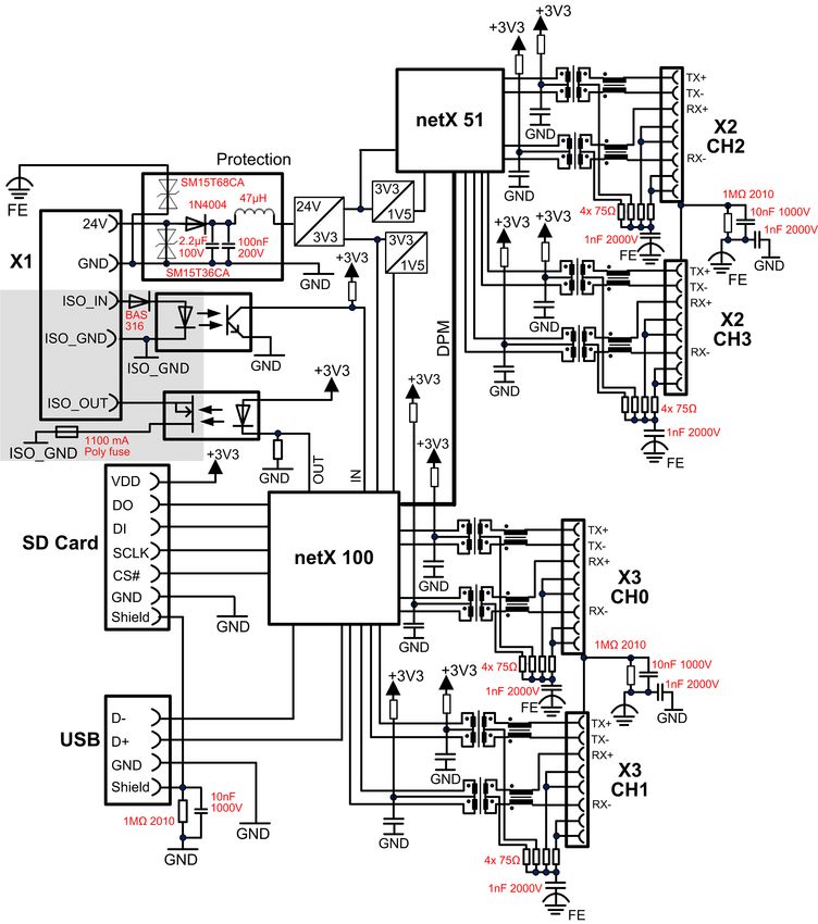
3.1 Functionality
The netTAP NT 151-RE-RE device is a communication gateway connecting
two separate Real-Time Ethernet networks. The two networks can be either
using the same (e. g. PROFINET IO to PROFINET IO) or two different RTE
network systems protocols (e. g. EtherNet/IP to PROFINET IO).
The NT 151-RE-RE always acts as slave device in the primary network
(which is connected at gateway interface X2); in the secondary network
however (which is connected at gateway interface X3), it can act either as
slave or as master device.
For processing the communication, each of the device’s two network
interfaces has its own netX controller: the primary network interface (X2) is
controlled by the netX 51, the secondary network interface (X3) by the
more powerful netX 100.
Figure 1: Data flow netTAP NT 151-RE-RE
netTAP NT 151-RE-RE | Real-Time Ethernet gateway © Hilscher 2021
DOC150802UM06EN | Revision 6 | English | 2021-03 | Released | PublicDescription 21/94
The protocol conversion (e. g. PROFINET IO Device to EtherNet/IP
Scanner) is determined by the firmware installed in the device.
The communication parameters are to be configured by the user himself by
means of the SYCON.net configuration and diagnosis software, which is
included in the scope of delivery.
The netTAP NT 151-RE-RE device is equipped with a compact housing
and is suitable for DIN rail mounting according to DIN EN 60715.
netTAP NT 151-RE-RE | Real-Time Ethernet gateway © Hilscher 2021
DOC150802UM06EN | Revision 6 | English | 2021-03 | Released | PublicDescription 22/94
3.2 Protocol conversions
The protocol conversion of the NT 151-RE-RE is determined by the
firmware installed in the device. By customer’s choice, the device can be
ordered with or without pre-installed firmware. Devices shipped without pre-
installed firmware are only equipped with a “base firmware” which enables
customers to perform a firmware download by using the SYCON.net
configuration software on a PC connected to the device via USB. The
loadable firmware files and SYCON.net are provided on the Gateway
Solutions DVD. Instructions for downloading firmware to the device with
SYCON.net can be found in the operating instruction manual Configuration
of Gateway and Proxy Devices, DOC081201OIxxEN.
netTAPs acting as master in the secondary network also require a master
license in the device. If stated accordingly on ordering, devices intended for
being used as masters (devices with or without preloaded firmware alike)
will be delivered with pre-installed master licenses.
netTAP NT 151-RE-RE | Real-Time Ethernet gateway © Hilscher 2021
DOC150802UM06EN | Revision 6 | English | 2021-03 | Released | PublicDescription 23/94
The following table shows the article numbers and the firmware names
(NXF) of the protocol conversions that are currently available for the
netTAP NT 151-RE-RE device:
Primary network (X2)
PROFINET EtherCAT Sercos Slave EtherNet/IP POWERLINK Open
IO Device Slave Adapter Controlled Modbus/
Node TCP
Secondary network (X3)
PROFINET IO Device 1722.122 1722.122 1722.122 1722.122 1722.122 -
/PNS/PNS /ECS/PNS /S3S/PNS /EIS/PNS /PLS/PNS
T120D0D0 T120F0D0 T120J0D0 T120H0D0 T120K0D0
.NXF .NXF .NXF .NXF .NXF
Controller 1722.122 1722.122 1722.122 1722.122 1722.122 1722.122
/PNS/PNM /ECS/PNM /S3S/PNM /EIS/PNM /PLS/PNM /OMB/PNM
T120D0C0 T120F0C0 T120J0C0 T120H0C0 T120K0C0 T120L0C0
.NXF .NXF .NXF .NXF .NXF .NXF
EtherCAT Slave - 1722.122 1722.122 - 1722.122
/ECS/ECS /S3S/ECS /PLS/ECS
T120F0F0 T120J0F0 T120K0F0
.NXF .NXF .NXF
Master 1722.122 1722.122 1722.122 1722.122 1722.122 1722.122
/PNS/ECM /ECS/ECM /S3S/ECM /EIS/ECM /PLS/ECM /OMB/ECM
T120D0E0 T120F0E0 T120J0E0 T120H0E0 T120K0E0 T120L0E0
.NXF .NXF .NXF .NXF .NXF .NXF
Sercos Slave - - 1722.122 - 1722.122 -
/S3S/S3S /PLS/S3S
T120J0J0 T120K0J0
.NXF .NXF
Master 1722.122 1722.122 1722.122 1722.122 1722.122 1722.122
/PNS/S3M /ECS/S3M /S3S/S3M /EIS/S3M /PLS/S3M /OMB/S3M
T120D0I0 T120F0I0 T120J0I0 T120H0I0 T120K0I0 T120L0I0
.NXF .NXF .NXF .NXF .NXF .NXF
EtherNet/IP Adapter - 1722.122 1722.122 1722.122 1722.122 -
/ECS/EIS /S3S/EIS /EIS/EIS /PLS/EIS
T120F0H0 T120J0H0 T120H0H0 T120K0H0
.NXF .NXF .NXF .NXF
Scanner 1722.122 1722.122 1722.122 1722.122 1722.122 1722.122
/PNS/EIM /ECS/EIM /S3S/EIM /EIS/EIM /PLS/EIM /OMB/EIM
T120D0G0 T120F0G0 T120J0G0 T120H0G0 T120K0G0 T120L0G0
.NXF .NXF .NXF .NXF .NXF .NXF
POWERLINK Controlled - - - - 1722.122 -
Node /PLS/PLS
T120K0K0
.NXF
Open Modbus/ Server 1722.122 1722.122 1722.122 1722.122 1722.122 1722.122
TCP Client /PNS/OMB /ECS/OMB /S3S/OMB /EIS/OMB /PLS/OMB /OMB/OMB
T120D0L0 T120F0L0 T120J0L0 T120H0L0 T120K0L0 T120L0L0
.NXF .NXF .NXF .NXF .NXF .NXF
Table 18: Available protocol conversions with article numbers and firmware names
Note:
For the conversion of CC-Link IE Field Slave to PROFINET IO
Device, Hilscher offers a separate netTAP with special hardware,
i.e. the NT 151-CCIES-RE. For more information about this device,
see user manual netTAP NT 151-CCIES-RE – CC-Link IE Field
Slave to PROFINET IO-Device gateway, DOC180403UMxxEN.
netTAP NT 151-RE-RE | Real-Time Ethernet gateway © Hilscher 2021
DOC150802UM06EN | Revision 6 | English | 2021-03 | Released | PublicDescription 24/94
3.3 Interfaces
The Ethernet interface for the primary network (X2), consisting of two RJ45
jacks, is located on the upper side of the NT 151-RE-RE device, the
Ethernet interface for the secondary network (X3), also consisting of two
RJ45 jacks, is located on the bottom side of the device. The configuration
interfaces (Mini USB socket and SD memory card slot) are easily
accessible at the front of the device.
netTAP NT 151-RE-RE | Real-Time Ethernet gateway © Hilscher 2021
DOC150802UM06EN | Revision 6 | English | 2021-03 | Released | PublicRequirements 25/94
4 Requirements
Technical requirements
· The netTAP NT 151-RE-RE device is to be mounted on a DIN rail
according to DIN EN 60715.
· A suitable external power supply is required.
· The voltage to be applied must be in the allowed range 24 V ± 6 V DC.
· The power supply must be able to deliver at least a current of 190 mA at
24 V.
Device Destruction by Exceeding Allowed Supply Voltage!
The voltage must not exceed 30 V, otherwise the device may be destroyed
or damaged.
In order to avoid damage caused by overheating or freezing, it is necessary
that the temperature of the device does not exceed the limits of the allowed
temperature range. For the allowed temperature, see section Technical
data netTAP NT 151-RE-RE [} page 75].
Requirements for using the SYCON.net configuration software
For installing and operating the SYCON.net configuration software on your
PC, you need the following:
· PC with 1 GHz processor or higher
· Windows® 7 (32 bit) SP1, Windows® 7 (64 bit) SP1, Windows® 8 (32 bit)
or Windows® 8 (64 bit), Windows® 10 (32 bit) or Windows® 10 (64 bit)
· Administrator privilege required for installation
· Internet Explorer 5.5 or higher
· Free disk space: min. 400 MByte
· DVD ROM drive
· RAM: min. 512 MByte, recommended 1024 MByte
· Graphic resolution: min. 1024 x 768 pixel
· Keyboard and Mouse
· USB interface
netTAP NT 151-RE-RE | Real-Time Ethernet gateway © Hilscher 2021
DOC150802UM06EN | Revision 6 | English | 2021-03 | Released | PublicDevice drawings and connectors 26/94
5 Device drawings and connectors
5.1 Dimensioned drawings
Outer dimensions of the netTAP NT 151:
Figure 2: Outer dimensions of NT 151
Dimensions of the power supply plug:
Figure 3: Dimensions of Mini COMBICON power supply plug
Important:
When planning the installation of the netTAP device, reserve
sufficient room above and below the device to allow for convenient
plugging or unplugging of the network and power supply cables.
netTAP NT 151-RE-RE | Real-Time Ethernet gateway © Hilscher 2021
DOC150802UM06EN | Revision 6 | English | 2021-03 | Released | PublicDevice drawings and connectors 27/94
5.2 Positions of the interfaces and LEDs
(1) Protocol specific LED (COM2) at X2
(2) Protocol specific LED (COM3) at X2
(3) SYS LED (system status)
(4) APL LED (application status)
(5) Slot for SD memory card
(part number of card 1719.003)
(6) Mini-USB interface
(7) Protocol specific LED (COM0) at X3
(8) Protocol specific LED (COM1) at X3
(9) Real-Time Ethernet interface channel 2
(X2, RJ45 socket)
(10) LINK LED for Real-Time Ethernet interface channel 2
(11) ACT LED for Real-Time Ethernet interface channel 2
(activity)
(12) Real-Time Ethernet interface channel 3
(X2, RJ45 socket)
(13) LINK LED for Real-Time Ethernet interface channel 3
(14) ACT LED for Real-Time Ethernet interface channel 3
(activity)
(15) Real-Time Ethernet interface channel 0
(X3, RJ45 socket)
(16) LINK LED for Real-Time Ethernet interface channel 0
(17) ACT LED for Real-Time Ethernet interface channel 0
(activity)
(18) Real-Time Ethernet interface channel 1
(X3, RJ45 socket)
(19) LINK LED for Real-Time Ethernet interface channel 1
(20) ACT LED for Real-Time Ethernet interface channel 1
(activity)
NT 151-RE-RE front view (21) Connector for supply voltage (X1)
Top view (X2) Bottom view (X3)
Table 19: LEDs and interfaces NT 151-RE-RE
netTAP NT 151-RE-RE | Real-Time Ethernet gateway © Hilscher 2021
DOC150802UM06EN | Revision 6 | English | 2021-03 | Released | PublicDevice drawings and connectors 28/94
5.3 Device label
Each netTAP NT 151-RE-RE carries a device type label providing the
following information:
(1) Labelling of channels and LEDs of the
connectors of the primary network at X2
(2) MAC address at X2 *
(3) Device type ID
In case the device has a master license, it is
followed by +ML
(4) Article number
(5) Serial number of device
(6) Hardware revision number
(7) Matrix label
(8) MAC address at X3 *
(9) Labelling of channels and LEDs of the
connectors of the secondary network at X3
(10) Labelling of supply voltage connector (X1)
(11) UL label
* three additional MAC addresses are reserved
for each network interface
If your netTAP has been delivered with pre-loaded firmware, you will also
find on the device type label an indication of the protocol loaded at X2
respectively X3.
Abbreviation Protocol
PNM PROFINET IO Controller
PNS PROFINET IO Device
ECM EtherCAT Master
ECS EtherCAT Slave
S3M Sercos Master
S3S Sercos Slave
EIM EtherNet/IP Scanner
EIS EtherNet/IP Adapter
PLS POWERLINK Controlled Node
OMB OpenModbus/TCP
Table 20: Protocol abbreviations
netTAP NT 151-RE-RE | Real-Time Ethernet gateway © Hilscher 2021
DOC150802UM06EN | Revision 6 | English | 2021-03 | Released | PublicDevice drawings and connectors 29/94
5.4 Protocol logo and LED label sticker
Each netTAP with preloaded firmware is delivered with the appropriate
protocol logos and LED labels already attached to the device. Devices
without preloaded firmware (for which the appropriate firmware has to be
loaded into the device by the customer) are shipped with a separate sheet
of sticker labels for all supported protocols. The customer can attach the
stickers to the device in order to mark the network interfaces and their
protocol-specific LEDs.
Figure 4: Protocol stickers
netTAP NT 151-RE-RE | Real-Time Ethernet gateway © Hilscher 2021
DOC150802UM06EN | Revision 6 | English | 2021-03 | Released | PublicDevice drawings and connectors 30/94
5.5 Power supply connector
The power supply of the netTAP NT 151-RE-RE has to be connected to
pins 4 and 5 of the five-pole MINI COMBICON connector X1 (for
identification, see position (21) in section Positions of the interfaces and
LEDs [} page 27]) The power supply voltage must be 24 V DC ± 6 V DC.
Connector Pin Signal Description
1 ISO_GND Ground of isolated I/Os
(reserved for future use)
2 ISO_IN Isolated input
(reserved for future use)
3 ISO_OUT Isolated output
(reserved for future use)
4 0 V / GND Ground of supply voltage
5 +24 V +24 V supply voltage
Table 21: Pin assignment of 5-pole power supply socket
Use a five-pole MINI COMBICON plug (included in the delivery) for
connecting the voltage supply:
Supply voltage Pin Signal Description
1 - Reserved for future use
2 - Reserved for future use
3 - Reserved for future use
4 0 V / GND Ground of supply voltage
5 24 V +24 V supply voltage
Mini Combicon
Table 22: Pin assignment Mini Combicon plug 5-pole
netTAP NT 151-RE-RE | Real-Time Ethernet gateway © Hilscher 2021
DOC150802UM06EN | Revision 6 | English | 2021-03 | Released | PublicDevice drawings and connectors 31/94
5.6 Ethernet connectors
The Real-Time Ethernet interfaces are equipped with RJ45 sockets (see
positions (9), (12), (15) and (18) in section Positions of the interfaces and
LEDs [} page 27]). Use twisted pair cables of category 5 (CAT5) or higher,
consisting of four twisted pairs. The maximum baud rate is 100 MBit/s
(CAT5).
Note:
The device supports Auto Crossover function. Due to this fact, RX
and TX can be switched.
The following figure shows the RJ45 standard pinning:
Ethernet Pin Signal Description
1 TX+ Transmit data +
2 TX– Transmit data –
3 RX+ Receive data +
4 - Connected to FE via RC
5 - combination*
6 RX– Receive data –
7 - Connected to FE via RC
8 - combination*
RJ45 Buchse
Shield Capacitive to FE
* Bob Smith Termination
Table 23: Ethernet RJ45 pin assignment
If you are using the netTAP with EtherCAT, please observe also
the user manual Wiring Instructions EtherCAT,
DOC121104UMxxEN, stored on the Gateway Solutions DVD in the
Documentation\english\5.Installation Instructions
directory.
5.7 USB interface (Mini-B USB)
The USB interface (see position (6) in section Positions of the interfaces
and LEDs [} page 27]) is used for configuring the netTAP NT 151-RE-RE
with SYCON.net (see operating instruction manual Configuration of
Gateway and Proxy Devices, DOC081201OIxxEN) and for recovering the
firmware (see section Using USB to recover firmware [} page 41]).
USB socket Pin Signal Description
1 - -
2 D- Data -
3 D+ Data +
4 - -
5 GND Ground
Shield Capacitive to GND
Table 24: Pin assignment Mini-B USB connector (5-pin)
netTAP NT 151-RE-RE | Real-Time Ethernet gateway © Hilscher 2021
DOC150802UM06EN | Revision 6 | English | 2021-03 | Released | PublicDevice drawings and connectors 32/94
5.8 Galvanic isolation
Figure 5: Galvanic isolation of NT 151-RE-RE
Note:
The isolated area is the gray area in the picture above.
Functional earth is connected via back plane bus of the DIN top hat
rail.
netTAP NT 151-RE-RE | Real-Time Ethernet gateway © Hilscher 2021
DOC150802UM06EN | Revision 6 | English | 2021-03 | Released | PublicMounting of device 33/94
6 Mounting of device
6.1 Safety messages
Please observe the following safety messages:
Device destruction due to compensating currents !
Please pay attention to the grounding and shielding concept of your plant.
The concept should prevent the flowing of compensating currents via signal
and power supply lines between the used devices. Otherwise device
destruction of the netTAP is possible.
Device destruction due to overheating !
The air ventilation slots of the netTAP device must not be covered by any
objects. Otherwise the device might overheat.
Maximum allowed environmental temperature is + 60 °C.
If the environmental temperature exceeds + 50 °C, you must allow a
minimum distance of 17.5 mm between the netTAP and neighboring
devices.
netTAP NT 151-RE-RE | Real-Time Ethernet gateway © Hilscher 2021
DOC150802UM06EN | Revision 6 | English | 2021-03 | Released | PublicMounting of device 34/94
6.2 Mounting device onto Top Hat Rail
Ø The netTAP device is to be mounted onto a horizontally attached top
hat rail according to DIN EN 60715.
Ø The rail has to be connected with the potential equalization conductor
(FE).
Figure 6: Mounting the netTAP device onto Top Hat Rail
Ø Push the device onto the top hat rail from above (1).
Ø Then press the device against the rail until the bolt of the lower hook
engages (2).
Ø After mounting, connect the 24 V supply voltage to the device.
Device Destruction by Exceeding the Allowed Supply Voltage!
The supply voltage must not exceed 30 V, otherwise the netTAP device will
be damaged.
Note:
Grounding is done via a grounding contact located at the backside
of the device, connecting it electrically to the DIN top hat rail.
netTAP NT 151-RE-RE | Real-Time Ethernet gateway © Hilscher 2021
DOC150802UM06EN | Revision 6 | English | 2021-03 | Released | PublicMounting of device 35/94
6.3 Removing device from Top Hat Rail
Ø Before dismounting the netTAP from the top hat rail, first remove the
power supply cable and all data cables from the device.
Figure 7: Removing the netTAP device from Top Hat Rail
Ø Put a screw driver into the slot of the latch at the bottom of the device.
Ø To disengage the lock of the hook, pull down the latch with the screw
driver.
Ø Take the device off the top hat rail.
netTAP NT 151-RE-RE | Real-Time Ethernet gateway © Hilscher 2021
DOC150802UM06EN | Revision 6 | English | 2021-03 | Released | PublicYou can also read