Real-Time Weighted Pose-Space Deformation on the GPU
←
→
Page content transcription
If your browser does not render page correctly, please read the page content below
EUROGRAPHICS 2006 / E. Gröller and L. Szirmay-Kalos                                                                          Volume 25 (2006), Number 3
(Guest Editors)

     Real-Time Weighted Pose-Space Deformation on the GPU

                                                   Taehyun Rhee†1 J.P. Lewis‡2 and Ulrich Neumann§1

                                                              1 University    of Southern California, U.S.A.
                                                                       2 Stanford  University, U.S.A.

         Abstract

         WPSD (Weighted Pose Space Deformation) is an example based skinning method for articulated body animation.
         The per-vertex computation required in WPSD can be parallelized in a SIMD (Single Instruction Multiple Data)
         manner and implemented on a GPU. While such vertex-parallel computation is often done on the GPU vertex
         processors, further parallelism can potentially be obtained by using the fragment processors. In this paper,
         we develop a parallel deformation method using the GPU fragment processors. Joint weights for each vertex
         are automatically calculated from sample poses, thereby reducing manual effort and enhancing the quality of
         WPSD as well as SSD (Skeletal Subspace Deformation). We show sufficient speed-up of SSD, PSD (Pose Space
         Deformation) and WPSD to make them suitable for real-time applications.

         Categories and Subject Descriptors (according to ACM CCS): I.3.1 [Computer Graphics]: Hardware Architecture-
         Parallel processing, I.3.5 [Computer Graphics]: Computational Geometry and Object Modeling-Curve, surface,
         solid and object modeling, I.3.7 [Computer Graphics]: Three-Dimensional Graphics and Realism-Animation.

1. Introduction                                                                           though this requires gathering a sufficient number of sam-
                                                                                          ples and some pre-calculation, example-based methods can
Skinning is an important part of realistic articulated body
                                                                                          potentially be used in real-time applications due to their rel-
animation and is an important topic of computer graphics
                                                                                          atively simple real-time computation.
and animation. Generally, skinning can be categorized into
algorithmic, physically-based, and example-based methods.                                    Weighted pose space deformation (WPSD) is an exam-
Although widely used, simple algorithmic skinning schemes                                 ple based skinning method that generates high quality skin-
cannot capture the complexity and subtlety of real skin de-                               ning with a limited number of sample poses [KM04]. Al-
formation, and revised approaches will be required to in-                                 though it can generate an accurate skinning, it requires more
crease character animation realism. Physically-based skin-                                computation than the original pose space deformation (PSD)
ning is based on the biomechanics of skin deformation aris-                               [LCF00], since joint distances are computed independently
ing from the motions of muscles and tendons. Although this                                for each vertex. As such, this method has not been suitable
approach can generate physically accurate simulations of                                  for real-time applications.
each layer, it is not at present suitable for real time applica-
tions such as gaming due to the large computation required.                                  Furthermore, both WPSD and SSD require joint weights
Example-based methods capture some of the complexity of                                   for each vertex, and accurate joint weights are required to
real skin deformation by interpolating scanned or sculpted                                achieve good results. However, the weights are usually man-
examples of the desired skin shape in various poses. Al-                                  ually generated by artists, which requires effort and great
                                                                                          skill in the case of a complex skeletal system such as the
                                                                                          human hand.
† trhee@usc.edu                                                                              In this paper, we present a parallel WPSD algorithm (in-
‡ zilla@computer.org                                                                      cluding automatic determination of joint weights) suitable
§ uneumann@graphics.usc.edu                                                               for SIMD architectures such as current GPUs. The joint

c The Eurographics Association and Blackwell Publishing 2006. Published by Blackwell
Publishing, 9600 Garsington Road, Oxford OX4 2DQ, UK and 350 Main Street, Malden,
MA 02148, USA.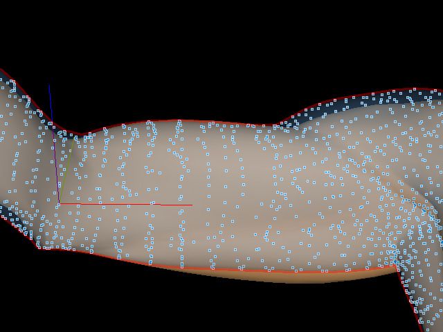
T. Rhee, J.P. Lewis, and U. Neumann / EG 2006

weights for each vertex are automatically computed from the         data for SSD and WPSD calculations, they have traditionally
sample poses. This can enhance the skinning quality not only        been manually generated by skilled artists. Least-squares
of SSD but also WPSD, since both methods require accurate           based vertex weight estimation was shown in the skinning
joint weight values.                                                methods [WP02, MTG03]. James et al. describe mesh based
                                                                    skinning including estimation of bone parameters and ver-
   The deformation required in WPSD and SSD is indepen-
                                                                    tex weights for each bone [JT05]. In their paper, the vertex
dent for each vertex and this per-vertex computation can be
                                                                    weights of each joint are calculated by NNLS (non-negative
parallelized in a SIMD architecture. The GPU is a general
                                                                    least squares) and we derive a similar approach to calculate
SIMD architecture having one-sided (unidirectional) com-
                                                                    weights for SSD and WPSD.
munication to texture memory. We demonstrate our parallel
WPSD method using GPU fragment processors. In our ex-                  In recent years, since the performance of GPUs has been
periments, we can speed up SSD, PSD, as well as WPSD                improving more rapidly than that of CPUs, and GPUs have
to around 20 times faster than on the CPU (from 1.2FPS to           many processing units serving as a SIMD parallel architec-
25FPS speed-up of WPSD on a detailed model having 22836             ture, many algorithms have been accelerated by GPU pro-
triangles with 11574 vertices) using a modern graphics card,        gramming [LHK∗ 04, PF05, GPG]. Deformation and skin-
thus making WPSD a feasible real-time skinning solution             ning algorithms can also be enhanced by GPUs and several
for various applications including games, virtual reality, and      papers have profited from this [JP02, KJP02, BK05, JT05].
other real-time simulations.
                                                                       However, in previous research, since vertex information
                                                                    cannot be accessed in the fragment program, GPU-based
2. Related work                                                     vertex deformation is usually performed by vertex programs.
Many commercial software packages generate skin defor-              In this paper, we develop a parallel WPSD method using the
mation arising from joint movement using a method known             fragment processors to gain greater parallelism and perfor-
as (linear blend) skinning, Skeletal Subspace Deformation           mance.
(SSD), enveloping, etc., based in part on work published by
                                                                       Person-specific data modeling and its deformation is also
Thalmann et al. [MTLT88]. SSD is based on the weighted
                                                                    an interesting topic in realistic articulated body simulation.
blending of affine transformations of each joint and used in
                                                                    Rhee et al. described human hand modeling from surface
many real-time applications due to its simple and fast com-
                                                                    anatomy of the person [RNL06]. Anguelov et al. developed
putation. However, it also exhibits some well known artifacts
                                                                    shape completion and animation of people, derived from the
such as skin that collapses around the joints at increasing
                                                                    set of range scan data and example based deformation in
bend angles, and a variety of solutions for these problems
                                                                    pose and shape space [ASK∗ 05].
have been published [Web00, WP02, MTG03, KZ05].
   Recently, example-based methods [LCF00, SRC01,                     Physically inspired skinning should be also recognized as
ACP02, KJP02, KM04] have permitted more complex                     another important area of articulated body animation. How-
skinning effects such as muscle bulges and major wrinkles,          ever, we entrust the review of the subject to the recent related
while also addressing the artifacts of simple algorithmic           papers [AHS03, CBC∗ 05, PCLS05, SNF05].
schemes. In these methods, a number of provided (scanned
or sculpted) samples of the desired skin shape are simply
interpolated based on the creature’s pose (and possibly addi-       3. Skin deformation
tional abstract control “dimensions”). These example-based
methods can also be considered as a non-parametric ap-              Example-based skinning problems can be described by the
proach to skin deformation. In common with non-parametric           following general equation,
sampling methods in texture synthesis (and more generally
in statistical regression), the amount of memory for these                                 v(pa ) = S(v0 + D(pa ))                            (1)
methods grows with the number of training samples, but
arbitrary distributions can be approximated.                           where pa is an arbitrary pose, v(pa ) is a vertex of a de-
   Some of the most impressive example-based results to             formed target surface of the arbitrary pose, v0 is an unde-
date are those of Kurihara and Miyata’s hand model derived          formed (rest pose) vertex, S is the SSD function, and D(pa )
from medical images [KM04]. Since acquiring 3D medi-                is a displacement as a function of the arbitrary pose.
cal images is relatively expensive, they developed weighted
                                                                       In skeletal subspace deformation the displacement D(pa )
pose space deformation (WPSD) to generate proper skinning
                                                                    is omitted and the target surface is calculated by SSD as
from a limited number of pose samples. They modify the dis-
                                                                    a blend of affine transforms of v0 [section 3.1]. Skinning
tance between poses using the joint weights of each vertex to
                                                                    methods related to PSD use the displacement of an arbitrary
provide a more appropriate distance measure for skinning.
                                                                    pose D(pa ), calculated by interpolation in pose space [sec-
  Although the joint weights for each vertex are important          tion 3.2].


                                                                                     c The Eurographics Association and Blackwell Publishing 2006.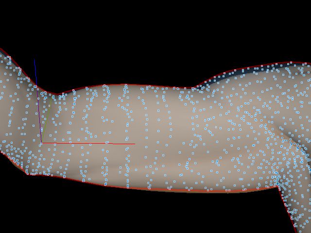
T. Rhee, J.P. Lewis, and U. Neumann / EG 2006

                              (a)                                             (b)                                                  (c)

                              (d)                                             (e)                                                  (f)
Figure 1: Skinning result of each algorithm: (a) SSD, (b) PSD, (c) WPSD, (d) Difference between SSD and PSD (blue dotted
area), (e) Difference between SSD and WPSD (blue dotted area), (f) Difference between PSD and WPSD (blue dotted area);
areas around blue and red arrows represent unexpected results of SSD and PSD respectively.

3.1. Skeletal subspace deformation (SSD)                                            sample vertex vk and the rest pose vertex can be calculated:
                                                                                                              n joint
SSD [MTLT88] is based on the weighted blending of an                                                 dk = ( ∑ w j T j )−1 vk − v0               (3)
affine transformation of each joint by equation 2.                                                             j=1
                                          n joint                                   where vk is a vertex in sample pose pk and dk is the displace-
                      va = S(v0 ) = ( ∑ w j T j )v0                     (2)         ment of this vertex relative to v0 in the sample pose pk ; the
                                           j=1                                      other variables are defined as in equation 2. Note that the
                                                                                    inverse here is of the weighted sum of affine transforms.
where n joint is the number of joints, va is a vertex in an
arbitrary pose pa , v0 is a vertex in the rest pose, and w j                           After defining the displacement of each pose, the dis-
is a joint weight that defines the contribution of joint j’s                        placement at an arbitrary pose can be calculated by RBF
transformations to the current vertex. The weight w j can                           (Radial Basis Function) [LCF00] or normalized radial basis
be assigned by the artist to control deformation and usu-                           function [KM04] interpolation of the example poses’ dis-
       n joint
ally ∑ j=1     (w j ) = 1.0. This simple algorithm is used in many                  placements.
commercial graphics packages and real-time rendering ap-
                                                                                      The displacement da of a vertex in an arbitrary pose pa
plications but shows several limitations, because the defor-
                                                                                    can be calculated as
mation of this method is restricted to the subspace of the                                                                   n pose
affine transformation of the joints [LCF00].                                                        da = D(pa ) =                ∑ rk (pa )dk   (4)
                                                                                                                              k=1
                                                                                    where n pose is the number of sample poses, da is a displace-
3.2. Pose space deformation (PSD)                                                   ment of the vertex in an arbitrary pose pa , and the weight
                                                                                    rk (pa ) defines the contribution of each sample pose.
If we have a sufficient set of examples to describe the move-
                                                                                       Normalized Radial Basis Functions can smoothly interpo-
ment of an articulated object, we can interpolate displace-
                                                                                    late pose space using:
ment in “pose space” [LCF00]. Each sample pose consists
                                                                                                                        n pose
of sample skin geometry and the related joint skeleton, and
a vector containing the joint angles represents the pose.
                                                                                                         ft (pa ) =     ∑ λ t,k φk (γk )        (5)
                                                                                                                        k=1

  If we translate each skinning sample k to the rest coordi-                        where ft (pa ) is the radial basis weight function for example
nate frame using inverse SSD, the displacement between the                          t evaluated at an arbitrary pose pa , n pose is the number of


c The Eurographics Association and Blackwell Publishing 2006.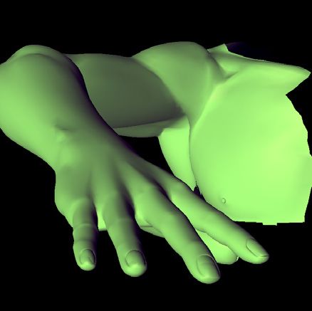
T. Rhee, J.P. Lewis, and U. Neumann / EG 2006

sample poses, λt,k are real valued weights between pose t                 (equation 8). In many applications, the weights are manually
and k, φk are the radial basis functions, and γk is the distance          generated by skilled artists and it is hard to generate accurate
between the pose pk and the arbitrary pose pa (defined as the             values when a number of joints are involved in deforming
Euclidian distance between the joint vectors of each pose).               a region. In this paper, we automatically calculate the joint
   The weight rk (pa ) is calculated using normalized RBFs                weights of each vertex from the sample poses to enhance the
and is used in equation 4 to calculate the displacement da of             accuracy of the weight value. This results in better skinning
a vertex in an arbitrary pose pa :                                        and reduces the elaborate manual work required to create
                                                                          weight maps.
                                     fk (pa )
                    rk (pa ) =    n pose                        (6)         In each sample pose pk , we have following equation based
                                 ∑t=1 ft (pa )
                                                                          on SSD:
                                                     −γ2
Gaussian radial basis functions φk (γk ) = exp( 2σ2k ) are one                                               n joint

possible choice of the basis and the constant σ can be speci-                                    ṽk − ek = ( ∑ w j T j )v0                         (9)
                                                                                                              j=1
fied experimentally [LCF00].
                                                                          where ṽk is a particular vertex from skin sample k, the right
                                                                          hand side is the SSD deformation of vertex v0 from the rest
3.3. Weighted pose space deformation (WPSD)
                                                                          pose, ek is a displacement between the SSD deformation and
WPSD is developed by Kurihara et al. [KM04] to deform                     ṽk , and the other variables are as in equation 2.
their example-based human hand model derived from med-
ical images. In the original PSD, the distance between two                   If we have sufficient examples involving the same set of
poses pa and pk having n joint number of joints for each pose             n joint joints, we have n pose equations of the form:
is defined as                                                                                                  n joint
                                                                                                 ṽk − ek = ( ∑ v j w j )                        (10)
                              n joint
                                                                                                               j=1
              γk (pa , pk ) =  ∑ (pa, j − pk, j )2       (7)
                                  j=1                                     where v j is v0 transformed by Tj . Although the ek is un-
                                                                          known, we can solve for weights that minimize the ek in
    In equation 7, since the γk is the difference of n joint -            a least squares sense by stacking the equations 10 (with ek
dimensional joint vectors of related poses, every vertex in               omitted) into a linear matrix system
the pose pk has same distance γk resulting in the same
                                                                                                       v − Aw2                                  (11)
weight rk (pa ) in every vertex of the pose pk . Further-
more, because each element of the joint vector equally con-               where w is a n joint -dimensional weight vector, v is a 3npose -
tributes to the distance calculation, two vectors having a                dimensional vector containing the vertex ṽi from every sam-
same value but different order generate same pose distance.               ple, and A is a 3n pose ×n joint matrix .
For example, three different joint vectors p1 = (θ, 0, 0), p2 =
                                                                             From equation 11, we can calculate w from the given
(0, θ, 0), p3 = (0, 0, θ) have same distance between them and
                                                                          value of v and A to reduce the error of this equation. We
it can cause unexpected results in PSD.
                                                                          use the non-negative least square (NNLS) method to solve
   In WPSD [KM04], Kurihara et al. modify the distance                    this problem and it determines positive weight values mini-
definition between poses using joint weight of each vertex                mizing error in equation 10. The calculated weight vector w
                                                                                                    n joint
i to give proper weight to each element of a joint vector,                is normalized to satisfy ∑ j=1    w j = 1.0.

                              n joint
                                                                           In order to avoid a singular matrix A, the number of poses
            γi,k (pa , pk ) =  ∑ wi, j (pa, j − pk, j )2  (8)            should be greater or equal to the number of overall DOF
                                 j=1                                      (Degree Of Freedom) of the joint vector (each joint has 3
where γi,k (pa , pk ) is the distance between pose pa and pk of           DOF), and the sample poses should be sufficiently different.
vertex i, and wi, j is weight of joint j of vertex i used in equa-           James et al. used a similar approach to estimate vertex
tion 2. From this definition, a more accurate pose distance is            weights in each joint [JT05] and we demonstrate their efforts
obtained and it generates better skinning in arbitrary poses,             in our skinning method.
especially when the poses are far from the examples.
   Figure 1 shows result of three different skinning methods,             5. Parallel deformation on GPU
but we entrust the detail comparison between quality of each
algorithm to their original papers [MTLT88,LCF00,KM04].                   Skinning deformations vary across vertices. In SSD and
                                                                          WPSD, this per-vertex computation is independent for each
                                                                          vertex and can be parallelized by a SIMD parallel architec-
4. Computing joint weights from samples                                   ture. We developed a parallel skinning algorithm for SSD
The joint weights of each vertex are important to generate                and WPSD that is suitable to GPUs having a SIMD archi-
accurate skinning in SSD (equation 2) as well as in WPSD                  tecture with one-side communication to texture memory.


                                                                                           c The Eurographics Association and Blackwell Publishing 2006.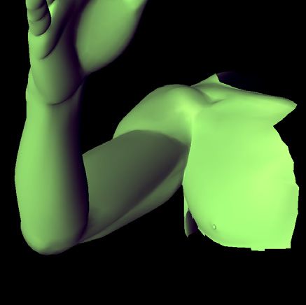
T. Rhee, J.P. Lewis, and U. Neumann / EG 2006

5.1. Parallel WPSD
The computation cost of the SSD skinning algorithm is
O(nvertex × n joint ) from equations 1, 2, PSD is O(nvertex ×
n joint × n pose ) from equations 1, 2, 4, and WPSD is
O(nvertex × n joint × n pose × n pose × n pose ) from equations 1,
2, 4, 5, 6. Where, computation cost of original PSD is de-
fined by equation 1, 2, 4, since ri is same in all vertices and
di can be pre-calculated.
   The number of joints n joint and poses npose can be reduced
to the smaller numbers using the method developed by Kry
et al. [KJP02], as will be discussed in section 5.2.1 with ef-
forts to reduce texture memory space.
   In previous research, the Eigenskin method based on PSD
                                                                                   Figure 2: Packing data into textures: texture map Ti can be
was developed using GPU vertex programming [KJP02].
                                                                                   Tv , Tn , Tw1 , Tw2 , and Td j . V(vertex), N(normal), W(weight),
The vertex program uses a relatively small number of slow
                                                                                   J(joint index), and D(displacement) represent each texel
processing units compared with the fragment processors,
                                                                                   (RGB(A)) value of the related texture. Td consist of eight Td j
and the per-vertex computation cost of the original PSD
                                                                                   storing displacements of each pose j.
is O(n joint × n pose ). Therefore WPSD, having higher per-
vertex computation cost O(n joint × n pose × n pose × n pose ),
can clearly benefit from parallel computation on fragment
processors.                                                                        in the texture maps. In general, the distribution of skin-
                                                                                   ning effects in an articulated body is local to several joints
5.2. Parallel WPSD on GPU                                                          [MMT97,KJP02], even in a region as complicated as a hand.
                                                                                   For example, deformations arising from the PIP (Proximal
We developed parallel skinning using the GPU fragment                              Interphalangeal) joint of index finger do not propagate to
processors and demonstrate our method using three render-                          the other fingers, and deformation on the middle phalanx of
ing passes. In order to minimize real-time computation, we                         index finger is only affected by the movement of PIP and
separate possible pre-calculation steps and save the results                       DIP(Distal phalanx) joints. From this observation, we can
into texture memory using texture maps. Because the value                          reduce joint weight storage from the actual number of joint
in the texture memory is not changed in the successive defor-                      n joint to a smaller number of “principal joints” ñ joint selected
mation, it can be pre-computed and stored in the read-only                         by sorting on the weight value. We threshold ñ joint at four in
texture memory.                                                                    our tests with an additional four elements to hold the related
   In the first and second pass, per-vertex deformation is cal-                    joint index. As a result, we can save the joint weights of en-
culated in the fragment program and the results are stored                         tire geometry in two RGBA textures Tw1 , Tw2 each with size
in texture maps using the FBO (Frame Buffer Object) exten-                         nvertex × 4(rgba) and store the entire information required
sion [Gre05]. These texture maps are bound to the geometry                         for SSD [equation 2] in four textures Tv , Tn , Tw1 , and Tw2 .
of the rest pose with their texture coordinates. In the third                          The displacement values calculated by equation 3 can be
pass, each vertex in the rest pose is changed by the deformed                      stored in n pose displacement textures; npose is the number of
vertex stored in the output texture generated in the first and                     sample poses. In case of complex joint structures and a large
second passes using vertex texture fetch.                                          DOF model, we need many sample poses to calculate ac-
                                                                                   curate joint weights and PSD deformation. However, since
5.2.1. Packing data into textures                                                  the joint weights can be pre-calculated, we can reduce the
                                                                                   number of sample poses needed in real-time PSD compu-
The fragment processors cannot access vertex information.
                                                                                   tation. PCA (Principal Component Analysis) of pose space
Instead, we can use texture memory to send data to the frag-
                                                                                   can yield an orthogonal basis called “ Eigendisplacement ”
ment program. Information needed in the fragment program
                                                                                   [KJP02]. If we reduce the size of pose space from npose to
is packed into texture maps and stored into texture memory.
                                                                                   ñ pose “principal poses” (ñpose < n pose ), we can reduce the
   Geometry information from the rest pose is stored into                          number of displacement textures. In our paper, we set ñpose
two RGB texture maps, a vertex texture Tv and normal tex-                          as eight in our experiment and save displacements of all
ture Tn ; each has size nvertex × 3. These textures represent                      poses into a RGB texture Td having size nvertex × 8(ñ pose ) ×
parameter v0 in equation 2 and each 3D element (x, y, z) is                        3(rgb).
stored into the (r, g, b) value of a texel [Figure 2].
                                                                                      Therefore, from the two important observations of “prin-
   The joint weights calculated in section 4 are also stored                       cipal joints” and “principal poses”, the original computation


c The Eurographics Association and Blackwell Publishing 2006.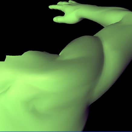
T. Rhee, J.P. Lewis, and U. Neumann / EG 2006

cost for SSD, PSD, and WPSD discussed in section 5.1 can                  cannot access vertex data in the fragment program, the ef-
be reduced using ñ joint and ñ pose rather than n joint and n pose .    ficiency of parallel computation on a fragment program is
                                                                          higher, since the fragment processor has more processing
   In the original PSD, since the weight ri in equation 4 is the
                                                                          units and each of them has more computation power than a
same at every vertex, we do not need to calculate this value
                                                                          vertex processor. The fragment processing system is a gen-
in the GPU. Since the size of this value is just ñ pose , we can
                                                                          eral SIMD architecture using fragment streams as input data;
simply pass them to the GPU as parameters without gener-
                                                                          each fragment is assigned to a fragment processor to calcu-
ating a texture map. Therefore, we store all the information
                                                                          late its final color value independently and in parallel.
needed to calculate the original PSD at this point.
                                                                             We developed a parallel WPSD algorithms using the frag-
    In order to reduce real-time computation, we pre-calculate
                                                                          ment processors to enhance the extent of parallel compu-
T j in equation 2 and λ in equation 5 and store them into
                                                                          tation. Geometry information like vertex positions and nor-
another one channel texture Tx having size ñpose × (ñ pose +
                                                                          mals are stored in texture maps Tv and Tn as described in
ñ joint × 3(x, y, z)).
                                                                          section 5.2.1 and the vertex information is referred in the
    As a result, we store all the variables required to                   fragment processors to calculate final color values.
calculate WPSD, PSD, and SSD in six texture maps:                            In order to assign each vertex value stored in a texture
Tv , Tn , Tw1 , Tw2 , Td , and Tx . The values in the texture maps        map to a fragment, we bind the geometry texture Tv or Tn
are stored in the texture memory at setup time, since they                to a quad and render it using an orthographic camera having
are not changed during the deformation process.                           the same width and height as the quad. Furthermore, since
   In current graphic card architectures, data transfer from              the viewport is set to the same resolution as the textures,
CPU to GPU is slow compared with memory access within                     each fragment is exactly matched with each texel holding the
the GPU. Since the only data changed in each deformation                  vertex information, and we can access each vertex using the
and passed from CPU to GPU is a joint vector pa (size =                   texture coordinates of the fragment; vertex weights and dis-
n joint ) representing the current arbitrary pose, the memory             placements stored in the texture maps can also be accessed
access rate in our method is very efficient; In the original              by similar methods.
PSD method, an additional rk value (size = ñ pose ) is required.           A similar idea was developed in [PBMH02] to calculate
                                                                          ray tracing in a fragment program and is used in GPGPU
5.2.2. Configurations for fragment program                                (General Purpose computation on GPUs) applications [GPG,
                                                                          LHK∗ 04, PF05].
                                                                             The FBO (Frame Buffer Object) extension [Gre05] sup-
     Variables: Tout = output texture, Tv = vertex texture
                                                                          ports rendering into an attached texture. This saves memory
 1   /* Set orthographic camera with same size of quad */;                and time, since there is no copy operation from frame buffer
 2       gluOrtho2D(-1, 1, -1, 1);                                        to texture buffer. We implemented our WPSD algorithm us-
 3       bind(FBO);                                                       ing the fragment program with the FBO extension to store
 4   /* Bind Tout and set to FBO drawbuffer */;                           the result directly into texture maps accessed by vertex pro-
 5       bind(Tout ), SetFBOdrawbuffer(Tout );                            gram in the next pass. A summary of this method is shown
 6       bind(Tv );                                                       in Algorithm 1.
 7       enable(fragment program);
 8   /* Set viewport to the resolution of the texture */;
                                                                          5.3. GPU implementation
 9       glViewport(0, 0, texWidth, texHeight);
10   /* Render a quad into Tout using FBO */;                             We implemented GPU deformation using three rendering
11        glBegin(GL_QUADS);                                              passes, and the basic architecture is described in figure 3.
12        { glTexCoord2f(0, 0); glVertex3f(-1, -1, -0.5f);
                                                                             In the first pass, we parallelize per-vertex deformation us-
13            glTexCoord2f(1, 0); glVertex3f( 1, -1, -0.5f);
                                                                          ing GPU fragment processors. The data required to calculate
14            glTexCoord2f(1, 1); glVertex3f( 1, 1, -0.5f);
                                                                          this deformation is stored in the textures as described in sec-
15            glTexCoord2f(0, 1); glVertex3f(-1, 1, -0.5f);
                                                                          tion 5.2.1 and the deformation for each vertex is calculated
16       };
                                                                          in a fragment processor. In a given arbitrary pose defined by
17        disable(fragment program);
                                                                          a joint vector, SSD is computed by equation 2 using texture
Algorithm 1: Configuration of fragment program for ver-                   maps Tv , Tw1 , Tw2 and Tx ; refer to the texture map notation in
tex refering and direct rendering into texture                            section 5.2.1. PSD is computed by equation 4 using Td , Tx ,
                                                                          after calculating rk (pa ) by equation 6. In the case of WPSD,
                                                                          the weighted distance is computed by equation 8 using Tw1 ,
   Since vertex information cannot be accessed by the frag-
                                                                          Tw2 , and Tx .
ment program, vertex deformation on a GPU is usually per-
formed by a vertex program [KJP02, BK05]. Although, we                       In the first pass, the result of the deformation is rendered


                                                                                           c The Eurographics Association and Blackwell Publishing 2006.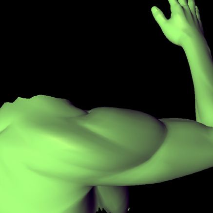
T. Rhee, J.P. Lewis, and U. Neumann / EG 2006
vertices [Figure 4]. Note that these models are considerably
more detailed than those used in current games, so the re-
ported frame rates would be much higher if typical game-
resolution models were used. On the other hand, with the
expected growth of GPU processing power, models such as
these will be in wide use in a few years, and algorithms such
as WPSD will be required to produce realistic deformations
at this level of resolution.
Figure 3: Overview of WPSD on GPU: Each Ti is the texture
map storing the required data for the calculation (refer to
section 5.2.1 for their values) , Ti s are the texture maps to
store the output of the 1st and 2nd passes, P0 is the geometry
in the rest pose, and Pa is a deformed model in an arbitrary
pose.
into a texture map Tv , using the FBO, and passed to the
third pass. In the second pass we calculate and store normal
deformation with a similar method as in the first pass, and
the results are stored in the texture map Tn .
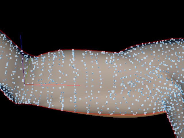
In the third pass, using a vertex program, each vertex of Figure 4: Mesh of test data: the top row is a low-resolution
the rest pose is transformed to the final deformed position us- mesh, the second row is a mid-resolution mesh, and the bot-
ing the information from the texture maps computed in the tom row is a high-resolution mesh
previous two passes. In order to access related texture infor-
mation in each vertex, we created texture coordinates of each Eight sample poses were created by Poser [Cur] and the
texel in pre-processing and used them in the vertex program. joints weights and displacements of each sample were de-
Specifically, the two texture maps, Tv and Tn that are gener- rived from these models [Figure 5].
ated in the first and second passes are accessed in the vertex
program using the texture coordinate of the current vertex. Our parallel algorithm is based on three pass GPU com-
putation. The fragment program for the 1st and 2nd pass,
Alternatively, multiple render targets (MRTs) can com-
and the vertex program for the 3rd pass are implemented in
bine the first and second pass, and vertex buffer objects the Cg language [FK03]. For accuracy the GPU computation
(VBOs) could be used to render the deformed results back is performed by 32bit floating point operations with 32bit
to the vertex array [OPE, GPG, LHK∗ 04].
floating point texture maps. Table 2 shows the total memory
space to store texture maps required by the fragment pro-
6. Results gram. Note that the maximum required memory space for
the highest resolution model is just 6.8 Mbytes; the size of
We tested our methods using upper arm models consisting
the output texture Tv and Tn is the same as the size of Tv
of four joints (collar, shoulder, elbow, and wrist). Each has
and Tn .
three DOF and the wrist is the end joint having no DOF.
Three different resolution meshes are used to test the per- The results of GPU-based deformation for SSD, PSD, and
formance of GPU parallel computation: the high-resolution WPSD are shown in Figure 1 and 6, and the experiment is
model has 91460 triangles with 46036 vertices, the mid- performed in a GeForce 6800 Ultra GPU and a 3.4Ghz Pen-
resolution model has 22836 triangles with 11574 vertices, tium 4 CPU. The timing results of each algorithm on the
and the low-resolution model has 5762 triangles with 2972 CPU and GPU are summarized in table 1.
c The Eurographics Association and Blackwell Publishing 2006.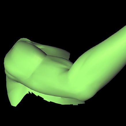
T. Rhee, J.P. Lewis, and U. Neumann / EG 2006

   On average, our GPU-based deformation shows around
20 times speed-up compared with CPU-based deformation.
GPU-based WPSD has roughly the same speed as CPU-
based SSD. Therefore, real-time applications using SSD can
substitute WPSD running on the GPU without loosing their
real-time performance. Since our algorithm shows speed-up
for SSD and PSD as well as WPSD, applications can choose
the most appropriate skinning method according to the re-
quired deformation and detail.

      Method      Mesh      CPU(FPS)      GPU(FPS)
      SSD          low          150            1425
                  middle        39              630
                   high          5              164
      PSD          low          98             1230
                  middle        23              530
                   high         4.5             140
      WPSD         low           5              85
                  middle        1.2             25
                   high        0.29              7

Table 1: Timing results (in FPS) of each algorithm: the low-
resolution mesh has 5762 triangles with 2972 vertices, the
mid-resolution mesh has 22836 triangles with 11574 ver-
tices, and the high-resolution mesh has 91460 triangles with
46036 vertices.
                                                                       Figure 6: Arbitrary poses deformed by WPSD on GPU

 Vertices         Tv &Tn    Tw1 &Tw2      Td         Tx   Tot
                                                                       Articulated body skinning using SSD, PSD, and WPSD
 2972 (low)       35×2        46×2        278         1   441       are efficiently parallelized by our GPU-based method, and
 11574 (mid)      135×2      180×2       1080         1   1711      on a detailed model, we obtain around 20 times speed-up
                                                                    compared with CPU-based computation.
 46036 (high)     539×2      719×2       4315         1   6832
                                                                       Principal component compression of the examples and
                                                                    careful analysis of joint distributions can reduce the domain
Table 2: Texture memory to store data required in fragment
                                                                    of computation [KJP02] and other algorithms based on the
program (in Kbytes); refer to section 5.2.1 for texture nota-
                                                                    SSD, PSD, and shape interpolation may be parallelized on
tion .
                                                                    GPU using our approach.

7. Conclusions
                                                                    Acknowledgments
In this paper, we present a parallel skinning algorithm suit-
able for SIMD architectures such as GPUs. The joint weights         This research has been funded by the Integrated Media Sys-
of each vertex are automatically computed by NNLS and               tem Center/USC, and Samsung Electronics. We wish to
used in the skinning computation for SSD and WPSD.                  thank KyungKook Park, Changki Min, and Tim Foley for
                                                                    discussions about GPUs, and the anonymous reviewers for
   Independent per-vertex deformation is parallelized on the        their sincere comments.
GPU using three rendering passes. In the first and second
passes, per-vertex deformation is calculated by the fragment
                                                                    References
processors and the results are stored in texture maps using
FBO. In the third pass, using vertex processors, each vertex        [ACP02] A LLEN B., C URLESS B., P OPOVIć; Z.: Artic-
of the rest pose is changed by the deformed vertex stored in          ulated body deformation from range scan data. In SIG-
the textures generated by the first and second passes.                GRAPH ’02: Proceedings of the 29th annual conference


                                                                                     c The Eurographics Association and Blackwell Publishing 2006.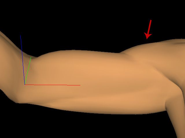
T. Rhee, J.P. Lewis, and U. Neumann / EG 2006

Figure 5: Samples poses and displacements: the first row shows each sample poses, the second row shows displacement of each
sample pose with the rest pose in the first column of the third row. Please enlarge to see details.

   on Computer graphics and interactive techniques (New                              tive techniques (New York, NY, USA, 2002), ACM Press,
   York, NY, USA, 2002), ACM Press, pp. 612–619.                                     pp. 582–585.
[AHS03] A LBRECHT I., H ABER J., S EIDEL H. P.: Con-                               [JT05] JAMES D. L., T WIGG C. D.: Skinning mesh ani-
  struction and animation of anatomically based human                                mations. ACM Trans. Graph. 24, 3 (2005), 399–407.
  hand models. In Proceedings of the 2003 ACM SIG-                                 [KJP02] K RY P. G., JAMES D. L., PAI D. K.: Eigen-
  GRAPH/Eurographics Symposium on Computer Anima-                                    Skin: Real time large deformation character skinning in
  tion (SCA-03) (2003), pp. 98–109.                                                  hardware. In Proceedings of the 2002 ACM SIGGRAPH
[ASK∗ 05] A NGUELOV D., S RINIVASAN P., KOLLER D.,                                   Symposium on Computer Animation (SCA-02) (2002),
  T HRUN S., RODGERS J., DAVIS J.: Scape: shape com-                                 pp. 153–160.
  pletion and animation of people. ACM Trans. Graph. 24,                           [KM04] K URIHARA T., M IYATA N.: Modeling de-
  3 (2005), 408–416.                                                                 formable human hands from medical images. In Proceed-
                                                                                     ings of the 2004 ACM SIGGRAPH Symposium on Com-
[BK05] B OTSCH M., KOBBELT L.: Real-time shape edit-
                                                                                     puter Animation (SCA-04) (2004), pp. 357–366.
  ing using radial basis functions. Computer Graphics Fo-
  rum 24, 3 (2005), 611–621. (Proceedings of Eurographics                          [KZ05] K AVAN L., Z ARA J.: Spherical blend skinning:
  2005).                                                                             A real-time deformation of articulated models. In 2005
                                                                                     ACM SIGGRAPH Symposium on Interactive 3D Graphics
[CBC∗ 05] C APELL S., B URKHART M., C URLESS B.,                                     and Games (April 2005), ACM Press, pp. 9–16.
  D UCHAMP T., P OPOVIć; Z.: Physically based rigging
                                                                                   [LCF00] L EWIS J. P., C ORDNER M., F ONG N.: Pose
  for deformable characters. In SCA ’05: Proceedings of
                                                                                     space deformation: a unified approach to shape interpo-
  the 2005 ACM SIGGRAPH/Eurographics symposium on
                                                                                     lation and skeleton-driven deformation. In SIGGRAPH
  Computer animation (New York, NY, USA, 2005), ACM
                                                                                     ’00: Proceedings of the 27th annual conference on Com-
  Press, pp. 301–310.
                                                                                     puter graphics and interactive techniques (New York,
[Cur] C URIOUS L AB:                    Poser 6.                http://www.          NY, USA, 2000), ACM Press/Addison-Wesley Publishing
  curiouslabs.com.                                                                   Co., pp. 165–172.
[FK03] F ERNANDO R., K ILGARD M. J.: The Cg Tuto-                                  [LHK∗ 04] L UEBKE D., H ARRIS M., K RUGER J., P UR -
  rial; The Definitive Guide to Programmable Real-Time                               CELL T., G OVINDARAJU N., B UCK I., W OOLLEY C.,
  Graphics. Addison-Wesley, 2003.                                                    L EFOHN A.: Gpgpu: general purpose computation on
                                                                                     graphics hardware. In GRAPH ’04: Proceedings of the
[GPG] GPGPU: General-purpose computation using                                       conference on SIGGRAPH 2004 course notes (New York,
  graphics hardware. http://gpgpu.org.                                               NY, USA, 2004), ACM Press, p. 33.
[Gre05] G REEN S.:    The OpenGL Framebuffer Ob-                                   [MMT97] M OCCOZET L., M AGNENAT-T HALMANN N.:
  ject Extension. Game Developers Conference, 2005.                                  Dirichlet free-form deformations and their application to
  http://developer.nvidia.com/object/gdc_2005_                                       hand simulation. In Computer Animation (1997).
  presentations.html.
                                                                                   [MTG03] M OHR A., T OKHEIM L., G LEICHER M.: Di-
[JP02] JAMES D. L., PAI D. K.: Dyrt: dynamic response                                rect manipulation of interactive character skins. In SI3D
   textures for real time deformation simulation with graph-                         ’03: Proceedings of the 2003 symposium on Interactive
   ics hardware. In SIGGRAPH ’02: Proceedings of the 29th                            3D graphics (New York, NY, USA, 2003), ACM Press,
   annual conference on Computer graphics and interac-                               pp. 27–30.


c The Eurographics Association and Blackwell Publishing 2006.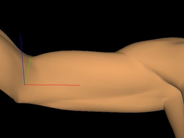
T. Rhee, J.P. Lewis, and U. Neumann / EG 2006

[MTLT88] M AGNENAT-T HALMANN N., L APERRIÈRE
  R., T HALMANN D.: Joint–dependent local deformations
  for hand animation and object grasping. In Graphics In-
  terface ’88 (June 1988), pp. 26–33.
[OPE] OPENGL: Opengl extension registry. http://
  oss.sgi.com/projects/ogl-sample/registry/.
[PBMH02] P URCELL T. J., B UCK I., M ARK W. R.,
  H ANRAHAN P.: Ray tracing on programmable graph-
  ics hardware. ACM Transactions on Graphics 21, 3 (July
  2002), 703–712. ISSN 0730-0301 (Proceedings of ACM
  SIGGRAPH 2002).
[PCLS05] P RATSCHER M., C OLEMAN P., L ASZLO J.,
  S INGH K.: Outside-in anatomy based character rig-
  ging. In SCA ’05: Proceedings of the 2005 ACM SIG-
  GRAPH/Eurographics symposium on Computer anima-
  tion (New York, NY, USA, 2005), ACM Press, pp. 329–
  338.
[PF05] P HARR M., F ERNANDO R.: GPU Gems 2; Pro-
  gramming Techniques for High-Performance Graphics
  and General-Purpose Computation. Addison-Wesley,
  2005.
[RNL06] R HEE T., N EUMANN U., L EWIS J.: Human
  hand modeling from surface anatomy. In I3DG ’06:
  Proc. of ACM SIGGRAPH Symposium on Interactive 3D
  Graphics and Games (2006).
[SNF05] S IFAKIS E., N EVEROV I., F EDKIW R.: Au-
  tomatic determination of facial muscle activations from
  sparse motion capture marker data. ACM Trans. Graph.
  24, 3 (2005), 417–425.
[SRC01] S LOAN P.-P. J., ROSE C. F., C OHEN M. F.:
  Shape by example. In SI3D ’01: Proceedings of the 2001
  symposium on Interactive 3D graphics (New York, NY,
  USA, 2001), ACM Press, pp. 135–143.
[Web00] W EBER J.: Run-time skin deformation. In In
  Proceedings of Game Developers Conference (2000).
[WP02] WANG X. C., P HILLIPS C.:            Multi-weight
  enveloping: least-squares approximation techniques for
  skin animation. In SCA ’02: Proceedings of the 2002
  ACM SIGGRAPH/Eurographics symposium on Computer
  animation (New York, NY, USA, 2002), ACM Press,
  pp. 129–138.


                                                                                  c The Eurographics Association and Blackwell Publishing 2006.
You can also read