Real World Results from a Signal Measurement Drone - Presented by Ian Gair SixArms
←
→
Page content transcription
If your browser does not render page correctly, please read the page content below
Real World Results from a Signal
     Measurement Drone

       Presented by Ian Gair
                SixArms
         IEEE BTS October 2017

                                   1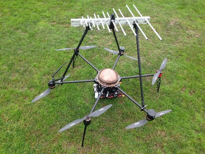
Outline of this Presentation

What we are measuring
Quick recap of Drone Based measurements
Case Studies:
  1)   Main feeders cut to the wrong lengths
  2)   Mechanical lean – storm damage
  3)   Panel Orientation incorrect
  4)   Inverted Panel
  5)   Adjacent tower or structure effects
  6)   Measuring in the near field

                                               2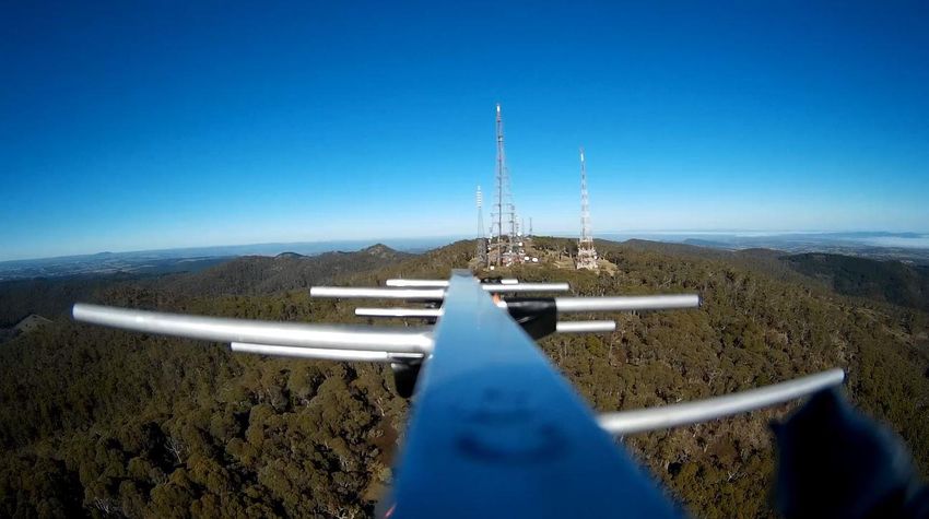
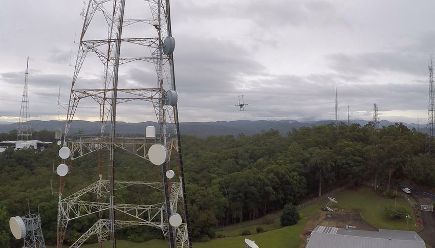
What are we measuring

                   Broadcast TV Antennas
                   mounted on towers or
                   masts.
                                           3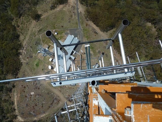
Typical Broadcast Antenna
High Power – can be several MegaWatts Radiated Power
High EMR levels – personnel and equipment can’t get
close
High gain
Antenna split into an Upper and Lower Half for
redundancy reasons – 2 main feeders needed
Narrow vertical beamwidths
Typically 4 faces of 12 panels with each panel having 4
horizontal dipoles = 48 elements on 4 faces giving 192
dipoles.
Typically 50 feet high and 600 feet above the ground
                   What could go wrong?

                                                          4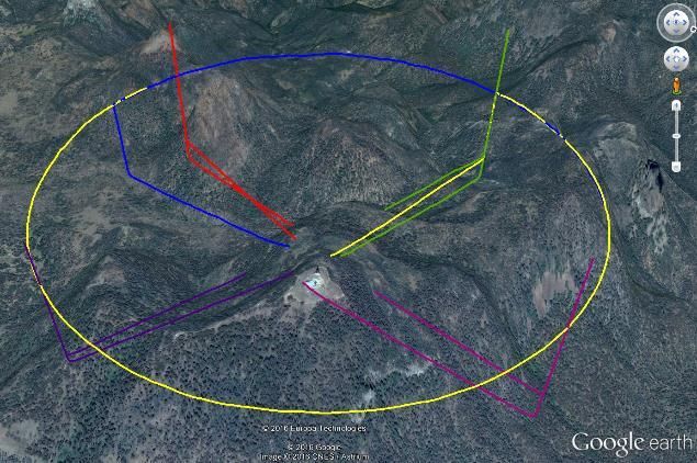
What & why are we measuring

• We need to measure antennas radiated power to
  verify they are operating as they were designed to.
• Antennas transmit power in all directions, ie 3D
• Measuring a horizontal slice and vertical slice gives
  us a very good picture of the power level and
  direction
• These slices are called the Horizontal Radiation
  Pattern (HRP) and Vertical radiation Pattern (VRP)

                                                          5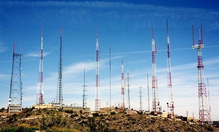
Typical EME levels extend
out to 1000 feet

  300m or 1000’

                            6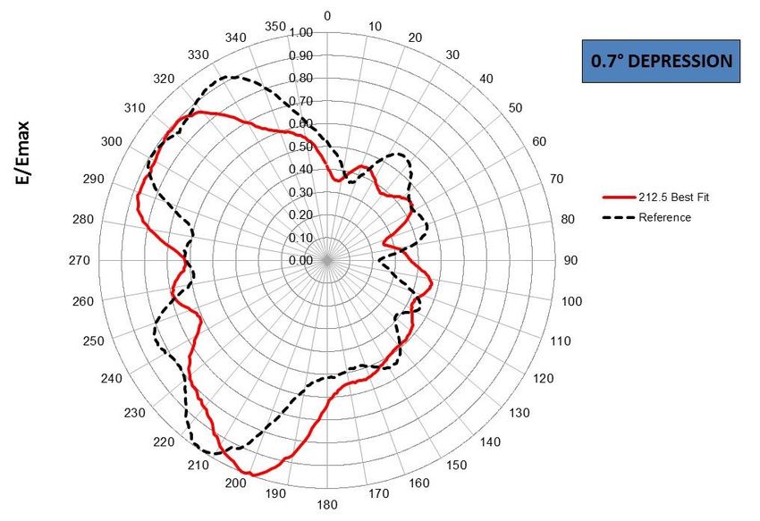
Example of a VRP

                   7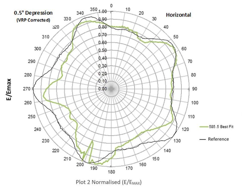
Example of an HRP

   Example of a HRP

                      8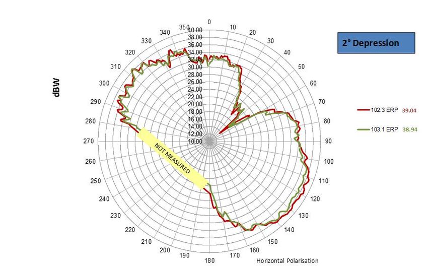
Measurement technique

Hardware consists of:
    • UAV with antenna
    • Integrated Spectrum
      Analyser and PC
    • High Resolution GPS
    • Telemetry to GCS
• Pre-flight Software - flight path – pre-programs the
  drones auto pilot with the appropriate flight path
  for the specific antenna
• Software driven capture, display and logging of
  data                                                9
Airborne Measuring Software

Other than data logging the software:
• Discards invalid data – due to excessive yaw, pitch or
  roll. The drone measuring antenna needs to point to at
  the Antenna Under Test (AUT)
• Calculates the distance between drone and AUT
• Calculates pathloss and applies correction and
  calibration factors
• Determines the absolute power and plots it on a results
  template
• Gives Preliminary results are available to the operator
  live via the link to the ground station

                                                        10
Methodology (1 of 2)
• Determine the position of the Antenna Under Test
(AUT) accurately
• GPS location and height above mean seal level.
• Determine the height of the AUT
• Use a Theodolite or tower drawings
• Determine the far field distance (>2D^2/lamda)
• As a rule of thumb with large arrays for FM 450 feet, VHF TV
1200 feet and UHF 1800 feet from the antenna
• Program the VRP runs –
• one per face of panels (typically 4 faces)
• over a range of 10 degrees above to below the horizon but as
low as practical
11Methodology (2 of 2)
• Fly the VRP runs in the far field and
• determine the angle of peak power (typically 1
degree below the horizon)
• Fly an HRP run in the far field at the angle of peak
power (typically 1 degree below the horizon)
12Typical Accuracy
Absolute is ±2.0 dB
Relative is better at ±1.3 dB
13Case Study 1 - Main feeders
cut to the wrong length
Most large antenna systems have 2 or 4 feeders from
the transmitter to the antenna for redundancy
reasons.
Antennas are separated in halves or quarters each
with it’s own feeder.
The relative length of these feeders is critical.
Incorrect lengths will result in beam tilt up or down.
VRP will show this, with same effect will be seen on
all faces.
14Case Study 1 - Main feeders
cut to the wrong length
15Case Study 2 - Mechanical lean
storm damage
Large UHF TV arrays have a small vertical beam width
Less than 2 degrees typically
A small mechanical lean or “banana-ing” can result in
excessive uptilt on one side and down tilt on the
other.
Rigging teams may not pick up the small deflection
Theodolites may not detect it if the antenna is
housed inside a protective radome.
VRP measurement will show the problem.
16Case Study 2 - Mechanical lean
storm damage
17Case Study 3 - Panel
Orientation incorrect
Large UHF antennas can consist of dozens of panels
on multiple faces.
Occasionally during installation an error can occur
Panels can be installed on the incorrect bearing
The HRP will show this.
18Case Study 3 - Panel
Orientation incorrect
19Case Study 4 – Inverted Panel
Large UHF/VHF antennas can consist of dozens of
panels on multiple faces.
Occasionally during installation an error can occur
Panels can be inverted (upside down).
The HRP and the VRP of the affected face will show
this
20Case Study 4 – Inverted Panel
21Case Study 5 – Adjacent tower
or structure effects
Other nearby structures affect the antenna pattern
22Case Study 5 – Adjacent tower
or structure effects
• 5 sided array
• Black trace is
the design
• Green trace is
measured
• Adjacent tower
(650 feet away)
at 200 degress
puts in a 3dB
notch
23Case Study 5 – Adjacent tower
or structure effects
• Red and Blue
traces are
measured
• Adjacent
structures at
160 Degrees
(170 feet away)
and 190
Degrees (540
feet away)
• 7dB and 4dB
notches 24Case Study 5 – Adjacent tower
or structure effects
What would the patterns of some these look like?
25Case Study 6 – Measuring in
the near field
We measure the electric field to derive the power
This is accurate enough when in the far field but
sometimes due to restrictions we can’t fly in the far field.
Flying inside the near field gives a wider arc of the VRP
but less accurate magnitude.
• Antenna – 4 faces of 16 panels.
• Frequency – 662.5MHz
• Far field distance using 2D^2/lamda is 1,400m (4,600 ft)
• Plot below shows results at 300m (1,000 ft), 600m
(2,000 ft), 1,150m (3,800 ft) and 1,600m (5,250 ft).
26Case Study 6 – Measuring in
the near field
In this case we can say that with a Far Field distance of
1,400m (4,600 ft), measurements at 600m (2,000 ft)
from the antenna still provide meaningful results.
27Any Questions?
And for more information go to:
www.sixarms.com
Or contact:
Ian Gair
Director / RF Engineer
Sixarms Pty. Ltd.
m: +61 417 402 767
e: ian@sixarms.com
28You can also read