Recent Advances in Turning Processes Using Coated Tools-A Comprehensive Review - MDPI
←
→
Page content transcription
If your browser does not render page correctly, please read the page content below
Review

Recent Advances in Turning Processes Using Coated
Tools—A Comprehensive Review
Vitor F. C. Sousa and Francisco J. G. Silva *
 ISEP—School of Engineering, Polytechnic of Porto, 4200‐072 Porto, Portugal; vcris@isep.ipp.pt
 * Correspondence: fgs@isep.ipp.pt; Tel.: +35‐122‐834‐0500

 Received: 13 December 2019; Accepted: 20 January 2020; Published: 23 January 2020

 Abstract: Turning continues to be the largest segment of the machining industry, which highlights
 the continued demand for turned parts and the overall improvement of the process. The turning
 process has seen quite an evolution, from basic lathes using solid tools, to complex CNC (Computer
 Numerical Control) multi‐process machines, using, for the most part, coated inserts and coated
 tools. These coatings have proven to be a significant step in the production of high‐quality parts and
 a higher tool life that have captivated the industry. Continuous improvement to turning coated tools
 has been made, with many researches focusing on the optimization of turning processes that use
 coated tools. In the present paper, a presentation of various recently published papers on this subject
 is going to be made, mentioning the various types of coatings that have recently been used in the
 turning process, the turning of hard to machine materials, such as titanium alloys and Inconel, as
 well as the interaction of these coatings with the turned surfaces, the wear patterns that these
 coatings suffer during the turning of materials and relating these wear mechanisms to the coated
 tool’s life expectancy. Some lubrication conditions present a more sustainable alternative to current
 methods used in the turning process; the employment of coated tool inserts under these conditions
 is a current popular research topic, as there is a focus on opting for more eco‐friendly machining
 options.

 Keywords: machining; turning process; turning tools; solid tools; cemented carbide; coated tools;
 coated cemented carbide; Physical Vapor Deposition (PVD); Chemical Vapor Deposition (CVD);
 multilayered coatings; nanolayered coatings; wear mechanism; tool life; minimum quantity
 Lubricant (MQL); cutting forces

1. Introduction
     The machining industry has seen a significant growth in the past 5–6 years, and it is projected to
be a 100 billion USD industry by 2025 [1]; this is primarily due to the high demand for higher quality
products and computer numerical control machines (CNC), that enable manufacturers to develop
these high quality and complex products at higher speeds [2]. Nowadays, there are 6‐axis CNC
machines, capable of turning feedstock bars into a complete product, which are quite appellative to
the machining industry [3]. Moreover, the lathe and milling segment are still leading the market. In
2018, the lathe segment was leading the market, valued at 17.65 billion USD, followed by the milling
segment [4]. The lathe market has grown significantly and is expected to keep growing in the
following years [5].
     The turning process can be described as the machining of a piece of material that is rotating,
using a single pointed tool that is stationary, to produce a smooth and straight outside or inside
radius on the piece. When turning, some considerations need to be taken into attention, such as the
type of turning that is being made, for example longitudinal turning, and external or internal turning;
quality demands, such as surface finish or tolerance must also be taken into consideration, because

Metals 2020, 10, 170; doi:10.3390/met10020170                                    www.mdpi.com/journal/metals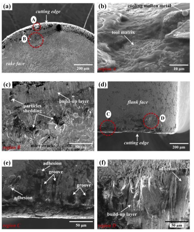
Metals 2020, 10, 170                                                                               2 of 28

these are factors that depend on the material that is being machined, as well as the tools and the
machine that is being used [6]. As previously stated, the tools used for turning are single‐pointed,
and can be categorized into solid tools and insert tools; these tools can be coated to improve the
process. Turning was initially carried out on a lathe, but the processes have seen significant evolution,
particularly due to the development of computer numerical control (CNC) machines from the 1980s
onwards, as well as turning centers, and later machining centers that could employ different
processes such as turning and milling. This led to an increase in their use in the manufacturing
industry [7], evolving from basic lathes, to multiple‐process machining centers.
      As the machines for turning evolved, so did the tools that were being used in the process, from
solid tools with simple geometries, usually made out of steel, to coated cemented carbide tools, that
make up to 80% of all tool inserts used in today’s machining. These coated cemented carbide tools
have improved the machining process significantly by enabling the machining of materials at faster
rates than using conventional, uncoated tools [8,9]. These coatings are deposited on the surface of the
tool to provide more wear resistance or a lower friction coefficient—in summary, these coatings
provide a way to machine materials at higher speeds, while maintaining overall good surface quality
and, especially, improving tool life, by reducing cutting forces, temperature and tool wear. There
have been recent developments in cemented carbide tools, fabricating these tools with gradient
layers, where the outer layers are, for example, harder than the substrate [10]. The fabrication of these
gradient composite tools will provide tools with more versatility, as the desired properties can be
applied on the base tool and improved on the surface, increasing their performance. Studies have
been made to analyze the way the thickness of these gradient layers affect the properties of these
tools [11]. A study carried out by Zhou et al. [12], tested different gradient cemented carbides, with
layers of differing thicknesses, and has tested these with different coatings in the high speed cutting
of a titanium alloy. Thus, Zhou et al. found that the thickness of the gradient layer’s influences cutting
performance, and that this thickness can be controlled by altering the contents of the cemented
carbide constituents. Additionally, the authors concluded that the carbide with the thickest layer had
the best cutting performance, making the control of these thicknesses very appealing when dealing
with this type of substrate.
      Coatings can be obtained using two different processes, either by Chemical Vapor Deposition
(CVD), or by Physical Vapor Deposition (PVD). CVD films are achieved by having a precursor
pumped inside a reactor; this precursor is regulated by control valves. The precursor molecules pass
by the substrate and are deposited on its surface, achieving a thin, hard coating. This process runs at
high temperatures, reaching temperatures of up to 900 °C and, additionally, the film thickness is
usually uniform throughout the substrate surface. PVD consists of different methods, such as
evaporation, sputtering and molecular beam epitaxy (MBE). In the sputtering technique, the applied
coating is achieved by placing a magnetron near the target, in a vacuum. Then, an inert gas is
introduced, then a high voltage is applied between the target and the substrate, releasing atomic size
particles from the target. These particles are projected onto the substrate and they start to form a solid
film. In the evaporation technique, the target acts as an evaporation source, having the material to be
deposited, which works as a cathode. The material is heated at a high vapor pressure, which causes
the release of the particles. The pumped gas, inserted in the reactor, clashes with the nano particles,
which causes the acceleration of these particles, which in turn creates a plasma. This plasma proceeds
trough the deposition chamber, thus depositing the coating’s layers onto the substrate. Usually, PVD
processes, when compared to CVD, run at a lower temperature (under 500 °C), and are more
environmentally safe due to the type of precursors used in the CVD process, which are toxic.
Additionally, the energy consumption of the PVD process is considerably lower than that of the CVD
process [13–16].
      Regarding the PVD process, there are various methods that can be used to obtain different
coatings, either in composition or with different properties. Some of these methods are quite novel,
or are seeing a new use in order to obtain certain coatings. As previously mentioned, the various
methods that are applied in the coating industry are either sputtering or evaporation methods.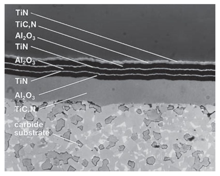
Metals 2020, 10, 170                                                                             3 of 28

Magnetron sputtering and arc evaporation methods have seen recent use in the deposition of
coatings. Figure 1 shows the various PVD methods.

      Figure 1. Different physical vapor deposition (PVD) techniques that are used currently in the
      production of advanced coatings [16].

      The most used method, for magnetron sputtering PVD coating, is the direct current method
(DC), however there are many more (as seen in the previous image), such as unbalanced magnetron
sputtering (UBMS) and the novel high‐power impulse/pulse magnetron sputtering
(HiPIMS/HPPMS). Regarding these sputtering methods, there is a recent paper, that presents a
method on how to control the boron‐to‐titanium ratios of TiBx thin films. The authors show, in this
paper, that the addition of an external magnetic field during the strongly magnetically unbalanced
magnetron sputtering of a TiB₂ target in Ar, enables the ability to control the ratio of B/Ti. This
research paves the way for synthesizing stoichiometric single‐crystal transition‐metal diborides [17].
Still regarding magnetron sputtering, a paper by Romero et al. [18] studies the properties of
TiAlN/TaN nanostructured coatings deposited by DC magnetron sputtering. These coatings were
deposited at different substrate rotation speeds. These different rotation speeds enable the control of
the coating’s architecture and mechanical properties. Recent studies on the HiPIMS reveal interesting
results, such as having better coating adhesion or even having better coating mechanical properties.
This paper by Zauner et al. [19], studies the influence of HiPIMS parameters on the properties of Ti–
Al–N thin films, by using a Ti–Al composite target in mixed Ar/N₂‐ atmospheres. The parameters
that were studied were both the pulse frequency and duration, and the N₂ flow ratio, substrate bias
voltage and target composition. The optimal parameters for obtaining good values of hardness and
moderate compressive stresses were determined, and it was found that the regulation of these
parameters enables the control of the coating’s structure. These variations can promote the formation
of a highly preferred cubic phase, though altered gas‐to‐metal ratios arriving at the film surface.
      Regarding evaporation methods, the arc evaporation has seen some use in recent research,
especially the cathodic arc deposition method. In this paper, coatings obtained by this method will
be mentioned. In a recent paper by Zhirkov et al. [20], a stable and reproductible arc plasma
generation from a TiB₂ cathode is presented. The authors show that the use of a Mo (molybdenum)
cylinder around the boride cathode limits the movement of the arc spots to within the rim. This,
coupled with a TiB₂ cathode containing 1wt% of carbon, generated a stable arc with high
reproducibility. These borides are not usually synthesized using DC arc evaporation, although the
authors show with these results that the cathodic arc is an efficient method for the synthesis of these
metal borides
      When selecting the type of coating desired for a tool, the machining process being implemented
must be taken into consideration, as there are some advantages and disadvantages to coatings that
are applied to cutting tools. For example, in the paper presented by Hovsepian and Ehiasarian [21],
the production of coatings using different PVD techniques is explored, namely the conventional DC
magnetron sputtering and the HiPMS technique. The produced coatings were tailored for the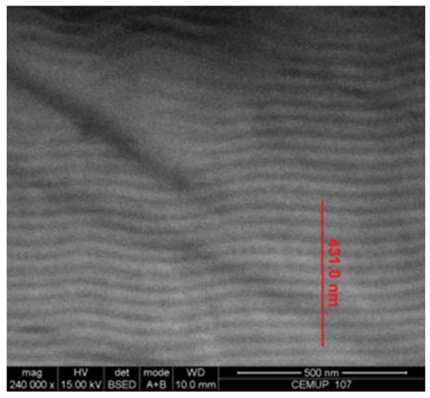
Metals 2020, 10, 170                                                                            4 of 28

applications that were chosen, while investigating the properties of the produced coatings. Studies
such as these highlight the necessity of good planning when choosing the right coating for the right
application. Furthermore, some parameters, such as coating properties (i.e., chemical composition,
hardness or coating design), influence tool performance when applied to different machining
processes (for example, roughing or finishing), but the deposition method also influences the cutting
behavior of these coatings. CVD coatings are usually applied to cemented carbide cutting tools due
to the good behavior of these materials under elevated temperatures, whereas, due to the overall low
temperature of the PVD process, this also means that this method can be used to coat tool steel, with
some studies having been done on the preparation and evaluation of these coatings [22]. However,
there are some studies that propose an approach to solve the problem of diamond deposition on steel
substrates using the CVD process. The authors propose a Ni/Cu/Ti interlayer for the diamond coating
to adhere. The coating showed good adhesion to the multi‐metal interlayer, and good wear resistance
[23,24]. The study by Silva et al. [25] evaluates the wear resistance of Ti–Al–Si–N coatings deposited
by PVD on a steel substrate; the coating was evaluated, including the adhesion of the coating, and
the authors reported that a good adhesion of the coating to the tool steel was achieved. PVD, being a
line‐of‐sight process, has some disadvantages, for example, it is harder to apply PVD coatings on
complex geometries, although this can be achieved by using, for example, pulsed high‐power
sputtering [26]. Another disadvantage of PVD is that the coating thickness is harder to control
throughout the substrate surface, however, using the mentioned pulsed high‐power sputtering, the
thickness distribution of the PVD films is more homogenous [26]. PVD coatings are usually thinner
than CVD coatings. A thin PVD coating is more suited for finishing operations, as the thinner PVD
coatings, confer the tool with a sharp cutting edge (when compared to thicker CVD coatings), also,
the compressive stresses exhibited by PVD coatings (CVD coatings exhibit tensile stresses, contrary
to the PVD coatings) are favorable; these stresses, coupled with the small layer thickness, make for a
stronger and sharper cutting edge, making these coatings ideal for finishing operations [27–29]. Still
regarding coating thickness, although generally PVD coatings are thinner than CVD coatings, there
is a novel method that enables the deposition of thick PVD coatings, using a state of the art arc‐
evaporated PVD technique, that can grow coatings up to 24.5 μm [30].
     As previously stated, coatings provide tools with properties that best fit machining applications,
and, as in the case of gradient cemented carbide tools, that have different layers with different
properties; coatings can use the same principle as these tools. This means that a coated tool may have
a multi‐layered coating, in which, for example, the outer layer has elevated wear resistance and the
subsequent layer has a main thermal dissipation function. This versatility makes coated tools very
appealing.
     Tool coatings are classified by their architecture type (number of layers/layer arrangement) and
by their chemical composition (layer composition). They are also characterized by their mechanical
properties, such as hardness, indentation modulus and their stress state (stresses induced during the
deposition of these coatings). Additionally, the microstructures of these coatings are often analyzed,
as these are linked to the mechanical properties of the coatings. There is recent research that studies
the altering of the microstructures of some coatings, in order to improve their performance.
     Coatings can have various designs, from single layer to multi‐layered coating. The types of
coating architecture are as follows:
     (a) Single layer coating;
     (b) Double layer coating;
     (c) Gradient coating;
     (d) Multilayer coating;
     (e) Nanolayered coating;
     (f) Nanocomposite coating.
     Different coatings with different designs have different types of architecture; the coating can
have, for example, a multilayered architecture. The architecture of the coating is linked to coating
design, meaning different architectures are chosen to deal with different problems.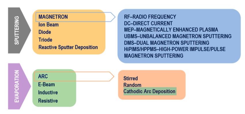
Metals 2020, 10, 170                                                                                  5 of 28

     Multilayer coating is a type of coating that shows more application in the industry by combining
more than one appealing characteristic of each layer of coating. The higher number of layers also
contributes to a hardness increase and to a higher crack propagation resistance. In this way, the tool
performance can be enhanced, making this type of coating very attractive [14,18,30,31]. Additionally,
in a study carried out by Kainz [32], multilayered CVD coating (TiN/TiBN) is compared to single‐
layered TiN and TiBN, concluding that performance is better with the multilayered coating.
     Figure 2 shows, in a scheme, how the different types of coating look when applied on the
substrate.

      Figure 2. Different designs of hard coatings. Reproduced from [14], with permission from Elsevier,
      2017.

      Coatings are also characterized by their chemical composition, for example, different types of
coatings with different chemical compositions are obtained through different deposition processes.
The most common coatings obtained by PVD processes are TiN, Ti(C, N), (Ti, Al)N, while the most
common coatings obtained by CVD are Ti(C, N), Al₂O₃, and TiN. Notice that these coatings are
employed in different types of architecture, in order to obtain a better‐suited cutting tool for a certain
machining operation [27]. It is important to note that the chemical composition is important, as
different chemical compositions have different hardnesses, friction coefficients and different thermal
conductivities, which directly influences coating wear patterns. Regarding coating microstructure, it
varies with the coating’s chemical composition. Images will be presented regarding the
microstructure of various coatings, especially those that have recently been researched. There are
various studies regarding coating microstructure, either analyzing coatings obtained by a novel
process or analyzing microstructural changes that might occur after machining. In a study by Longt
et al. [33], the cutting performance of TiAlN‐ and CrAlN‐coated silicon nitride inserts is analyzed in
the dry turning of cast iron (Figure 3). The microstructure of these coatings is also analyzed and is
displayed in the following images.
      The mentioned coatings were obtained by PVD cathodic arc evaporation, and their thickness
were about 4 μm for the TiAlN coating and about 2 μm for the CrAlN coating.

      Figure 3. (a) TiAlN coating microstructure (b) CrAlN coating microstructure. Reproduced from [33],
      with permission from Elsevier, 2014.

    The authors reported that the TiAlN coating had a dense and smooth structure with small grains,
while the CrAlN coating’s structure had formed columnar crystallites.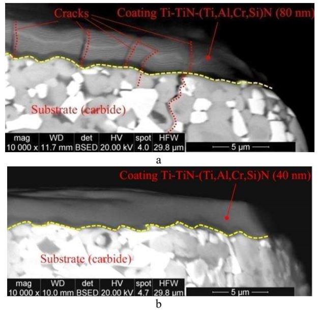
Metals 2020, 10, 170                                                                                 6 of 28

     Still regarding coating microstructure, another study [34] analyzes the influence of Ni on the
microstructure of a PVD cathodic arc evaporation obtained using AlTiN coating (Figure 4). The
cutting performance is also analyzed in this study. Three samples were analyzed, one coating
composed of AlTiN, another with 1.5% Ni and the third one with 3% Ni content. The following
images are of the microstructures of these coatings.

      Figure 4. (a) AlTiN coating microstructure with 0% Ni; (b) AlTiN coating microstructure with 1,5%
      Ni (c) AlTiN coating microstructure with 3% Ni. Reproduced from [34], with permission from
      Elsevier, 2019.

     Notice the microstructural change that is occurring: while the coating with 0% Ni (a) exhibits a
columnar microstructure, the addition of Ni promotes a more compact nanocrystalline structure.
Although the nanohardness and elastic modulus for the AlTiN coatings had the highest values (26.2
GPa and 315.8 GPa respectively), the authors report that the coating with 1.5% Ni (b) has the best
cutting performance. The lowest hardness values and elastic modulus came from the coating with
3% Ni (c) (20.9 GPa and 300.5 GPa respectively). It was also reported that the coating adhesion was
worst for the 3% Ni (c) coating, while the 1.5% Ni (b) coating was practically tied with the AlTiN
coating in terms of adhesive strength. However, the 1.5% Ni (b) coating was the coating with the
greatest toughness, improving tool life by 160%.
     Regarding multilayered coatings, these are very appellative to the machining industry, as they
confer tools with various properties that can be combined in order to achieve a satisfactory machining
process. The trend seems to be reducing layers’ thickness, in order to achieve a greater combination
of various properties, such as high hardness, a low friction coefficient, thermal conductivity, diffusion
barrier and corrosion resistance [35]. Figure 5 shows the overall structure of multilayered coatings.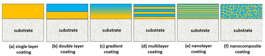
Metals 2020, 10, 170                                                                                 7 of 28

      Figure 5. Example of a complex CVD‐obtained multilayer coating microstructure. Reproduced from
      [35], with permission from John Wiley and Sons, 1969.

     The nanolayered coatings are a type of multilayered coating, the difference being the layer
thickness, which is in the nanometer range. Figure 6 shows the structure of a nanolayer TiB₂ coating.

      Figure 6. TiB2 nanolayer coating structure. Reproduced from [35], with permission from John Wiley
      and Sons, 1969.

     The coating’s structure influences the overall coating strength and adhesion to the substrate. It
is an important aspect of fabricating new coatings or finding the correct application to a certain
coating.
     As previously mentioned, the coatings are also characterized by their mechanical properties,
such as hardness, indentation modulus and the stress state of the coated tool (residual stresses that
were induced during the deposition process). These mechanical properties can be altered by changing
the coating’s microstructure, as seen in the previous study [34], or by changing the coating’s
architecture or structure. As previously mentioned, a multilayered coating has more compressive
stresses (e.g., a thin PVD coating); this will make for a stronger and more tough cutting edge.
Additionally, their high number of interfaces confers coating strength. However, these residual
stresses may provoke coating adhesion problems. In a study by Dai et al. [36], the properties of
TiB₂/Cr multilayered coatings with double periodical structures are studied. Various multilayered
architectural structures were studied, changing the thickness of the Cr layer in order to see the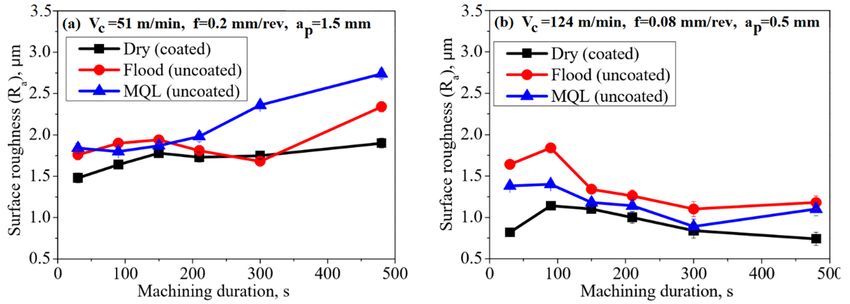
Metals 2020, 10, 170                                                                              8 of 28

changes to the microstructure and mechanical properties. It was reported that this double periodical
multilayer structure can refine the growth structure of the TiB₂ grains, resulting in a betterment of
the coating’s mechanical properties. The authors also reported that the residual stresses can be
decreased through the deformation of the metallic Cr layers, which, in turn, causes a dramatical
improvement to the coating adhesion. Additionally, keeping these residual stresses low can also
boost the peel resistance of the coatings [37].
      Coatings are applied depending on the machining process and based on the process’s pre‐
requisites, since their performance is heavily tied to the coating’s properties (chemical composition,
architecture, microstructure and mechanical properties). Because of this, coating design is very
important [21,38]. To know which coating to apply and where to apply it, studies have been
conducted to evaluate cutting tool behavior. There are many parameters able to affect the cutting
performance of a tool, such as cutting speed, feed, depth of cut and lubrication regimen, and tool
performance issues which affect the tool’s life and the overall finish quality of the workpiece. Cutting
tool behavior knowledge has proven to be key in optimizing the turning process. By changing these
parameters accordingly, a process can be optimized to meet the expected results [39], such as in the
study performed by Krishnan [40], which used the Taguchi method to predict the best parameters to
attain the lowest surface roughness when turning IS2062 E250 Steel. The parameters that were varied
(input parameters) were the cutting speed, depth of cut and feed rate. The Taguchi loss function was
used to compare the experimental values to the desired ones and to predict the output results (surface
roughness and material removal rate (MRR)). An analysis of variance (ANOVA) method was used
to determine the parameters that most influenced the desired result or the output parameters, in this
case the surface roughness and MRR. The process could then be optimized to achieve the good
surface roughness that was desired. Similarly, a study conducted by Durga [41], used the Taguchi
method to predict the best machining parameters for turning AISI 304 stainless steel with a TiAlN
nano‐coated tool. The variable parameters of this study were the cutting speed, depth of cut and feed
rate, then the authors developed regression equations based on the results for the surface roughness
and material removal rate obtained from the empirical tests to develop equations to determine the
surface roughness and material removal rate when using coated or uncoated tools for this type of
experiment. Recently, studies on the parameters that influence tool performance are focusing on the
minimum quantity lubricant (MQL), studying the effect of using this method in the machining of
various materials using different tools. The study performed by Khan and Maity [42], which employs
MQL using vegetable oil and compares it to dry cutting and flood cooling when turning commercially
pure titanium, obtained satisfactory results, reducing cutting forces and cutting temperature when
using this approach. Tool geometry also affects the cutting performance, because, by analyzing the
cutting tool behavior more adequately, geometries can be created to achieve the desired results.
Regarding the study carried out by Harisha et al. [43], cutting tool geometry is analyzed in order to
minimize the cutting force when turning hardened steels, this is because tool geometry, when
incorrect, leads to energy loss which results in loss of productivity.
      In this paper, the recent advances in coated turning tool behavior are analyzed, looking at the
different coatings that have been used in recent years. The different wear mechanisms which the
coated turning tools are subjected are also going to be analyzed and presented, relating the different
wear mechanisms to the coated tool life. There is also a chapter in this paper that will be reserved to
the behavior of coated tools under advanced lubrication or cutting conditions, such as, turning using
MQL conditions or using cryogenic conditions. Finally, the paper will conclude with a summary of
each chapter and there will be mention of what are the recent trends in the turning process using
coated tools.

2. Coatings for Turning Tools
     In coatings applied to tools, or hard coatings, generally, nitrides, carbides, borides and oxides of
transition metals are used. The nitrides used as coatings for cutting tools are TiN, TiAlN, CrN, ZrN,
TiSiN, TiAlSiN, CrAlN, TiAlCrN, and cBN [8,9,14,41]; carbides for coatings are TiC, CrC, and WC.
For boride coatings, TiB₂ is used due to its chemical inertness, high hardness and good wear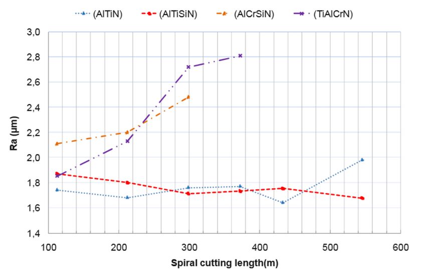
Metals 2020, 10, 170                                                                                 9 of 28

resistance. Additionally, they can be deposited in tool steel with good adhesive capabilities [44,45].
One of the most widely used oxide coatings is the Al₂O₃. Other somewhat common coatings for
cutting tools are DLC, MoS₂ and WC‐C [13,15].
      Due to the drastic tool life reduction, and overall unsatisfactory surface roughness values of the
workpiece when using high speed steel (HSS) as a tool material, the industry has been using tool
coatings to overcome the issues arising from the use of HSS. In a study by Gupta et al. [46], the cutting
characteristics of PVD‐coated turning tools were analyzed. The test involved the turning of C45 steel
using solid tools coated with TiN, AlCrN and TiAlN. Cutting forces were measured, while cutting
speed and feed rate were varied throughout the testing process. The TiAlN coating proved to be the
most efficient, relative to tool life, due to its hardness and self‐lubricating ability, almost avoiding the
adhesion of the workpiece material to the tool surface, and therefore increasing tool life. Research
like this continues to be important, as the choice of the right coating can prove to be a profitable choice
for manufacturers, a fact that explains the vast amount of studies performed in this area, from finding
optimal conditions to machine a certain material, to comparing various types of coatings with
different structures or coating methods. In the following paragraphs, recent studies made on the
comparison of various coatings, and studies that use coated tools with novel/complex geometries in
the turning process, are going to be presented.
      The work developed by Koyilada [47], testing the machinability characteristics of Nimonic C‐
263, used coated cemented carbide for turning that material under dry machining conditions.
Carbides were coated with commercially available CVD bilayer coating (TiCN (bottom layer)/Al₂O₃
(top layer)), and PVD multilayer coating (TiAlN/TiN), consisting of alternating layers of TiN and
TiAlN on the substrate. Both these coating types were compared. The results show that the PVD
coating presented a remarkable improvement in the surface finish of the workpiece when compared
to the CVD‐coated tool. Cutting forces measured in the tests were also lower when the PVD coating
was in use. Additionally, the PVD coating outperformed the CVD bilayer coating in terms of tool life.
This is due to the PVD‐coated tool presenting a superior compressive strength when compared to the
CVD‐coated tool (due to deposition technique and multilayer configuration), making it more suitable
to work under a fluctuating load. Due to the microstructure of Nimonic C‐263, the tool is subjected
to dynamic fatigue, even in continuous machining, which explains the underperformance of the CVD
coating in this case. Although the PVD multilayer coating is preferred for higher cutting speeds,
ranging from 50–90 m/min (further cutting speed augmentation would require the use of a cutting
fluid paired with the coated cutting tools), the CVD bilayer coating should be used to turn this
material at speeds below 60 m/min, because the top layer of Al₂O₃ has a low thermal conductivity,
which results in a higher machining temperature at higher cutting speeds. This eventually leads to
wear problems, especially material adhesion and coating disaggregation.
      Another study that compares the characteristics of CVD and PVD‐coated carbide tools, is a work
presented by Ginting [48] which studies the productivity of AISI 4340 hard turning using
multilayered CVD (TiN (top layer)/Al₂O₃/TiCN (bottom layer)) and monolayered PVD coatings
(TiCN). Productivity was characterized by the material removal rate (MRR) and volume of material
removal (VMR). Otherwise, the variables analyzed in the tests were cutting speed, feed rate and
depth of cut. The upper limits set to the coated tools reveal that the CVD multilayer‐coated carbide
can achieve a slightly higher feed rate and depth of cut value. In terms of tool life, the PVD monolayer
coated tool endured for longer than the CVD‐coated tool. In terms of surface roughness, the PVD
coating was more effective as well. As mentioned above, PVD coatings have more sharp edges and
are thinner, providing a better quality surface finish, however, in terms of productivity the CVD‐
coated carbide achieved values higher by about 78–125% than the monolayer PVD‐coated tool. This
highlights the fact that choosing the right coating method and type of coating can prove an
advantage. As seen in that study, the PVD‐coated tool performs better regarding tool life and overall
surface finish quality, but in terms of MRR the CVD‐coated tool is more effective. This is due to the
coating properties: while the PVD coating (TiCN) is harder than the outer layer of the CVD coating
(TiN), its friction coefficient is also lower when compared to the TiN. This, coupled with the fact that
thin PVD coatings confer the tool with sharper cutting edges and have more compressive stresses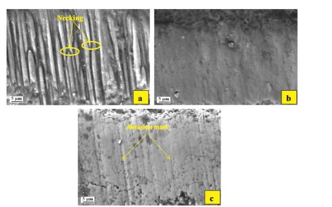
Metals 2020, 10, 170 10 of 28
(caused during the PVD process [29]), give the PVD coating superior finishing capabilities when
compared to this CVD coating.
In the work presented by Kumar et al. [49], the performances of PVD coated carbides using
TiAlN, AlCrN and TiAlN (top layer)/AlCrN (bottom layer) were tested in the turning of Inconel 825,
as well as uncoated carbide tools. The performance of each tool was evaluated, taking into
consideration the flank wear of the tool, work‐piece surface roughness, cutting force generated
during the cutting process and chip formation. The optimal machining parameters were analyzed
using grey relational analysis under multiple response optimization, and the results showed that the
bilayer coating (TiAlN/AlCrN) outperformed the single layered coatings, TiAlN and AlCrN, in the
machining of this alloy.
Still regarding the comparison between CVD‐ and PVD‐coated tools, the study performed by
Koseki et al. [50] compares TiN‐coated tools obtained by different deposition methods in the
continuous turning of Ni‐based super‐alloys. These high‐strength, low‐conducting alloys require
higher cutting forces and temperatures than other materials during the machining process. The
damage suffered during the tests was investigated, and the CVD coating proved to be more efficient
in the machining of these alloys, suffering almost no change in coating hardness and overall less
plastic deformation in the process.
A method that has seen some use is the coating of a textured tool in order to promote better chip
removal, better adhesion of the coating to the tool and even an improved tool life. In the work
developed by Mishra [51], the machining performance of laser‐textured chevron shaped tools, and
untextured tools was evaluated. These tools were coated with AlTiN and AlCrN using PVD. Cutting
forces and tool wear were analyzed for textured and untextured cutting tools. Coating growth on
textured tools was better, presenting a reduced number of microcavities and macroparticles for both
coatings. The value of the cutting forces was lower for the textured tools, resulting in less tool wear,
and the texture on the tools improved the tool‐coating adhesion. The chips formed by the textured
tools were thinner when compared to untextured tools, however, chip fragments were embedded in
the textures. Thus, machining parameters need to be adjusted in order to find a balance between these
two phenomena in order to produce favorable machining conditions.
As previously stated in Chapter 1, discussing developments in gradient cemented carbide tools,
studies on the influence of this gradient and on how to control the grain size of the cemented carbide,
have been conducted [11,12]. These gradient cemented carbides already represent a significant
improvement when using uncoated cemented carbide tools. Additionally, these gradient cemented
carbides may improve the quality of the coating, making it more adherent to the substrate, and even
improve tool performance. A paper presented a study regarding CVD coating application on gradient
cemented carbide tools of different grain sizes, where it was observed that the coating thickness is
related to the carbide grain size, coating thickness increases with smaller grain sizes [52]. It was also
concluded that the adhesion strength of the coating is overall better on gradient cemented carbides
when compared to regular cemented carbides, however, the adhesion strength drops when the grains
of the cemented carbide are finer. A thicker coating may not be ideal for finishing operations,
however, for roughing operations, having a thicker coating may be beneficial.
Cutting tool coatings may also provide a sustainable eco‐friendlier alternative when machining
certain materials, as some of these materials, for example, nickel‐based super‐alloys, already
mentioned in this chapter, require higher cutting speeds, which results in higher cutting forces and a
higher temperature in the cutting area. To counteract these problems, lubrication is employed,
sometimes by flooding the cutting area. Practices like these have proven to be unsustainable and
damaging to the environment.
A recent tendency is to employ methods able to reduce the high usage of these lubricants and
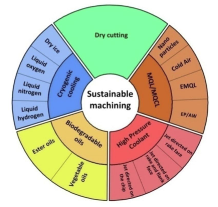
make the overall machining process more eco‐oriented. These methods (Figure 7) sometimes use
biodegradable oils, such as vegetable oils, as lubricants. Dry machining is also a sustainable option,
as it removes the use of cooling fluid altogether, having as its alternative the minimum quantity
lubrication (MQL) method, in which small amounts of lubricant are employed. MQL presents itself
as being a viable alternative to dry machining when having problems with cutting temperature orMetals 2020, 10, 170 11 of 28
surface finish quality. Other sustainable methods, such as cryogenic cooling, or the use of a high‐
pressure coolant, in which the coolant is applied to a select area of the tool, are employed as an
alternative to the conventional flood cooling method [53].
Figure 7. Wheel of sustainable machining. Reproduced from [53], with permission from Elsevier,
2019.
The work produced by Thakur and Gangopadhyay [54] proposes a sustainable alternative to the
machining of nickel‐based super alloy, by employing TiN/TiAlN PVD‐coated tools and dry turning
of the Incoloy 825. Tests were conducted employing different lubrication methods, such as dry
machining, flood machining and MQL. Cutting forces, temperature of the cutting area, tool wear and
surface integrity were evaluated. While the temperature in the cutting area was higher for dry
machining when using a PVD‐coated tool, the overall surface finish was of better quality when
compared to flood cooling and MQL. Moreover, cutting forces also presented lower values when
using a PVD coating, even in dry machining. This means that the cutting force necessary would be
lower, therefore promoting a more environment‐friendly alternative (dry machining); an overall
better surface finish was obtained using the PVD‐coated tool under an MQL environment.
Regarding nanolayered coatings, they are quite appealing, mainly due to their high hardness
value, for example, research was done on nanolayer TiN/VN coatings, and results found that there
was a very high hardness increment [55]. This hardness increase is related to the nanolayer thickness,
as see in Figure 8.Metals 2020, 10, 170 12 of 28
Figure 8. Hardness increase of a TiN/VN coating, over the thickness of the bilayer. Reproduced from
[14], with permission from Elsevier, 2017.
The reason for this hardness increase was attributed to the large number of interfaces between
layers, characteristic of nanolayered coatings. In Figure 9, the structure of a CrN/TiAlN nanolayered
coating deposited on steel is shown [14].
Figure 9. CrN/TiAlN nanolayered coating structure. Reproduced from [14], with permission from
Elsevier, 2017.
The structure shown in Figure 9, characteristic of nanolayered coatings, confers the coatings a
very high crack propagation resistance, as the cracks tend to not propagate as deep as in a
monolayered coating, thus risking damage to the substrate. These coatings are very similar to the
multilayered coatings, the main difference being the thickness of each layer and that the hardness
value for a nanolayered coating is not equal to the average hardness of its constituents—however,
this is the case for regular multilayered coatings [14]. A recent study about the influence of the
thickness of these nanolayers in coatings found that, for hardness values at room temperature, there
were no significant changes between the coatings with differing thickness layers. However, the
cutting properties of the coatings were different, with the coating with the thinnest nanolayers
exhibiting a higher tool life than the coating with thicker nanolayers [56].
As mentioned previously, understanding cutting tool behavior is the key to correctly optimizing
a machining process. There are many studies on coatings’ behavior while cutting, for example, in the
study presented by Gassner et al. [57], the thermal crack network on CVD TiCN/Al₂O₃‐coatedMetals 2020, 10, 170 13 of 28
cemented carbide cutting tools is analyzed. The theme of coating tools and coating performance is
heavily researched, comparing coating methods to achieve overall better machining results, or even
finding an eco‐friendlier alternative to machining certain materials.
3. Coating Influence on Turned Surface Quality
There are many factors that influence surface quality in the turning process, as seen in Chapter
1. A turning process can be optimized in order to have the best possible surface quality, by changing
certain parameters, such as rotation speed, feed rate and depth of cut. These parameters are mainly
dependent on the machine, as the machine also influences cutting performance and the overall
surface finish of the machined piece [58]. There have been studies that relate the chip formation
thickness to the overall surface roughness of the machined piece [59]. Using a prediction method to
determine chip formation thickness can serve as a monitor of the surface roughness of certain
materials. However, there are more factors that influence the surface roughness of turned pieces, such
as lubrication method and tool geometry, and the coating that is being employed also affects the
overall surface quality of the workpiece. As previously mentioned, thin PVD coatings are very well
suited to surface finish operations, and provide an overall better surface quality than thicker coatings.
This is mainly due to the sharp edges that are conferred to the substrate, and compressive stresses
that confer the tool edge strength [27–29].
In this chapter, the influence of coated tools on the surface quality of various materials are
presented. The materials selected are mainly titanium alloys and nickel‐based super‐alloys, as these
are very appealing for structural and engineering applications, especially due to their strength‐to‐
weight ratio. Although these alloys have some processing problems associated with them, for
example low machinability rating, their poor machinability may be attributed to material properties,
such as high hardness at high temperatures, low thermal conductivity and high chemical reactivity
[60]. There have been some studies conducted on the turning of hardened steels, which will also be
presented in this chapter, highlighting the coating’s influence on turned surface quality.
In the aforementioned study [40], a comparison of the machining performance of coated tools,
using a monolayer PVD coating TiCN and a multilayer CVD coating TiN/Al₂O₃ in the hard turning
of AISI 4340 steel. The authors found that, in this case (and as elaborated above), the PVD coating
would be best suited for finishing operations, especially due to the hardness values of TiCN and the
lower friction coefficient (when compared to the TiN top layer of the CVD coating). The surface
roughness values obtained for the PVD‐coated carbide and for the CVD‐coated tool, are (0.8–1.6)
micron and (1.6–3.2) micron, respectively. However, for material removal rate the CVD coating is
preferred, although the turned surface quality is poorer than those using PVD coatings.
The study by Fernández‐Abia et al. [28], presents a comparison of four coatings (and an uncoated
tool) in the turning of austenitic stainless steel, AISI 304L. The cutting behavior of these coated tools
were analyzed. The authors mention that these types of PVD coatings are best suited for achieving
low values of surface roughness, especially due to the sharp edges conferred by the PVD process. The
coatings used were, AlTiN; AlTiSiN; AlCrSiN; and, finally, TiAlCrN. The first three coatings are
nano‐structured coatings. The graph of Figure 10 shows the results obtained from this study,
regarding the surface roughness of the machined material.Metals 2020, 10, 170 14 of 28
Figure 10. Graphic of surface roughness value (Ra) for different PVD coatings [28].
The best coatings for the machining of this material are the AlTiN and AlTiSiN coatings; this is
due to their nano‐crystalline structure. Although AlCrSiN also has this beneficial nanostructure, the
presence of chromium in its chemical composition favors the creation of an oxide protective layer
that is inferior to the AlTiN and AlTiSiN coatings.
Regarding the turning of nickel‐based super‐alloys, in this study [54], the influence of coating
and lubrication/cooling method was observed in the turning performance of Incoloy 825, using a
TiN/TiAlN multilayer coating. The results regarding surface roughness obtained from these tests can
be interpreted from the graphs in Figure 11.
Figure 11. Different values of surface roughness for the machining duration. (a) and (b) have different
cutting parameters. Reproduced from [54], with permission from Elsevier, 2016.
The coated tool provides the better surface roughness quality from the tests that were carried
out. The fact that dry machining with coated tools provides a better surface quality is quite an
interesting finding, as this type of machining is sustainable and eco‐friendly, and these coatings
enable the machining of high‐quality parts at a lower price/environmental impact. The authors also
added that the cutting temperature was lower for the dry machining using PVD TiN/TiAlN‐coated
tools. A study was also mentioned before [49], in which a PVD and CVD coating were used in the
machining of Nimonic C‐263; the findings of these authors report that the PVD TiN/TiAlN
multilayered coated tool is better for the surface finish. Due to the sharper edges, this coating
provided a 14.3% reduction in surface roughness value when compared to the CVD TiCN/Al₂O₃Metals 2020, 10, 170 15 of 28
counterpart, in which a higher edge radius contributed to the lower turned surface quality. As stated
previously, the PVD coating is preferred for higher machining speeds than the CVD coating.
Without a doubt, coatings improve the overall surface finish quality of turned parts, however,
tools with the correct geometry can rival the low roughness values obtained, especially those with
thinner PVD coatings. By analyzing the literature, a trend can be seen, with thin PVD coatings usually
being employed in finishing operations, explained by the residual stresses that thin PVD coatings
have (compressive stresses), and by the sharp cutting edge that these coatings confer to tools. Their
chemical composition is also a contributing factor, as, depending on the coating chemical
composition, these will react differently with the material that is being turned, sometimes even
forming hard protective layers that lower the friction coefficient, thus improving overall coated tool
performance [25].
4. Tool Wear Mechanisms
Coated cutting tools significantly improved the tool life of conventional tools, as coated tools
suffer overall less wear in the same lifetime as an uncoated one, particularly at high machining speeds
[61], however, coated tools eventually give out, due to the fact that a lot of these coated tools are used
in dry machining conditions, which means that the machining temperature is overall higher. A coated
tool has different wear mechanisms, such as abrasive wear, thermal cracks, adhesive wear, build up
edge (BUE), or coating structure failure, resulting in spalling or cracks appearing on the coating.
Understanding the different wear mechanisms for each coating type helps one make a better coating
or machining parameters choice to achieve the desired results. These wear mechanisms are related to
some parameters; for example, when there is an increase in the cutting force, it can be assumed that
the coating is suffering abrasive wear, or that there is a problem with the coated tool’s edge. Wear is
also related to the coating properties, different coatings (or coating layers) have different hardnesses,
friction coefficients and thermal conductivities, all factors that also contribute to the wear patterns of
these coated tools. Coating microstructures can influence factors, such as coating adhesion, that might
cause fracture wear later. Mechanical properties, such as hardness, indentation modulus and the
stress state of the coating itself, affect the wear patterns that these will suffer. In some cases, high
residual stresses can cause problems with coating adhesion, that is, the coating’s adhesive strength is
lower, and the coating is more likely to suffer spalling or delamination, although, as mentioned
before, different coatings obtained by different deposition methods have different stress states.
Hardness is primarily tied with abrasive wear, as well as the coefficient of friction (COF); the latter
being related to coating design (layer thickness or layer chemical composition), as seen in the study
by Dai et al. [36], where it is reported that the increase in the thickness of a Cr layer, in a multilayered
TiB₂/Cr coating with double periodical structures, would result in a decrease in coating hardness and
an increase in coefficient of friction, which will affect the coated tool’s wear rate.
In this chapter, some studies regarding different wear mechanisms and coating degradation will
be addressed, presenting images for some types of wear mechanisms, as well as a summary of the
findings of these studies.
In a work mentioned in the previous chapter [50], there is a study on the wear of TiN coatings
obtained by different deposition methods. In addition to abrasive wear and fracture wear, a common
wear mechanism is adhesive wear, where the material adheres to the coated tool. In Figure 12, the
wear mechanisms for the TiN coating, obtained by different deposition methods, can be seen on the
tool’s cutting edge.Metals 2020, 10, 170 16 of 28
Figure 12. Wear mechanisms on TiN coating, in the continuous turning of a nickel‐based super‐alloy
using different coating techniques: (a) PVD‐arc, (b) PVD‐SP, (c) PVD‐HCD and (d) CVD. Reproduced
from [50], with permission from Elsevier, 2015.
In Figure 12, in addition to noticing the adhesive material on the cutting edge, other wear
mechanisms can be seen, such as fracture wear, where the cemented carbide substrate is exposed.
There is also micro‐abrasion wear that can be noted on all the samples.
Still regarding the same study [60], some plastic deformation can be observed in the coating
(Figure 13). In this image, a broken coating area and adhesive material can also be seen.
Figure 13. High resolution TEM image regarding a TiN coating obtained by PVD‐Arc, noticing wear
on the surface of the tool. Reproduced from [50], with permission from Elsevier, 2015.
Also due to temperature, thermal cracking may occur on the coating. Another study regarding
thermal cracking of CVD TiCN/Al₂O₃‐coated cemented carbides [57] analyzes various methods to
close the cracks that occur due to excessive cutting temperature, such as wet blasting or filling the
cracks with TiO₂. This wear mechanism can be observed in Figure 14, taken from the same work.Metals 2020, 10, 170 17 of 28
(a) (b)
Figure 14. (a) SEM image of rake face of a coated CVD insert after face turning (b) highlighted section
of the rake face. Reproduced from [57], with permission from Elsevier, 2019.
Regarding crack defects on cutting tools, the study performed by Vereschaka et al. [56]
highlights the influence of the PVD Ti‐TiN‐(Ti,Al,Cr,Si,)N nanolayer coating thickness, which was
tested in the turning of AISI 321 steel. The coatings differed in the number of nanolayers and
nanolayer thickness; the coating with the ticker nanolayers had a total of 33 nanolayers (Coating A),
and the other coating, with the thinner nanolayers, had a total of 57 of these layers (Coating B). These
coatings were also tested against monolayered Ti‐(Ti,Al)N‐coated and uncoated tools, and both the
nanolayered coatings presented a higher tool life than these last two. However, Coating A has less
wear resistance and, with the increase in cutting speed, the cutting temperature also increased,
inducing thermal stresses in the superficial layers of the tool. This can be observed in Figure 15, where
(a) is the image regarding the thickest nanolayered coating and (b) is the thinnest one. The thinner
layers provide the coating with a higher wear resistance, which means that thinner layers better resist
thermal stress crack formations.
Figure 15. Crack formation on PVD nanolayered coating surface, area directly adjacent to the cutting
edge; (a) coating with nanolayers of 80 nm and (b) coating with 40 nm nanolayer thickness [56].
Coatings, when deposited, mirror the substrate surface, resulting sometimes in an uneven
coating surface, with imperfections such as cracks, and even residual stresses that may have resulted
from the coating process. These superficial imperfections may cause material transfer and have a
negative impact on the coated tool performance, by promoting tool wear or by not conferring theMetals 2020, 10, 170 18 of 28
desired surface finish. Some methods have been proposed to minimize these defects, such as a post‐
deposition polishing of the coated tool, in order to lower its overall surface roughness and minimize
the potential for material transfer [62]. Another method proposed to deal with cracks is shown in the
paper presented by Faksa et al. [63], where the authors study the effect of shot peening on residual
stresses and crack closure in CVD‐coated hard metal cutting inserts. Due to the stresses seen on the
deposition process of the CVD coating on hard metal, the surface layer of the coating exhibits cracks.
The authors conclude that well placed and calculated shots can close these cracks and prevent crack
nucleation and growth in CVD coatings. These residual stresses also have an influence on PVD films,
as shown by Skordaris et al. [64], who studied the effects of PVD films’ residual stresses on their
mechanical properties, brittleness, adhesion and cutting performance. The coatings used are PVD
TiAlN, and different coatings were used, these having different levels of residual stress, obtained by
heat treatment. The authors concluded that there is a significant contribution of the film’s
compressive stresses to increasing the mechanical properties of the coating and adhesion,
consequently improving tool life.
The wear mechanisms of a MTCVD–TiCN–Al₂O₃‐coated cemented tool was also analyzed in
another study [65], where wear patterns were observed after 142 min of turning 300 M steel, at a
cutting speed of 300 m/min. Crater spalling could be observed, as well as evidence of molten metal
particles, which means that the cutting temperature was very high. Signs of adhesion, matrix
exposure and build up layer (BUL) were also observed. These wear patterns can be observed in Figure
16.
Figure 16. Different wear patterns on the MTCVD coating after 142 min of turning 300 M steel. The
rake face (a) was analyzed in two regions A (depicted in (b) presenting signs of cooling molten
metal), and region B (depicted in subfigure (c), where signs of BUL and micro‐cracks can be noticed).
In subfigure (d) the flank face is displayed, and zones C and D are analyzed. Zone C is displayed in
subfigure (e), where adhesion damage can be noted, and some grooves. Lastly, zone D is displayed
in (f), where adhesion damage is the predominant type of wear mechanism. Reproduced from [65],
with permission from Elsevier, 2017.Metals 2020, 10, 170 19 of 28
An analogous study [66] using similar conditions (maintaining the same coating and machined
material) was conducted in order to analyze the main wear mechanisms of the coated tool. The wear
patterns are like those observed in the previous study [65]: adhesive wear, build‐up layer (BUL),
molten material and crack wear patterns were detected in the coated tool. The authors conclude that
the main wear mechanisms are adhesive wear, abrasive wear, oxidation wear and diffusion wear.
During the tests, cutting parameters were varied, such as cutting speed and feed rate. Cutting forces
were also analyzed, because this is an important step when optimizing a process.
In another work [67], the wear mechanism of PVD‐, CrAlN‐ and TiAlN‐coated Si₃N₄ ceramic
cutting tools was studied. The conducted tests consisted of the turning of GT250 gray cast iron using
these coated tools and characterizing the wear mechanisms. It was found that the adhesive strength
of the TiAlN was stronger than the CrAlN coating; during the turning of the material, the CrAlN
coating suffered spalling at a cutting speed of 400 m/min, due to low adhesive strength. During the
dry turning of the material, abrasive wear and minor adhesive wear were found to be the main wear
mechanisms. It was possible to observe that coated tools suffered more adhesive wear than the
uncoated inserts. Still regarding the coated Si₃N₄ ceramic cutting tools, studies made on the wear
mechanism of these tools coated with diamond were conducted [68,69], the authors observed the
machining performance of coated and uncoated tools; it was found that the cutting force was higher
during machining with diamond‐coated tools, due to the surface roughness of the rake face.
Additionally, the parameter that influenced these cutting forces the most was the feed rate,
contributing more to the increase in cutting force than cutting speed. Regarding wear mechanisms, it
was observed that the high machining temperature promoted the graphitization of the diamond
coating, which resulted in its removal from the tool; however, there was no delamination observed
in the coating after machining.
As previously stated, a recent shift to dry turning as an alternative to some machining methods
has been observed, due to economic and environmental reasons. Naskar et al. [70] in their
investigation, compared the flank wear mechanism of CVD and PVD hard coatings in the high‐speed
dry turning of low‐ and high‐carbon steel. The steels in question are C20 and C80, and they were
turned at a cutting speed of 300 m/min and 600 m/min with CVD Al₂O₃ (top layer)/TiC (bottom layer),
TiCN (top layer)/TiC (bottom layer) bilayer‐coated, and PVD TiAlN single‐layer‐coated, inserts. The
authors found that the main wear mechanisms were abrasive wear, however, plastic deformation‐
induced necking and dissolution‐diffusion were also contributing to the acceleration of tool wear.
They concluded that when designing a coating material for high speed machining, the solubility of
coating materials has to be taken into account.
Figure 17, taken from the paper presented by Naskar et al. [70], exhibits the wear of coated tools
(coatings presented in the above paragraph), in the machining of C80 steel.You can also read