Record FlowControl - Translation of the original manual
←
→
Page content transcription
If your browser does not render page correctly, please read the page content below
record FlowControl

                                     User manual

Translation of the original manual
Document identification Article nr.: 121-006454644 Version: 1.3 Publication date: 23/03/2021 Subject to technical modifications Copyright © agtatec ag
Table of contents

Table of contents
    Table of revision ...............................................................................................................................................        4

1 Safety.................................................................................................................................................................    5
  1.1     Presentation of warning signs...............................................................................................................                       5
  1.2     Intended purpose of use .......................................................................................................................                    5
  1.3     General hazards ...................................................................................................................................                6
  1.4     State of technology ...............................................................................................................................                8
  1.5     Personal protective equipment .............................................................................................................                        8
  1.6     Spare parts and liability ........................................................................................................................                 9

2 General information .........................................................................................................................................             10
  2.1    Purpose and use of the instructions .....................................................................................................                          10
  2.2    Copyright ..............................................................................................................................................           10
  2.3    Product identification ............................................................................................................................                10
  2.4    Manufacturer BLASI GmbH ..................................................................................................................                         10
  2.5    Target groups .......................................................................................................................................              10
  2.6    General definitions of terms..................................................................................................................                     11

3 Description........................................................................................................................................................       12
  3.1    Graphical presentation..........................................................................................................................                   12
  3.2    Overall view ..........................................................................................................................................            12
  3.3    Function ................................................................................................................................................          13
  3.4    Authorization levels...............................................................................................................................                13
  3.5    Count data analysis and data transfer (optional) ..................................................................................                                14
  3.6    Operating modes ..................................................................................................................................                 14

4 Technical data................................................................................................................................................... 15

5 Operation...........................................................................................................................................................      17
  5.1    BDE-D FC and key functions................................................................................................................                         17
  5.2    Instructional symbols ............................................................................................................................                 18
  5.3    Menu display.........................................................................................................................................              18
  5.4    Status display .......................................................................................................................................             18
  5.5    Select Permission Level .......................................................................................................................                    18
  5.6    Restart via keyboard.............................................................................................................................                  18
  5.7    Operating lock via the keyboard ..........................................................................................................                         19
  5.8    BDE-D FC Menu ...................................................................................................................................                  20
  5.9    Viewing and resetting counting statistics ..............................................................................................                           21
  5.10   Setting the door control.........................................................................................................................                  21
  5.11   Setting the LED Strips ..........................................................................................................................                  22
  5.12   Setting the Voice Box (Option) .............................................................................................................                       23

6 Servicing and maintenance ............................................................................................................................. 24
  6.1     General remarks ................................................................................................................................... 24
  6.2     Monthly inspection work to be carried out by the operating company .................................................. 25

7 Malfunctions .....................................................................................................................................................        26
  7.1      Behavior in event of faults ....................................................................................................................                 26
      7.1.1 Malfunction indication ......................................................................................................................                   26
      7.1.2 Possible troubleshooting..................................................................................................................                      26

8 Taking out of service and disposal................................................................................................................. 27
  8.1    Decommissioning ................................................................................................................................. 27
  8.2    Dismantling and disposal...................................................................................................................... 27

BAL_FlowControl_EN_1V3_REC_121-006454644                                                                                                                              3 / 28
Table of revision Table of revision B BDE-D FC Menu New chapter ........................................................................................................................................................ 20 4 / 28 BAL_FlowControl_EN_1V3_REC_121-006454644
Safety       1

1         Safety
1.1       Presentation of warning signs
          Various symbols are used in this guide for easier understanding:

           NOTICE
          Useful advice and information to ensure correct and efficient workflow of the system.

           IMPORTANT
          Specific details which are essential for trouble-free operation of the system.

           IMPORTANT
          Important details which must be read for proper function of the system.

           CAUTION
          Against a potential hazardous situation that can lead to minor personal injury and property
          damage.

           WARNING
          Against a latent hazardous situation that can lead to severe injuries or death and cause sub-
          stantial property damage.

           DANGER
          Against an imminent hazardous situation that can lead to severe injury or death.

           DANGER
          Against an imminent or latent hazardous situation that could lead to electric shock and cause
          serious injury or death.

1.2       Intended purpose of use
          The system is designed exclusively for use as a pedestrian passage. The installation may only occur
          in dry areas. If there are deviations then proper waterproofing and water drains will be required on-
          site.
          Any other application or use beyond this purpose is not considered to be an intended purpose. The
          manufacturer bears no liability for any resulting damage; the operator alone shall bear the associated
          risk.
          The intended purpose also includes observation of the operating conditions specified by the manufac-
          turer, in addition to regular care, maintenance and repair.
          Interventions in or alterations to the installation performed by non-authorized maintenance technicians
          exclude the manufacturer's liability for consequential damages.

BAL_FlowControl_EN_1V3_REC_121-006454644                                                                   5 / 28
1 Safety
1.3 General hazards
The following section lists hazards that can be caused by the system even when used as intended.
To reduce the risk of malfunction, damage to property or injury to persons and to avoid dangerous
situations, the safety instructions listed here must be observed.
The specific safety instructions in the other sections of this manual must also be observed.
IMPORTANT
The country-specific regulations must be observed and complied with!
IMPORTANT
To avoid malfunctions, moving objects such as flags or parts of plants must not be allowed to
enter the detection range of the sensors.
CAUTION
Risk of malfunctions, material damage or injury due to improper settings!
a) Improper settings can lead to malfunctions, material damage or personal injury.
ð Do not disconnect the system from the power supply overnight.
ð Settings should only be made by personnel qualified to do so.
ð Do not disassemble, put out of operation or manipulate safety devices.
ð Have faults rectified by specialist personnel or by personnel qualified to do so.
ð Have service and maintenance carried out according to locally applicable regulations or accord-
ing to a maintenance contract.
CAUTION
Risk of malfunctions, material damage or injuries due to insufficient or missing cleaning or
care!
a) Insufficient or inattentive cleaning or care of the system can lead to malfunctions, damage to
property or injury to persons.
ð Check the sensors regularly for dirt and clean them if necessary.
ð Regularly remove dirt accumulations in the floor rail or under the floor mat.
ð Keep the system free of snow and ice.
ð Do not use aggressive or caustic cleaning agents.
ð Use road salt or loose chippings only conditionally.
ð Lay the floor mat without folds and flush with the floor.
ð Equipment required for cleaning purposes such as ladders or similar must not be leaned on or at-
tached to the system.
6 / 28 BAL_FlowControl_EN_1V3_REC_121-006454644Safety 1
CAUTION
Risk of material damage or injury due to unforeseen opening, closing or turning of the door!
a) The door can open, close or turn unexpectedly. This may result in damage to property or injury
to persons.
ð No persons may be present in the opening area of the system.
ð Ensure that moving objects such as flags or parts of plants do not enter the detection range of
the sensors.
ð Do not make any settings on the control unit when the system is in use.
ð Have faults rectified immediately by specialist or personnel qualified to do so.
ð Remove objects from the opening area.
ð Do not disassemble, put out of operation or manipulate safety devices.
ð Do not rush through a closing system.
CAUTION
Risk of bruising and severing of limbs!
a) If the system moves, careless behaviour can lead to serious injuries to limbs or severance of
limbs.
ð Do not reach in when parts of the system are moving.
ð Keep a distance when parts of the system move.
ð Do not bump into or touch the system when it is moving.
ð Do not open or remove protective covers during operation.
ð Do not permanently remove covers from the system.
ð Only carry out inspection, service, maintenance and cleaning when the system is stationary and
switched off.
CAUTION
Danger of material damage or injury due to non-functioning safety devices!
a) If safety devices are not functioning, manipulated or put out of operation, there is a risk of dam-
age to property or injuries that can lead to death.
ð Never disable or manipulate safety devices.
ð Have inspection, service and maintenance of the safety devices carried out according to local
regulations or according to a maintenance contract.
CAUTION
Danger of malfunctions, damage to property or risk of injury if used by unauthorised persons!
a) If unauthorised persons use the system, there is a risk of malfunction, damage to property or in-
jury to persons.
ð Children under 8 years of age may only use the system under supervision.
ð Children must not play with or on the system or clean and maintain it.
ð Persons with limited physical, sensory or mental abilities as well as persons with insufficient
knowledge or experience may only use the system under supervision or must have received and
understood instructions to do so.
BAL_FlowControl_EN_1V3_REC_121-006454644 7 / 281 Safety
DANGER
Danger to life due to electric current!
a) In case of contact with live parts, there is an immediate danger to life due to electric shock.
Damage to or removal of the insulation or individual components can be life-threatening.
ð Before starting work on active parts of electrical systems and equipment, ensure that all poles are
voltage free and that this is maintained for the duration of the work.
ð Keep moisture away from live parts. This can lead to a short circuit.
ð Never bridge fuses or put them out of operation.
ð Do not connect the power supply until all work has been completed.
ð Have work on the electrical system performed by qualified personnel only.
DANGER
Danger to life due to non-functioning safety devices of the fire protection system!
a) If safety devices of the fire protection system do not function properly, there is a risk of serious
or fatal injuries.
ð Never disconnect the fire protection system from the power supply overnight.
ð Do not disassemble, put out of operation or manipulate safety devices.
ð Do not remove safety instructions on the system.
ð Never block, hold open or otherwise prevent fire doors from closing.
ð Have inspection, service and maintenance of the fire protection system carried out in accordance
with locally applicable regulations or according to a maintenance contract.
ð Have the fire protection system checked and maintained according to the state of the art.
1.4 State of technology
This system was developed using state of the art technology and officially recognized technical safety
regulations. The system, depending on its options and diameter, comply with the requirements of the
Machine Guidelines 2006/42/EG as well as EN 16005 and DIN 18650 (D).
Nevertheless, danger may arise if not used as intended.
IMPORTANT
Installation, commissioning, inspection, maintenance and repair work may only be conducted
by qualified, trained and authorized technicians.
After commissioning or repair work, fill in the check list and give it to the customer for safe
keeping.
We recommend obtaining a service agreement.
1.5 Personal protective equipment
Personal protective equipment is used to protect persons from adverse effects on safety and health.
Personnel must wear personal protective equipment during the various work activities on and with the
system.
Personal protective equipment is explained below:
Hearing protection is used to protect the hearing from noise. As a rule of
thumb, hearing protection is compulsory from when normal conversa-
tion with other people is no longer possible.
8 / 28 BAL_FlowControl_EN_1V3_REC_121-006454644Safety 1
The head protection serves to protect against falling and flying parts
and materials. It also protects the head from bumping into hard objects.
Protective goggles protect the eyes from flying parts, dust, splinters or
splashes.
Protective gloves are designed to protect hands from friction, abrasions,
punctures or serious injury and from burning caused by contacting hot
surfaces.
Safety shoes protect the feet from crushing, falling parts and slipping on
surfaces. The puncture resistance of the shoes ensures, that pointy ob-
jects do not penetrate the foot.
The high-visibility vest is used to make the personnel stand out and
therefore to be seen. With improved visibility and attention, the high-vis-
ibility vest protects personnel in busy work areas from collisions with
vehicles.
Depending on the place of work and the working environment, the protective equipment varies and
must be adapted accordingly. In addition to protective equipment for specific work, the work site may
require other protective equipment ( for example a harness).
In hygiene-protected areas, special or additional requirements of personal protective equipment may
be required. These requirements must be considered when choosing personal protective equipment.
If there is any uncertainty regarding the choice of personal protective equipment, the safety officer
must be consulted at the place of work.
1.6 Spare parts and liability
Reliable and trouble free operation of the door is only guaranteed when using parts that were recom-
mended by the manufacturer. The manufacturer declines any liability for damages resulting from un-
authorized modifications to the door or the use of parts that are not permitted.
BAL_FlowControl_EN_1V3_REC_121-006454644 9 / 282 General information
2 General information
2.1 Purpose and use of the instructions
These instructions are an integral part of the system and enable efficient and safe handling of the sys-
tem. In order to ensure proper functioning, the instructions must be accessible at all times and kept in
the immediate area of the system.
Although only the male form has been chosen for reasons of better legibility, the information refers to
members of both sexes.
The operator must have read and understood the manual before starting any work. The basic require-
ment for safe working is to follow the safety instructions and the handling instructions. In addition, the
local regulations and safety rules apply.
The manual can be handed over in extracts to instructed personnel who are familiar with the opera-
tion of the system.
The illustrations are for basic understanding and may differ from the actual presentation. Specific rep-
resentations are contained in the drawings.
2.2 Copyright
The copyright of the instructions remain at:
BLASI GmbH
Carl-Benz-Str. 5-15
D – 77972 Mahlberg
It is prohibited to reproduce, distribute or use the manuals for purpose of competition without the writ-
ten authorization of BLASI GmbH.
Violation of the here stated copyrights will be prosecuted and fined with compensation of damage.
Subject can change without prior notice.
Differences between product and manual are thereby possible.
2.3 Product identification
The nameplate located on the door provides accurate identification of the product.
2.4 Manufacturer BLASI GmbH
BLASI GmbH Automatic Door Systems
Carl-Benz-Str. 5-15
D-77972 Mahlberg
Germany
Telephone: +49 7822-893-0
Fax: +49 7822-893-119
2.5 Target groups
CAUTION
Risk of injury if personnel are insufficiently qualified!
If unqualified personnel work on the system or are in the danger zone of the system, dangers may
arise which can cause serious injuries and considerable damage to property.
a) All work must be carried out by qualified personnel only.
b) Keep unqualified personnel away from danger areas.
This operating manual is intended for the target groups listed below:
– Operating entity of the system:
the person who is responsible for the technical maintenance of this system
– Operator of the system:
the person who operates the system every day and has been suitably instructed
10 / 28 BAL_FlowControl_EN_1V3_REC_121-006454644General information 2
2.6 General definitions of terms
The following terms are used in manuals for easier understanding:
Term: Explanation:
System System describes the door drive of the company Blasi GmbH, Carl-
Benz-Str. 5-15, D - 77972 Mahlberg.
Whenever instructions refer to a specific design, it will be specifically
emphasized in the text.
Manufacturer The manufacturer of the system is the company Blasi GmbH, Carl-
Benz-Str. 5-15, D - 77972 Mahlberg.
Operator The operator of the system is referred to as the owner, regardless
whether he operates it as owner or discloses it to a third party.
Personnel All individuals referred to as personnel are those who perform any task
on or with the system during its lifespan and are qualified to perform
such task according to the manufacturers criteria and are therefore
deemed authorized.
Expert Expert refers to all individuals who are authorized to carry out specific
tasks on the system based on their qualifications.
For example, an electrician specialized in connecting the system to the
main power supply is considered a expert.
Service technician Experts and specialists or representative authorized by the manufac-
turer to perform commissioning, maintenance and servicing.
BAL_FlowControl_EN_1V3_REC_121-006454644 11 / 283 Description
3 Description
3.1 Graphical presentation
Sliding door
Abbreviation Description Abbreviation Description
A Passage width J Total height
3.2 Overall view
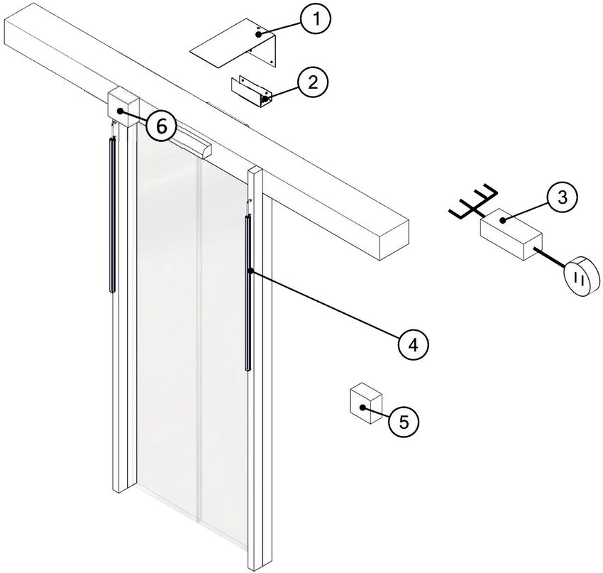
Example for 1-leaf sliding door
Pos. Components Pos. Components
1 Sensor bracket 2 Sensor
3 Control box 4 LED-Strips
5 Operating unit 6 Speaker (optional)
12 / 28 BAL_FlowControl_EN_1V3_REC_121-006454644Description 3
3.3 Function
record FlowControl is an automatic people screening system for retail stores and shops. The
system reliably counts all persons in both directions. If the pre-defined maximum number of
people is reached or exceeded, the entrance door is automatically deactivated to prevent fur-
ther intrusion of people. This enables active control and limitation of the flow of people into a
building.
Several door configurations (multiple door solution) are also possible. A surface-mounted LED
strip indicates the availability of the door for people.
Advantages:
– Savings in security and personnel costs
– Automatic stop of the flow of people when the predefined maximum number of people is reached
– Active control of the entrance door only in entry direction (escape direction not affected)
– Manually adjustable counter values (+ / -) and intuitive operation
– Only 2-4 hours installation work
– Clear signalisation with green/red LED strips (IP54), safe against vandalism
3.4 Authorization levels
NOTICE
The scope of the settings depends on the corresponding authorization level.
Manager – Available settings
– Max allowable people in store (Used to trigger customer traffic lights going red, disable of door opening and
triggering of audio alerts – see below)
– Pre-alert trigger for Customer Service Desk message as % of Max count (Staff alert is both custom audio mes-
sage and halo LED visual indicator around speaker. Can be set above 100% if needed)
– Delay time before “Please Wait Here” customer message will be retriggered
– Delay time before “Please Enter” customer message will retriggered
– System ON / OFF
– Exit only ON / OFF
– Voice alerts for customers ON / OFF. (“Please Wait Here” message plays every time count changes when
above MAX. “Please Enter” message plays whenever count drops below MAX count)
– Door interaction deactivation at MAX count ON / OFF
– Traffic light function ON / OFF (counting only function)
– Red Traffic Lights STEADY / FLASH / FAST FLASH
– + / - manual addition or reduction to total people count in store
– FlowControl BDE display brightness
– View last 15 total counts (Days if the system was powered off each night) + total overall count
Additional module Staff (option) – Available settings
– Push button override switch outside store to permit staff entry
– Volume adjustment for Customer Service audio alerts
– Temporary muting of Customer Service announcements for fixed period
– Disable of visual LED Halo Customer Service alert
BAL_FlowControl_EN_1V3_REC_121-006454644 13 / 283 Description
Engineer - Available settings
– Number of doors being monitored
– Sensor CAN bus addresses
– Sensor settings (Sensitivity, Sensor field boundaries, Object height, Sensor height)
– Language
– Show software version
3.5 Count data analysis and data transfer (optional)
Data-Box (optional) - Available settings
– With optional 2G/3G/4G/Wi-Fi interface
– Current number of people in store
– Current setting for MAX allowable people in store
– Total number of people who entered store (incl. and excl. manual adjustments made to count)
– Total number of people who left store (incl. and excl. manual adjustments made to count))
– + Manual adjustments made to count
– - Manual adjustments made to count
NOTICE
Remote Data: All data is live, currently updated once every 30 seconds
3.6 Operating modes
Display Operating mode Function Status
OFF Counting – Inactive
LED displays – Inactive
Interaction with door – Inactive
Current counter – Current counter value is set to zero
value
EXIT ONLY Counting – Active
LED displays – Red
Interaction with door – Exit only. Entrance radar inactive
COUNTING Counting – Active
002 / 050
LED displays – Green, when the maximum number of persons is
reached: Red.
Interaction with door – When max. number of persons reached: Only exit,
entrance radar inactive.
NOTICE
During system start-up, the counting is inactive, the LED displays are off and there is no inter-
action with the door. After initialization, the OFF mode is activated and the system is ready for
operation.
14 / 28 BAL_FlowControl_EN_1V3_REC_121-006454644Technical data 4
4 Technical data
System Specifications
Counting accuracy: > 99%
Counting technology: Time-of-Flight 3D
Counting statistics: Total Counter
Operation counter (15 entries)
Maximum number of sensors (combined): 4
Configuration layouts for several entrance/exit doors: Yes
Configurable count values: Yes (Actual and maximum number of persons is ad-
justable)
On/Off button: Yes
Operating unit: BDE-D FC
Interaction with sliding doors: Yes, all record doors plus third-party doors with radar
sensors (relay contacts)
Check compatibility with bus-connected radar sensors
on third-party doors
Mounting position LED strips: Exterior
Mounting position electronics: Interior
Mounting position sensor: Interior
Dimensions
Opening width A: max. 2200 mm at 3000 mm installation height
Passage height G: variable
Total height J: variable
Installation height of sensor: 2100 - 3000 mm
Min. object height to be counted: 1300 mm
Electrical connection data
Mains voltage (input): 110 - 230 V AC, 50-60 Hz
System voltage Peripherals: 24 V DC
Power consumption
System Max. 60 W
LED Strips 5 W per meter
Sensor 6 W per sensor
Control box 3W
Cable length, -extensions
Recommended cross-section LED strips 4 x 0.5mm²
Max. Cable length LED-strips 100 m
Max. Cable length BDE-D FC 80 m
Max. Cable length between first and last sensor:
With 2 sensors 120 m
With 3 sensors 100 m
With 4 sensors 60 m
VoiceBox (optional)
Mains voltage: 12 - 24 V
Power rating sound module: 10 W at 2 – 16 Ω
Potential-free inputs (voice output): 4
Speaker Output power: 25 W
BAL_FlowControl_EN_1V3_REC_121-006454644 15 / 284 Technical data
VoiceBox (optional)
Speaker Intendance: 4–8Ω
Speaker volume: 86 dB
Speaker frequency range: 90 – 17 000 Hz
Environmental conditions
Temperature range: -15°C to +50°C
Moisture range: up to 85% rel. humidity, non-condensing
Protection class: LED Strips IP65
Miscellaneous IP44
16 / 28 BAL_FlowControl_EN_1V3_REC_121-006454644Operation 5
5 Operation
5.1 BDE-D FC and key functions
The electronic operating unit BDE-D FC is an input and output unit for the con-
trol and parameterization of the number of persons. The LCD display with
C
background illumination provides information about the status with symbols
and plain text. Messages are shown on the display as text information.
002 / 050
E
Button Designation Function
ON / OFF – Switch system on / off
BACK – Exit menu item and change to the previous menu item
EXIT ONLY – Door opens only by activating the triggering device on the inside of the
door (radar).
MINUS – Navigation up when selecting the menu items
INFO – The INFO button is the access to the settings. Different settings are dis-
played depending on the authorization level (see chapter "Select Permis-
sion Level")
PLUS – Navigation down when selecting menu items
NOTICE
Menu display: In this area, the keys have the function printed above or below the keys (navig-
ation information).
Example: The INFO button has the function "E" (Enter / confirm input).
Button Designation Function
E ENTER – Select menu item
– Confirm entries within the menu display
CANCEL – Cancel entries within the menu display without saving
C
Display Designation Function
Symbol
CURRENT – Current number of people inside the building.
MAXIMUM – Maximum number of persons allowed inside the building.
BAL_FlowControl_EN_1V3_REC_121-006454644 17 / 285 Operation
5.2 Instructional symbols
NOTICE
If an information or an error message occurs, the display of the set operating mode remains
active. A corresponding symbol is also displayed.
It is also possible to display both symbols at the same time.
Instructional symbol Type
– Information
– Error
5.3 Menu display
NOTICE
You can switch to the menu display by briefly pressing the INFO Button 2x (double-
click).
The menu display is used to select the defined event groups (in- Menu
formation and errors) or the system information to call up the cor-
responding submenu. parameters
The display is as a list, the currently selected entry is inverted
(light text on dark background).
status
statistics
5.4 Status display
The status display shows information with status number and
message in plain text. If there is more than one piece of informa-
1/2
tion, the number and the current entry number is also displayed.
The next entry is called up by pressing the info key.
5.5 Select Permission Level
Select authorization level Manager
Press key sequence (double click) Description
– Settings for the manager e.g. setting the maximum number of per-
sons allowed
5.6 Restart via keyboard
Restart the controller
Press key sequence Display icon Description
E E – Press the INFO button for 5 seconds.
Reset control ? – Press the corresponding key to confirm.
C – Restart of the controller is performed.
No Yes
18 / 28 BAL_FlowControl_EN_1V3_REC_121-006454644Operation 5
Restart Hardware BDE-D FC
Press key sequence Display icon Description
E – Press the INFO 12 button for 12 seconds.
Welcome – Restart of the hardware is performed.
5.7 Operating lock via the keyboard
Locking the control unit
Press key sequence Display symbol Description
E – The control panel keys are locked.
– Unwanted manipulation of the control unit is
made more difficult.
C
– The locked state of BDE-D FC control unit
is displayed on the screen with a key sym-
bol (bottom left).
Unlocking the control unit
Press key sequence Display symbol Description
E – The control panel keys are activated.
– Free selection of operating modes and spe-
cial functions is again guaranteed.
C
BAL_FlowControl_EN_1V3_REC_121-006454644 19 / 285 Operation
5.8 BDE-D FC Menu
BDE-D FC Menu Menu item Default Description
Select the Manager authorisation level Parameters > Counting
Press key sequence (double-click) Max. no people 10 Setting the maximum number of persons allowed
Parameters > Signalisation
Door control ON ON = door is automatically deactivated when the person
limit is reached
From Software version 2.3.0 LED output ON ON = LED on in counting OFF = LED off in counting
mode mode
Menu LED blinking OFF ON = LEDs flash red when the counter reaches the set limit.
Blink duration 5s Duration of how long the LEDs flash. After that, continuous
parameters counting max. no. people light.
Blink Interval 500 ms Flashing frequency (speed of flashing)
signalisation door Contr.
Voice output ON ON/OFF Voice output
LED output
Repeat Pause 30 s Pause time of voice output message 1 (if max. pers.
LED blinking reached)
blink duration Repeat Pause OK 0s Pause time for voice output message 2 (if max. pers. is un-
blink interval derrun)
voice output % Alarm X 100% Output switches depending on the current counter reading
to max. number of persons
repeat delay
Parameters > BDE-D FC
repeat delay ok
Brightness 60% Adjusting the brightness of the display
%-Alarm 1 Contrast 40% Setting the display contrast
%-Alarm 2 Statistics
%-Alarm 3 Total counter n/a Continuously detects all passes in the direction of entry
Counter log n/a Records all counts in the direction of entry per usage (max.
BDE-D FC brightness 15 entries), switching off the machine creates a new entry
contrast Reset counter n/a Total counter and log counter are reset to 0
statistics total cnt. Status
cnt. log Status n/a Display of active status information
reset cnt.
state status
20 / 28 BAL_FlowControl_EN_1V3_REC_121-006454644Operation 5
5.9 Viewing and resetting counting statistics
NOTICE
Switching with the ON / OFF key , creates a new entry in the system (In-operation
Count).
A maximum of 15 entries are possible, after which a new entry replaces the oldest counter
value.
The user can retrieve and reset various counting statistics via the statistics
BDE-D FC.
total cnt.
cnt. log
reset cnt.
Viewing count statistics Total Count
Path Selection Description
Statistics n/a – The Total Count continuously records all
→ Total cnt. the passages in the entrance direction.
View Count Statistics In-operation Count
Path Selection Description
Statistics n/a – The In-operation Count records all counts
→ Cnt. Log in entrance direction per usage.
– Maximum 15 entries possible, the 16th
entry automatically overwrites the 1st entry.
Reset counting statistics
Path Selection Description
Statistics Yes – The Total Count is reset.
→ Reset cnt. No – All entries in In-operation Count are reset.
5.10 Setting the door control
In the menu Parameter / Signalling the door control can be activ- Signalisation
ated / deactivated when the person limit is reached.
Door Contr.
Activate / deactivate flashing function
Path Selection Description
Parameter off – If the function is activated, the door is auto-
→ Signalisation on matically deactivated when the person limit
is reached.
→ → Door control
– If the function is deactivated, the door is not
deactivated when the person limit is
reached.
BAL_FlowControl_EN_1V3_REC_121-006454644 21 / 285 Operation
5.11 Setting the LED Strips
The flashing of the LED strips can be activated and adjusted in signalisation
the Parameter / Signalisation menu. The blinking occurs when the
counter reaches the set limit. LED blinking
blink duration
blink interval
Activate / deactivate door control
Path Selection Description
Parameter off – If the function is activated, the door is auto-
→ Signalisation on matically deactivated when the person limit
is reached.
→ → Door control
– If the function is deactivated, the door is not
deactivated when the person limit is
reached.
Activate / deactivate LED display
Path Selection Description
Parameter off – When the function is activated, the LED
→ Signalisation on strips and the counting function are active.
→ → LED output – If the function is deactivated, only the count-
ing function is active.
Activate / deactivate flashing function
Path Selection Description
Parameter off – If the flashing function is activated, the LED
→ Signalisation on strips flash when the counter reaches the
set limit.
→ → LED blinking
Setting the flashing time of the LED strips
Path Selection Description
Parameter n/a – Duration, how long the LEDs blink until the
→ Signalisation next constant illumination
→ → Blink duration – Unit seconds.
Set flashing interval of LED strips
Path Selection Description
Parameter n/a – Setting the blinking frequency (speed of
→ Signalisation blinking).
→ → Blink Interval – Unit Milliseconds.
22 / 28 BAL_FlowControl_EN_1V3_REC_121-006454644Operation 5
5.12 Setting the Voice Box (Option)
In the menu Parameter / Signalisation the voice output can be ac- signalisation
tivated / deactivated and adjusted.
When the set personal limit is reached, a voice message is out- voice output
put. repeat delay
Example:„Please wait here“ repeat delay ok
Activate / deactivate voice output
Path Selection Description
Parameter off – As long as the current counter reading is
→ Signalisation on above the set limit, each counting process
will result in a further output of the voice
→ → Voice output message.
Set interval between speech output
Path Selection Description
Parameter n/a – Duration between each language output set
→ Signalisation in seconds.
→ → Repeat delay – The parameter "Repeat delay" is triggered
by reaching the maximum number of per-
sons.
Set interval between speech output
Path Selection Description
Parameter n/a – Duration between each language output set
→ Signalisation in seconds.
→ → Repeat delay ok – The parameter "Repeat delay OK" is
triggered when the maximum number of
persons is steps below.
Setting the volume of the voice output
Rotary wheel on the sound card Description
– The volume of the voice output can be ad-
justed on the rotary wheel of the sound
card.
– The sound card is located inside the Flow-
Control Box.
BAL_FlowControl_EN_1V3_REC_121-006454644 23 / 286 Servicing and maintenance
6 Servicing and maintenance
6.1 General remarks
According to the legal provision in force, the operating entity of the automatic door is responsible for
its maintenance and for the user's safety, as soon as the installation has been handed over.
The regular inspection of single elements by the operator requires little time investment and rein-
forces the prevention of accidents caused by an inappropriate use of the door.
Testing
As part of testing, visual and functional tests are conducted, ranging in particular over door leaves,
guides, bearings, limiting devices, sensors as well as over safety at danger points due to crushing,
shearing or drawing-in.
In addition, with door systems installed on escape routes, all the safety devices of the escape route
function are controlled.
To provide the operator with documentation and information, the test result is recorded on a check list
and must be kept in the logbook by the operator for at least one year.
Maintenance
During maintenance, bearings, sliding points and power transmission are cleaned and adjusted. Rel-
evant fixing screws are controlled and retightened if necessary.
Then, functional testing is carried out for switching devices, drives, control units, force or energy stor-
ing devices or command controllers. The safety devices are adjusted and all the motion sequences
including the final points are set.
A test run with final overall control of the door system is executed.
To provide the operator with documentation and information, the state of the door installation is recor-
ded on a check list and must be kept in the logbook by the operator for at least one year until the next
test / maintenance.
IMPORTANT
The test frequency is at least once a year according to the manufacturer's stipulations.
The maintenance frequency is at least twice a year according to the manufacturer's recom-
mendations.
IMPORTANT
A listing of recommended spare parts is supplied in the annex and is also available on re-
quest at your service department.
IMPORTANT
Tests and maintenance should only be carried out by a specialist or a person specifically
trained for that. The authorisation of these persons exclusively lies with the manufacturer. Ex-
tent, results and time of the periodical inspection must be recorded in the logbook. These re-
cords must be kept by the operator.
24 / 28 BAL_FlowControl_EN_1V3_REC_121-006454644Servicing and maintenance 6
6.2 Monthly inspection work to be carried out by the operating company
The monthly inspection and maintenance of individual components by the operator requires little time
and serves the reliable function, increased service life and operational safety of the installation.
Test / inspection Procedure Expected result
Sensors and LED strips – Walk towards the door at normal – The sensor must cover the entire
speed (from the inside and out- passage width.
side). – LED strips indicate the correct
– If necessary, clean the sensors status.
and LED strips. – The door is opened at an early
– Please note: Moisture condensa- stage and at an appropriate
tion on the sensor, due to the es- speed to allow unhindered pas-
cape of warm, moist internal air sage.
and condensation on the colder
external motion sensor, can pre-
vent the door from closing. Dehu-
midify the interior air or wipe the
outer sensor dry if necessary.
BAL_FlowControl_EN_1V3_REC_121-006454644 25 / 287 Malfunctions
7 Malfunctions
7.1 Behavior in event of faults
In the event of an irregularity or malfunction, different displays are shown depending on the control
unit connected.
IMPORTANT
If malfunctions that endanger the safety of individuals occur, the system must be turned off. It
may not be turned back on until the problem has been resolved by a professional and the
danger no long exists.
NOTICE
If the door performs a slow opening or closing movement, it may be a deliberate automatic re-
dundancy test.
7.1.1 Malfunction indication
NOTICE
In some cases, malfunctions can be remedied by the operator himself. If the operator does
not remedy the fault, please contact the responsible service centre.
Before you call, please make a note of the information which is shown on the display of the
BDE-D FC operating unit. This information gives the service technician important information
for possible troubleshooting.
Malfunction Display icon Description
Error display – Error is pending.
– Contact Service.
No indication – Check connections.
– Contact Service.
CAN malfunction – No connection to the controller.
– Contact Service.
7.1.2 Possible troubleshooting
– Based on the status display, malfunctions can be partially corrected by the user.
– If you are not sure, please contact the responsible service centre.
– Before you call, write down the data displayed on the BDE-D FC. These information give the tech-
nician important information for a possible troubleshooting.
– You can navigate from one malfunction to another by pressing the INFO button 2x quickly.
Example:
Which information? How displayed? (Ex- Procedure
ample)
Malfunction ! – Is automatically displayed on the control
unit
Software versions Menu – By pressing the INFO button 2x quickly, you
parameters can access the settings. Then go to the
status menu item [version].
software
!
26 / 28 BAL_FlowControl_EN_1V3_REC_121-006454644Taking out of service and disposal 8
8 Taking out of service and disposal
8.1 Decommissioning
When shutting down or taking out of service, the system is disconnected from the mains supply and
any existing battery is unplugged.
NOTICE
After each temporary shutdown a new commissioning must be carried out.
8.2 Dismantling and disposal
IMPORTANT
All machine parts must be sorted by type of material and disposed of according to
local regulations and guidelines.
NOTICE
The door systems can be completely disassembled in reverse order.
The automatic door mainly consists of the following materials:
Aluminum:
– Linking profiles
– Gearbox, Drive panel
– Door wing profiles and side profiles
– Various profiles and small parts
Steel / iron parts:
– Stainless steel casing, Floor panel, Box recess for floor installation
– Optional spacer or reinforcement profiles
– Gear components, springs
– Various small parts like fittings, covers, linking parts, etc.
Glass:
– Door wings and side panels
Various electronic and electromechanical components:
– Sensors, control and operator components
– Lead batteries and nickel-cadmium rechargeable batteries
Various plastics:
– Rollers
– Cable clips, coupling and linking parts
– Sealing profiles
– Casing of electromechanical components and sensors
BAL_FlowControl_EN_1V3_REC_121-006454644 27 / 28Australia
www.recorddoors.com.au
Canada
www.recorddoors.com
China
www.record.net.cn
Deutschland
www.record.de
Denmark
www.record-danmark.dk
España
www.record.es
France
www.record.fr
Great Britain
www.recorduk.co.uk
Malaysia
www.recorddoors.my
Polska
pl.record.global
Schweiz
www.record.ch
Sverige
www.record.se
Türkiye
tr.record.global
United States
www.recorddoors.com
record global export
www.record.global
record Group
www.record.group
Subject to technical modifications
Copyright © agtatec ag
No. 121-006454644You can also read