RED CAP ENERGY NUWEVELD NORTH WIND FARM - TRAFFIC IMPACT ASSESSMENT - Zutari
←
→
Page content transcription
If your browser does not render page correctly, please read the page content below
RED CAP ENERGY
 NUWEVELD NORTH WIND FARM
       TRAFFIC IMPACT ASSESSMENT

   Report prepared for:                       Report prepared by:

 Red Cap Energy (Pty) Ltd                        Athol Schwarz
             of                                        of
Unit B2, Mainstream Centre,                      45 Raven St,
         Main Road,                               West Beach,
          Hout Bay                                Table View
           7806                                      7441

Phone: +27 (0) 21 790 1392                 Mobile: +27 (0) 82 777 1961

Email: Lance@red-cap.co.za               Email: schwarzathol@gmail.com

          Impact Assessment Report (Rev 3) – 14th April 2021
CONTENT
Topic                                                                                                                                                  Page
1     EXECUTIVE SUMMARY ........................................................................................................................ 1
2     PROJECT SPECIFICATIONS ................................................................................................................ 2
3     ABBREVIATIONS ................................................................................................................................... 4
4     GLOSSARY ............................................................................................................................................ 4
5     INTRODUCTION ..................................................................................................................................... 4
      5.1 TERMS OF REFERENCE ............................................................................................................ 4
      5.2 SCOPE AND OBJECTIVES.......................................................................................................... 5
           5.2.1 Scope .................................................................................................................................. 5
           5.2.2 Objectives ........................................................................................................................... 5
      5.3 LEGISLATION AND PERMIT REQUIREMENTS ......................................................................... 6
           5.3.1 Roads .................................................................................................................................. 6
           5.3.2 Vehicle Dimensions ............................................................................................................ 6
           5.3.3 Vehicle Loads ..................................................................................................................... 7
           5.3.4 Abnormal Loads .................................................................................................................. 7
      5.4 METHODOLOGY .......................................................................................................................... 8
      5.5 ASSUMPTIONS ............................................................................................................................ 8
      5.6 LIMITATIONS ................................................................................................................................ 9
      5.7 SOURCE OF INFORMATION....................................................................................................... 9
6     DESCRIPTION OF THE AFFECTED ENVIRONMENT ........................................................................ 10
      6.1 ROAD NETWORK ...................................................................................................................... 10
           6.1.1 N1 National Road .............................................................................................................. 11
           6.1.2 N12 National Roads .......................................................................................................... 11
           6.1.3 R63 (TR016) ..................................................................................................................... 12
           6.1.4 R381 (TR05801) ............................................................................................................... 12
           6.1.5 DR02311 ........................................................................................................................... 13
           6.1.6 DR02317 ........................................................................................................................... 14
      6.2 SITE ACCESS............................................................................................................................. 15
      6.3 TRANSPORTATION ROUTES ................................................................................................... 17
           6.3.1 Commuter Routes ............................................................................................................. 17
           6.3.2 Freight Routes .................................................................................................................. 18
      6.4 EXISTING WIND FARMS ........................................................................................................... 20
      6.5 FUTURE WIND FARMS ............................................................................................................. 21
           6.5.1 Nuweveld West Wind Farm .............................................................................................. 21
           6.5.2 Nuweveld East Wind Farm ............................................................................................... 21
           6.5.3 Nuweveld Grid Connection ............................................................................................... 21
7     TRAFFIC VOLUMES ............................................................................................................................ 21
      7.1 STATUS QUO ............................................................................................................................. 22
           7.1.1 Road Classification ........................................................................................................... 22
           7.1.2 Counting Stations .............................................................................................................. 22
           7.1.3 Baseline Traffic Volumes .................................................................................................. 31
      7.2 CONSTRUCTION PHASE .......................................................................................................... 31
           7.2.1 Peak Traffic ....................................................................................................................... 32
           7.2.2 Diurnal Traffic .................................................................................................................... 34
      7.3 OPERATIONAL PHASE ............................................................................................................. 39
           7.3.1 Peak Traffic ....................................................................................................................... 39
           7.3.2 Diurnal Traffic .................................................................................................................... 39
      7.4 DECOMMISSIONING PHASE .................................................................................................... 40
8     ASSESSMENT OF IMPACTS .............................................................................................................. 40
      8.1 CONSTRUCTION PHASE .......................................................................................................... 40
      8.2 OPERATIONAL PHASE ............................................................................................................. 42
      8.3 DECOMMISSIONING PHASE .................................................................................................... 43
9     ASSESSMENT OF CUMULATIVE IMPACTS ...................................................................................... 43
      9.1 CONSTRUCTION PHASE .......................................................................................................... 44
      9.2 OPERATIONAL PHASE ............................................................................................................. 45
      9.3 DECOMMISSIONING PHASE .................................................................................................... 46
10    RISKS AND IMPACTS ......................................................................................................................... 46
      10.1 RISKS .......................................................................................................................................... 47
           10.1.1 Traffic Volumes ................................................................................................................. 47
           10.1.2 Road Condition ................................................................................................................. 47
           10.1.3 Reduced Visibility .............................................................................................................. 47
           10.1.4 Pedestrians and Animals .................................................................................................. 48
10.2 IMPACTS .................................................................................................................................... 48
          10.2.1 Construction Phase ........................................................................................................... 48
          10.2.2 Operational Phase ............................................................................................................ 51
          10.2.3 Decommissioning Phase .................................................................................................. 52
          10.2.4 Cumulative Impacts .......................................................................................................... 52
          10.2.5 No-go Alternative .............................................................................................................. 56
          10.2.6 Impact Summary ............................................................................................................... 56
11  CONCLUSION AND RECOMMENDATIONS ....................................................................................... 56
    11.1 CONCLUSION ............................................................................................................................ 57
    11.2 RECOMMENDATIONS ............................................................................................................... 59
12  APPENDICES ....................................................................................................................................... 61
APPENDIX 1 - DECLARATION ...................................................................................................................... 62
APPENDIX 2 - NEMA REQUIREMENTS FOR SPECIALIST REPORTS ...................................................... 63
APPENDIX 3 - CURRICULUM VITAE ............................................................................................................ 64

                                                                LIST OF TABLES
                                                                                                                                                           Page
Table 1 - Synopsis of Project Specifications ..................................................................................................... 2
Table 2 - List of Abbreviations ........................................................................................................................... 4
Table 3 - Definitions ........................................................................................................................................... 4
Table 4 - R381 Road Details ........................................................................................................................... 12
Table 5 - Distance to Surrounding Towns ....................................................................................................... 18
Table 6 - Possible Commuter Route Details ................................................................................................... 18
Table 7 - Possible Freight Route Details ......................................................................................................... 18
Table 8 - Household Demographics ................................................................................................................ 33
Table 9 - Construction Phase – Peak Traffic ................................................................................................... 34
Table 10 - Construction Phase – Diurnal Traffic ............................................................................................. 38
Table 11 - Operational Phase – Peak Traffic .................................................................................................. 39
Table 12 - Operational Phase – Diurnal Traffic ............................................................................................... 40
Table 13 - Construction Phase – Traffic Volumes ........................................................................................... 41
Table 14 - Construction Phase - Traffic Assessment ...................................................................................... 41
Table 15 - Operational Phase – Traffic Volumes ............................................................................................ 42
Table 16 - Operational Phase - Traffic Assessment ........................................................................................ 43
Table 17 - Cumulative Peak Constructional Phase - Traffic Volume .............................................................. 44
Table 18 - Cumulative Constructional Phase - Traffic Assessment ................................................................ 44
Table 19 - Cumulated Operational Phase – Traffic Volumes .......................................................................... 45
Table 20 - Cumulative Operational Phase – Traffic Assessment .................................................................... 46
Table 21 - Construction Phase - Increased Road Incidents ............................................................................ 48
Table 22 - Construction Phase - Road Degradation ....................................................................................... 49
Table 23 - Construction Phase - Dust ............................................................................................................. 50
Table 24 - Construction Phase – Intersection Safety ...................................................................................... 51
Table 25 - Operational Phase – Intersection Safety ........................................................................................ 52
Table 26 - Cumulative Impact - Increased Road Incidents ............................................................................. 53
Table 27 - Cumulative Impact – Road Degradation ........................................................................................ 53
Table 28 - Cumulative Impact - Dust ............................................................................................................... 54
Table 29 - Cumulative Impact – Intersection Safety ........................................................................................ 55
Table 30 - Impact Summary ............................................................................................................................ 56

                                                                LIST OF FIGURES
                                                                                                                                                        Page
Figure 1 - Nuweveld North Wind Farm Site ....................................................................................................... 5
Figure 2 - Road Network.................................................................................................................................. 10
Figure 3 - N1 (East of Beaufort West) ............................................................................................................. 11
Figure 4 - N12 (South of Victoria West) ........................................................................................................... 11
Figure 5 - R63 (East of Loxton ........................................................................................................................ 12
Figure 6 - Paved Section of R381 ................................................................................................................... 13
Figure 7 - Unpaved Section of R381 ............................................................................................................... 13
Figure 8 - De Jager's Pass on DR02311 ......................................................................................................... 14
Figure 9 - DR02317 ......................................................................................................................................... 14
Figure 10 - DR02317 8 km from R381 ............................................................................................................ 15
Figure 11 - DR02317 22 km from R381 .......................................................................................................... 15
Figure 12 - Potential WTG Layout ................................................................................................................... 15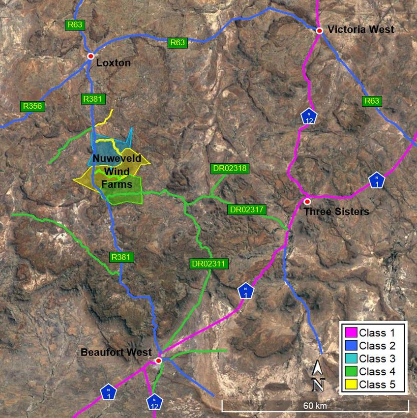
Figure 13 - Potential WTG Units East of R381 ................................................................................................ 16
Figure 14 - Southern Entrance ........................................................................................................................ 16
Figure 15 - Northern Entrance ......................................................................................................................... 17
Figure 16 - Surrounding Towns ....................................................................................................................... 17
Figure 17 - Potential By-Pass North of Beaufort West .................................................................................... 19
Figure 18 - Existing Wind Energy Facility ........................................................................................................ 20
Figure 19 - Future Wind Farms and Grid Connection ..................................................................................... 21
Figure 20 - Road Classification ....................................................................................................................... 22
Figure 21 - Counting Station ............................................................................................................................ 23
Figure 22 - Traffic Distribution on the N1 at Counting Station 2146 ................................................................ 23
Figure 23 - Traffic Distribution on the R381 at Counting Station 2146 ............................................................ 24
Figure 24 - Traffic Distribution on the R381 at Counting Station 2147 ............................................................ 24
Figure 25 - Traffic Distribution on the R381 at Counting Station 2148 ............................................................ 25
Figure 26 - Traffic Distribution on the DR02317 at Counting Station 2148 ..................................................... 25
Figure 27 - Traffic Distribution on the R381 at Counting Station 2149 ............................................................ 25
Figure 29 - Traffic Distribution on the R381 at Counting Station 2150 ............................................................ 26
Figure 30 - Traffic Distribution on the N1 at Counting Station 2758 ................................................................ 26
Figure 31 - Traffic Distribution on the DR02311 at Counting Station 2158 ..................................................... 27
Figure 32 - Traffic Distribution on the DR02311 at Counting Station 2759 ..................................................... 27
Figure 33 - Traffic Distribution on the DR02317 at Counting Station 2759 ..................................................... 27
Figure 34 - Traffic Distribution on the DR02317 at Counting Station 2764 ..................................................... 28
Figure 35 - Traffic Distribution on the N1 at Counting Station 2765 ................................................................ 28
Figure 36 - Traffic Distribution on the DR02317 at Counting Station 2765 ..................................................... 29
Figure 37 - Traffic Distribution on the N1 at Counting Station 2781 ................................................................ 29
Figure 38 - Traffic Distribution on the N12 at Counting Station 19350 ............................................................ 30
Figure 39 - Traffic Distribution on the R63 at Counting Station M13521 ......................................................... 30
Figure 40 - Baseline AADT .............................................................................................................................. 31
Figure 41 - Bulk Cement Tanker and Pup ....................................................................................................... 36
Figure 42 - Articulated Rear Tipper ................................................................................................................. 36
Figure 43 - Transportation of Turbine Blade ................................................................................................... 37
Figure 44 - Transportation of Nacelle .............................................................................................................. 37
Document Control
    Revision             Date                           Description                                     Author

     Rev 0         22nd Mar 2020                       Issued for use                              Athol Schwarz

                                       Revised report to include the effect of the
     Rev 1          26th Jun 2020       Battery Storage Facility on each of the                    Athol Schwarz
                                                     Wind Farms.

                                      Report amended to reflect reduced number
     Rev 2         18th Sep 2020                                                                   Athol Schwarz
                                        of WTG and revised boundary layout.

                                         Revised report to Assessment Phases
     Rev 3          14th Apr 2021                                                                  Athol Schwarz
                                                         Status

                                                     DISCLAIMER
This report has been prepared for the exclusive use and benefit of Red Cap Energy (Pty) Ltd (the “Client”) as part of an
Agreement and subjected to the following disclaimer:
This report (including any enclosures and attachments) may be used by the Client within the framework of the Agreement
and shall not be used by any other party nor for any other purpose without the written consent of the Author. The Client
indemnifies the Author against any liability, loss, damage, or cost howsoever arising, including by way of a third-party claim,
from a breach of this undertaking by the Client. The findings, conclusions and opinions of the Author, therefore, on the
scope of the Agreement between the Author and the Client. Portions of the Reports may be of a privileged and confidential
nature relating to the Agreement. The Author accepts no responsibility for damages, if any, suffered by any third party as
a result of decisions made or actions based on the Reports. While it is believed that the information contained in the Report
is reliable under the conditions and subject to the limitations outlined in the Agreements, the Report will be based in part
on information not within the control of the Author and the Author, therefore, cannot and does not guarantee its accuracy.
Unless otherwise expressly stated, the analyses contained in the Reports will be developed from information provided by
the Client. The Author will not audit such information and the Author makes no representations as to the validity or accuracy
thereof. The comments in the Reports will reflect the Author’s best judgement in light of the information available at the
time of preparation. The Author will have conducted an investigation required in terms of the aforementioned scope of the
Agreements.
While all professional care has been undertaken in preparation of this Report, the Author accepts no liability for loss or
damages incurred as a result of reliance placed upon its content.
1        EXECUTIVE SUMMARY
         Red Cap Energy (Pty) Ltd is proposing to develop three Wind Farms and associated
         Grid Connection (shared infrastructure between the three wind farms), north of
         Beaufort West within the Central Karoo District Municipality of the Western Cape.
         The proposed wind farms are, the Nuweveld North Wind Farm, the Nuweveld East
         Wind Farm and the Nuweveld West Wind Farm and are collectively referred to as the
         Nuweveld Wind Farms.
         This Traffic Impact Assessment has been produced as part of an iterative design
         process being undertaken for this project. As part of this process, various design and
         layout options have been considered, assessed and further refined to ensure
         adherence to the environmental and technical constraints present on site. Previous
         processes include a Screening Phase and a Pre-Application Scoping Phase which
         included the production and distribution of a Pre-application Scoping Report.
         Specialist recommendations made to further refine the design and layout of the
         project were included in the Pre-application Scoping Report. The refined design and
         layout that resulted from the Pre-App Scoping Phase is what has been assessed in
         this report and the findings of this report will inform that outcomes of the Scoping
         Phase of this project.
         As part of the Environmental Impact Assessment process, a Traffic Impact
         Assessment for each of the wind farms developments and grid connection is to be
         provided. This Traffic Impact Assessment is for Nuweveld North Wind Farm,
         hereafter referred to as 'the development'. Based on the latest available information,
         the development will consist of up to a maximum of thirty-five wind turbine generator
         units, the generating capacity of which is still undefined as the appointment of the
         turbine supplier has not been finalised.
         This Traffic Impact Assessment was undertaken by Mr A. Schwarz, by following the
         relevant guidelines, to provide a technical appraisal of the traffic impact of the
         development on the existing road network, during the construction, operation and
         decommissioning phases of the development. A site visit was conducted during
         September 2019 and together with traffic count data forms the basis of this
         assessment.
         The proposed transportation access routes that are to be used for the transportation
         of equipment and material, including abnormal loads, for this development, are on
         national roads and are well-established transportation routes.
         Traffic generation estimates used in this assessment is based on the experience of
         similar projects. The worst-case scenario for the cumulative impact has been
         adopted, which assumes all three of the wind farms are constructed simultaneously,
         over a period of two-years. The most significant increase in traffic will result from the
         daily commuting of personnel, to and from the site during peak traffic. The projected
         increase in traffic on the R381 is less than fifty vehicles per hour, the threshold as
         stipulated in the South African Traffic Impact and Site Traffic Assessment Manual
         (2012).
         There will be a notable increase in traffic volumes on the road network during the
         construction phase of this development, and less conspicuous during the operational
         phase. This report has assessed the impact of the additional traffic on the
         surrounding road network and found that the existing road network is currently
         operating at well below its capacity and provides an adequate level of service. The
         increase in traffic volumes will lead to greater wear and tear especially during the

NUWEVELD NORTH WIND FARM - TIA (Rev 3).docx                                                Page 1
construction phase of the development but will not have an undue detrimental impact
         on the structural integrity of the roads within the study area. Due to budgetary
         constraints within various spheres of government, nominal maintenance is
         undertaken on the road network. To this end, it is strongly suggested that the
         developer contributes towards the ongoing maintenance of the road network
         associated with the various phases of the development.
         In addition, there are several gravel sections on the R381, through mountain passes,
         which are extremely treacherous and pose a potential risk to road users transporting
         staff to and from the site. These areas, with the approval of the local road authorities,
         will have to be addressed by the developer.
         It should be noted that it is not possible to determine the expected traffic volumes that
         will be generated during the decommissioning phase. It can, however, be expected
         that these volumes will be lower than during the construction phase. As part of the
         decommissioning process, a separate traffic impact assessment should be
         undertaken since many of the characteristics related to the traffic impact assessment,
         i.e. access routes, road geometry, traffic volumes, etc. would have changed over the
         operational life of the development.
         A range of management and mitigation strategies are identified for implementation
         during the construction and operation phases of the development to minimise traffic
         impacts, reduce community disruption and the risk of traffic incidents.
         Thus, from a traffic and transportation perspective, there are no constraints or notable
         impacts that would jeopardise the implementation of this development.

2        PROJECT SPECIFICATIONS
         A synopsis of the project specification for Nuweveld North Wind Farm are provided in
         Table 1.
                                         Table 1 - Synopsis of Project Specifications
              Project                                                                                 Estimated
            Components                         Specifications & Footprint areas                       Combined
            Description                                                                              Footprint (ha)
         Location              Approximately 65km north of Beaufort West and approximately 30km
                               south of Loxton along the R381. Land use of the site and surrounding
                               properties comprise of low density livestock farming (grazing). Total
                               Wind farm area is 10144ha
         Wind Turbines         37 potential turbine locations assessed for approval but only up to a
                               maximum of 35 wind turbines will be constructed.
                               No Turbines are located to the West of the R381.
                               Turbine envelope:
                                   Rotor diameter: 110m to 190m (up to 95m blade / radius)
                                   Hub height: 80m to 150m
                                   Rotor top tip height: 140m to 245m (maximum based on 150m hub
                                   + 95m blade = 245m)
                                   Rotor bottom tip height: minimum of 25 m (and not lower).
                               Generation capacity: up to maximum of 8MW output per turbine
                               Nuweveld North has a targeted nameplate capacity of up to a
                               maximum of 280MW.
         Turbine               Each turbine will have a circular foundation with a diameter of up to
         Foundations           32m and this will be placed alongside the 40m wide hardstand
                                                                                                     4.5ha (permanent)
                               resulting in an area of about 40mx32m that will be permanently
                               disturbed for the turbine foundation.
         Turbine               Each turbine will have a hardstand of 80m x 40m.                            11.2ha
         Hardstands                                                                                     (permanent)
         Cabling               Turbines to be connected to on-site substation via 33kV cables. 1.8ha (temporary)
                               Cables to be laid underground in trenches mainly adjacent to roads or
                               overhead via 33kV monopoles where burying is not possible due to
                               technical, geological, environmental or topographical constraints

NUWEVELD NORTH WIND FARM - TIA (Rev 3).docx                                                                    Page 2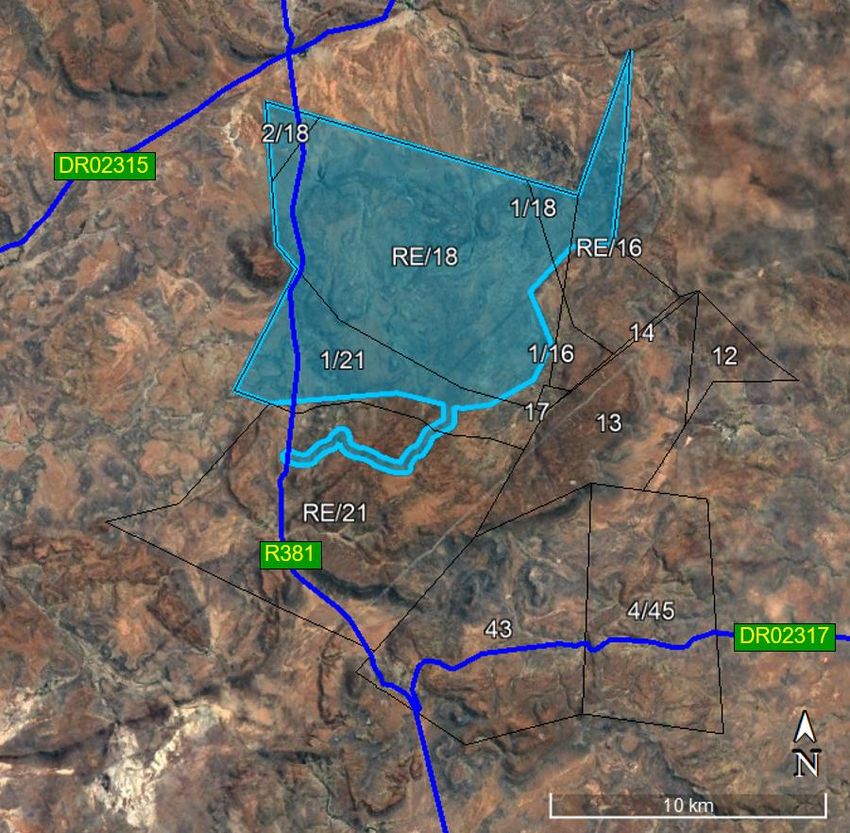
Project                                                                                    Estimated
            Components                          Specifications & Footprint areas                         Combined
            Description                                                                                 Footprint (ha)
                               The length of the cabling that is not adjacent to the wind farm roads is
                               6.1km but of this about 1.2km is running along an existing track thus
                               reducing the impact. The potential area impacted is recorded here for
                               the off-road cables and those sections that run along proposed wind
                               farm roads are covered within the temporary road disturbance
                               footprint, see below.
         Internal WEF          3.4km of 33kV overhead powerline with pylons of up to 20m high. The
         overhead              majority of this (2.3km) will be running next to the proposed Eskom
                                                                                                         1ha (permanent)
         powerlines            grid connection ensuring the majority of the internal overhead line
                               impacts are in the same corridor as the proposed grid connection.
         Site roads            Permanent roads will be 6m wide and may require side drains on one
                               or both sides. All roads may have underground cables running next to
                               them. A 12m wide road corridor may be temporary impacted during               ≤54-65ha
                               construction and rehabilitated to 6m wide after construction. For           (permanent)*
                               Nuweveld North a total road network of about 76,4km is proposed and            ≤46ha
                               the area impacted is presented here. Of this 76,4km, a total of 19km        (temporary)*
                               is shared infrastructure with Nuweveld West & Nuweveld East Wind
                               Farms.
         N1 Bypass Road        A temporary bypass road is required on the N1 to avoid the town of
         (shared               Beaufort West with the major Wind Farm components. The road will
         infrastructure)       be up to 6m wide but a 12m wide road corridor may be temporary 6.8ha (temporary)
                               impacted during construction and rehabilitated once construction is
                               complete. The length of the temporary road will be about 5.7km of
                               which about 2.5km is along an existing track. This road will be shared
                               by all three Wind Farm (Nuweveld East, West and North
                               Wind farm will have a 150m x 75m substation yard which includes an
                               Operation and Maintenance (O&M) building, Substation building and
         Wind farm
                               a High Voltage Gantry as well as a 2.4 ha area for battery storage
         Substations and                                                                                3.6ha (permanent)
                               facility which may be adjacent or slightly removed from the substation
         battery facility
                               depending on the local constraints. The substation and battery facility
                               will be connected by an underground or overhead cable
         Operations and        The O&M area will include all offices, stores, workshops, laydown area
                               Building & Substation building will be housed in the substation yard.       Forms part of
         maintenance
                                                                                                         Substation yard
         (O&M) area
         Security              Security gate and hut to be installed at entrance to site.
                               No fencing around individual turbines, existing fencing shall remain
                               around perimeter of properties.                                               20m2
                               Temporary and permanent yard areas to be enclosed (with access
                               control) with an up to 2.4m high fence.
         Temporary        Wind farm temporary construction areas:
         laydown, staging    Temporary site camp/s areas: 20 000m2
         and yards areas     Batching plant area of approximately 2 000m2                         2.2ha (temporary)
         required for the
         construction /      Each wind farm will have a bunded fuel & lubricants storage facility
         decommissioning     on site in fixed tanks not exceeding 80m3 (situated at the site
         phase.              camp).
                          Individual turbine temporary laydown areas including crane boom               17.5ha
                          laydown areas, blade laydown areas and other potential temporary           (temporary)
                          areas will be up to a maximum of 5 000m2
                                                                                                          75ha temporary
                                                                            Total disturbance footprint and 84ha
                                                                                                          permanent*
         *These areas represent more than will be impacted given the road values are based on all thirty-seven turbines
         being constructed where in reality only thirty-five turbines will be developed as part of this application.

NUWEVELD NORTH WIND FARM - TIA (Rev 3).docx                                                                      Page 3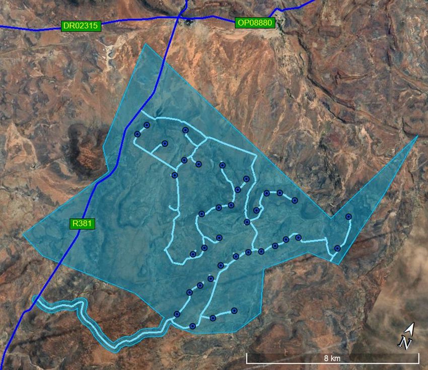
3        ABBREVIATIONS
         The following abbreviations have been used in this document.
                                                  Table 2 - List of Abbreviations
               Abbreviation                                                  Meaning
                   AADT             Average Annual Daily Traffic
                   ADT              Average Daily Traffic
                   DEA              Department of Environmental Affairs
                    EIA             Environmental Impact Assessment
                  EPCM              Engineering, Procurement, Construction and Management
                    IAP             Interested and Affected Parties
                   km/h             Kilometre per hour
                   LOS              Level of Service
                    MW              Megawatt
                  NEMA              National Environmental Management Act
                   O&M              Operation and Maintenance
                   PDP              Professional Driving Permit
                   RNIS             Road Network Information System
                 SANRAL             South African National Roads Agency SOC Ltd
                   TMP              Traffic Management Plan
                    vph             Vehicle per hour
                   WTG              Wind Turbine Generator

4        GLOSSARY
         The following definitions apply to these words which have been used in this
         document.
                                                        Table 3 - Definitions
                                                               Definitions
               R381 (North)         refers to the section of the R381, between Loxton and the development.
               R381 (South)         refers to the section of the R381, between Beaufort West and the development.
           Average Annual Daily     is the total traffic volume (in both directions) generated in a year, including school and
                 Traffic            public holidays and weekends, divided by the number of days in the year.
                                    is the total traffic (in both directions) generated in a twenty-four-hour period, on a
           Average Daily Traffic
                                    typical working weekday.
                  Diurnal           means happening or active during the daytime.
                Peak Traffic        traffic at the time it is most busy.
                                    is the number of vehicles passing a specific point in a given time, expressed in vehicles
              Traffic Volume
                                    per hour.
                                    is defined as a single (one-directional) movement with either the destination or the
                    Trip
                                    origin of the trip at a development.

5        INTRODUCTION
5.1      TERMS OF REFERENCE
         Red Cap Energy (Pty) Ltd appointed Mr A. Schwarz, to provide a Traffic Impact
         Assessment (TIA) for the proposed Nuweveld North Wind Farm, within the Central
         Karoo Municipality District of the Western Cape. The extent of the site on which the
         development is to be constructed and access servitude is shown in Figure 1,
         hereafter referred to as 'the site'.

NUWEVELD NORTH WIND FARM - TIA (Rev 3).docx                                                                           Page 4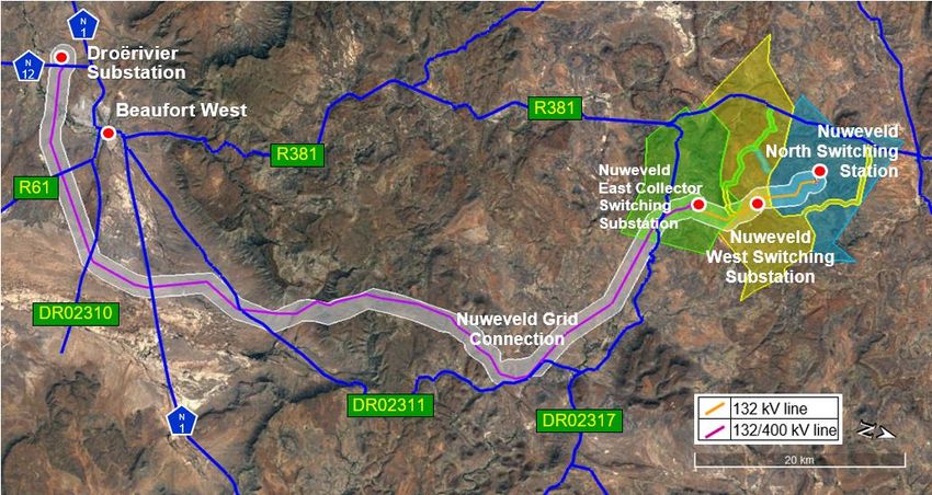
Figure 1 - Nuweveld North Wind Farm Site
         This Traffic Impact Assessment forms an integral part of the supporting
         documentation required for the Environmental Impact Assessment application to the
         Department of Environmental Affairs.
5.2      SCOPE AND OBJECTIVES

5.2.1 Scope
         Red Cap Energy (Pty) Ltd propose developing a wind farm, called Nuweveld North
         Wind Farm. The wind farm shall consist of up to a maximum of thirty-five Wind
         Turbine Generator (WTG) units which will be selected from the current forty-two
         potential turbine locations identified.
         The scope of this report includes, inter alia:
         • Identify the potential road network that could be affected by this development;
         • Determine a traffic baseline against which the potential traffic impacts are to be
           measured;
         • Identify potential impacts and cumulative impacts that may occur during the
           construction, operational and decommissioning phases of the development;
         • Determine mitigation and/or management measures which could be implemented,
           to, as far as possible, reduce the effect of negative impacts; and
         • Incorporate and address all issues and concerns raised by Interested and Affected
           Parties, (if and when applicable).

5.2.2 Objectives
         The objective of this report is to determine the potential traffic impact, that the
         development will have on the existing road network.

NUWEVELD NORTH WIND FARM - TIA (Rev 3).docx                                           Page 5
5.3 LEGISLATION AND PERMIT REQUIREMENTS
The overarching environmental legislation for the management of the environment in
South Africa, is the National Environmental Management Act, 1998 (Act 107 of 1998
“NEMA”). Its preamble states that sustainable development requires the integration
of social, economic and environmental factors in the planning, implementation and
evaluation of environmental decisions to ensure that the development serves present
and future generations.
Traffic impacts are therefore an important aspect to be considered in the decision-
making of developments.
5.3.1 Roads
The relevant legislation associated with the road (infrastructure), transportation and
traffic include, inter alia:
• National Water Act (Act 36 of 1998), with regards to all crossings of watercourses;
• National Road Traffic Act (Act 93 of 1996);
• Advertising on Road and Ribbon Development Act (Act 21 of 1940):
- Regulates the display of advertisements outside certain urban areas at places
visible from public roads, and the depositing or leaving of disused machinery or
refuse and the erection, construction or laying of structures and other things
near certain public roads, and the access to certain land from such roads;
- Section 9: Prohibition of the erection of structures near-certain roads;
- Section 9A: Prohibition of the erection of structures or construction of other
things near intersections of certain roads;
- Section 10: Restriction of access to land through a fence, etc., along certain
roads.
• Roads Ordinance Number 19 of 1976:
- Consolidate and amend the law relating to public roads and public paths and to
provide for matters incidental thereto;
- Section 13: Erection of gates across public roads and public paths;
- Section 17: Erection of structures on or near public roads;
- Section 18: Access to and exit from certain public roads and public paths.
5.3.2 Vehicle Dimensions
Regulations 221 to 230 of the National Road Traffic Act relates to vehicle dimensions,
the most salient points are summarised below.
Regulation 221: Defines the legislation requirements regarding the overall length of
vehicles, and is summarised as follows:
• a rigid vehicle shall not exceed 12.5 m;
• articulated motor vehicle and semi-trailers shall not exceed 18.5 m;
• other combination of motor vehicles (including interlinks, multiple trailers, etc.) shall
not exceed 22.0 m;
Regulation 223: Defines the legislation requirements regarding the overall width of
vehicles with a gross mass of 12 000 kilograms or more, shall not exceed 2.6 m.
Regulation 224: Define the legislative requirements regarding the overall height of a
vehicle and transported load, which shall not exceed 4.3 m.
NUWEVELD NORTH WIND FARM - TIA (Rev 3).docx Page 6Regulation 225: Defines the legislation requirements regarding the maximum turning
radius and wheelbase, which shall not exceed 13.1 m or 10.0 m (for a semi-trailer)
respectively.
5.3.3 Vehicle Loads
Regulations 231 to 249 of the National Road Traffic Act relates to vehicles loads, the
most salient points are summarised below.
Regulation 240: Defines the legislation requirements regarding the mass load
carrying capacity on roads, the most relevant points are summarised below:
• The mass load of a wheel fitted to a steering axle shall not exceed 3 850 kg, others
shall not exceed 4 000 kg;
• The mass load of an axle fitted with two wheels, which is the steering axle shall
not exceed 7 700 kg, others shall not exceed 8 000 kg;
• The mass load of an axle fitted with four wheels shall not exceed 9 000 kg;
• The mass load of an axle unit, which consists of two axles, each of which are fitted
with two wheels, acting as a steering axle unit shall not exceed 15 400 kg, other
axle units shall not exceed 16 000 kg;
• The mass load of an axle unit, which consists of two axles, each of which are fitted
with four wheels, shall not exceed 18 000 kg;
• The mass load of an axle unit, which consists of three or more axles, each of which
are fitted with two wheels, acting as a steering axle unit shall not exceed 23 100 kg,
other axle units shall not exceed 24 000 kg;
• The mass load of an axle unit, which consists of three or more axles, each of which
are fitted with four wheels shall not exceed 24 000 kg;
• The axle mass load of an axle unit which consists of two axles, one of which is a
drive axle with four wheels and the other is an axle with two wheels, the sum of the
two axles shall not exceed 18 200 kg.
Regulation 241: Defines the legislation requirements regarding the mass load-
carrying capacity of bridges.
5.3.4 Abnormal Loads
The National Road Traffic Act (Act 93 of 1996) and the National Road Traffic
Regulations (2000), prescribe certain limitations on vehicle dimensions and axle and
vehicle masses that a vehicle using a public road must comply with. Where the
prescribed limitations are exceeded, these loads are classified as an abnormal load.
Provision for such abnormal vehicles and loads are made in Section 81 of the
National Road Traffic, as substituted by Section 23 of National Road Traffic
Amendment Act (Act 64 of 2008).
The requirements and procedures for transporting of abnormal loads are contained
in the following two documents:
• “TRH 11 - Dimensional and Mass Limitations and Other Requirements for
Abnormal Load Vehicles”; and
• “Administrative Guidelines for Granting of Exemption Permits for the Conveyance
of Abnormal Loads”.
NUWEVELD NORTH WIND FARM - TIA (Rev 3).docx Page 75.4 METHODOLOGY
The South African Traffic Impact and Site Traffic Assessment Standards (2014), and
the Manual for Traffic Impact Studies (1995), form the basis for this traffic impact
assessment.
The methodology adopted in the compilation of this report includes, inter alia:
• Identify the road network which will be used by vehicles associated with this
development, and other developments in the area;
• Establish the number of vehicle trips generated during the construction, operation
and decommissioning of this development;
• Determine the mode of transport, vehicle type and size for each trip or category of
trip generated during the construction, operational and decommissioning of this
development;
• Establish peak-hour vehicle trip rate generated during the construction, operation
and decommissioning of this development;
• Identify and assess the significance and severity of development-related traffic on
the existing road network. Where possible comparing the existing traffic volumes
on the roads with the traffic generated by this development;
• Propose practical measures to mitigate the impacts of development-related traffic
on the existing road network.
5.5 ASSUMPTIONS
The compiling of this report is based on the following assumptions:
• Red Cap Energy (Pty) Ltd propose developing three separate Wind Farms and
Grid Connection in the Central Karoo Municipality District of the Western Cape.
The cumulative impact shall assume that all three Wind Farms and Grid
Connection are constructed, operated and decommissioned simultaneously,
together with any other projects in the area with valid Environmental Authorisation;
• The manpower complement for each Wind Farm during peak construction is
assumed not to exceed two-hundred, and the combined manpower complement
for all three Wind Farms and Grid Connection during peak construction is assumed
to be in the order five-hundred-and-seventy;
• The manpower complement for grid connection during peak construction is
assumed to be in the order of one-hundred-and-ten;
• The combined operational phase manpower complement for the three wind farms
is assumed to be in the order of ninety-six;
• Although most of the WTG components are imported into South Africa via one of
the South African ports, some of the WTG components are fabricated and
transported to site from other centres within South Africa;
• Molteno Pass shall not be used for the transportation of large construction
equipment and materials. The gross vehicle mass of all construction-related
vehicles using the pass shall be restricted to ten tonnes;
• Construction equipment and materials (other than aggregates) for this
development will be transported to site from various centres within South Africa;
• The supply of raw material for the manufacture of concrete and road construction,
as a worst-case scenario, will be sourced from commercial sources outside the
development area;
NUWEVELD NORTH WIND FARM - TIA (Rev 3).docx Page 8• No accommodation is provided on-site. The construction staff is drawn from the
entire area and not just from one specific town. The distribution of personnel is
based on the availability of houses within a defined radius of the development;
• A single batching plant will be provided for each of the developments, this is based
on the assumption that each of the three developments will be a separate entity,
each constructed by different contractors. However, it is more probable that a
single contractor will be appointed for the development of all three Wind Farms. In
which case a single batching plant will be provided for all WTG foundations that
are accessed from the R381, this includes all WTG units on Nuweveld North and
West Wind Farms and a few of the WTG units on Nuweveld East Wind Farm. A
separate batching plant will be provided for the WTG foundations on Nuweveld
East Wind Farm, which are accessed from the DR02317.
5.6 LIMITATIONS
This report excludes:
• Transport Management Plan for the development;
• Site Development Plan of the infrastructure within the site boundary that does not
affect the public road network;
• The geometric details of intersections and entrances onto the site from the public
road network, as this will be finalised during the detailed design phase, which will
require approval from the relevant roads' authorities;
• Assessment of risks and impacts associated with loading or off-loading of the
vehicles at the site or associated facilities are not addressed since these will be
addressed in the Standard Operating Procedures developed by the Engineering,
Procurement, Construction and Management (EPCM) contractor for the
construction and decommissioning of the development.
5.7 SOURCE OF INFORMATION
Information used in compiling this report was drawn from the following sources:
• Manual for Traffic Impact Studies, Department of Transport, RR 93/635, 1995;
• TMH 16, Volume 1 - South African Traffic Impact and Site Traffic Assessment
Manual, COTO 2012;
• TMH 16, Volume 2 - South African Traffic Impact and Site Traffic Assessment
Standards and Requirements Manual, COTO 2014;
• TMH 17 - The South African Trip Data Manual, COTO 2012;
• TRH 4 - Structural Design of Flexible Pavement for Interurban and Rural Roads,
1996;
• TRH 26 - South African Road Classification and Access Management Manual,
2012;
• All information relating to the roads within the Western Cape were obtained from
the Western Cape Government Road Network Information System
(https://rnis.westerncape.gov.za/rnis/rnis_web_reports.main.null);
• All information relating to traffic volumes on the roads within the Western Cape
where obtained from the Western Cape Government Road Network Information
System (https://rnis.westerncape.gov.za/rnis/rnis_web_reports.main.null);
• Traffic volumes on the roads within the Northern Cape and the national roads were
obtained, from Mikros Traffic Monitoring (Pty) Ltd, with approval from the required
authorities;
NUWEVELD NORTH WIND FARM - TIA (Rev 3).docx Page 9• The number of households was obtained from the Department of Statistics South
Africa (http://www.statssa.gov.za/?page_id=964);
• Information regarding mountain passes was obtained from Mountain Passes of
South Africa (https://mountainpassessouthafrica.co.za/);
• Distance and estimated travelling times were obtained using Google Maps;
• Satellite imagery of the site available on Google Earth was also used for
evaluation;
• Most of the photographs used in this report were taken by the author, during the
site visit.
6 DESCRIPTION OF THE AFFECTED ENVIRONMENT
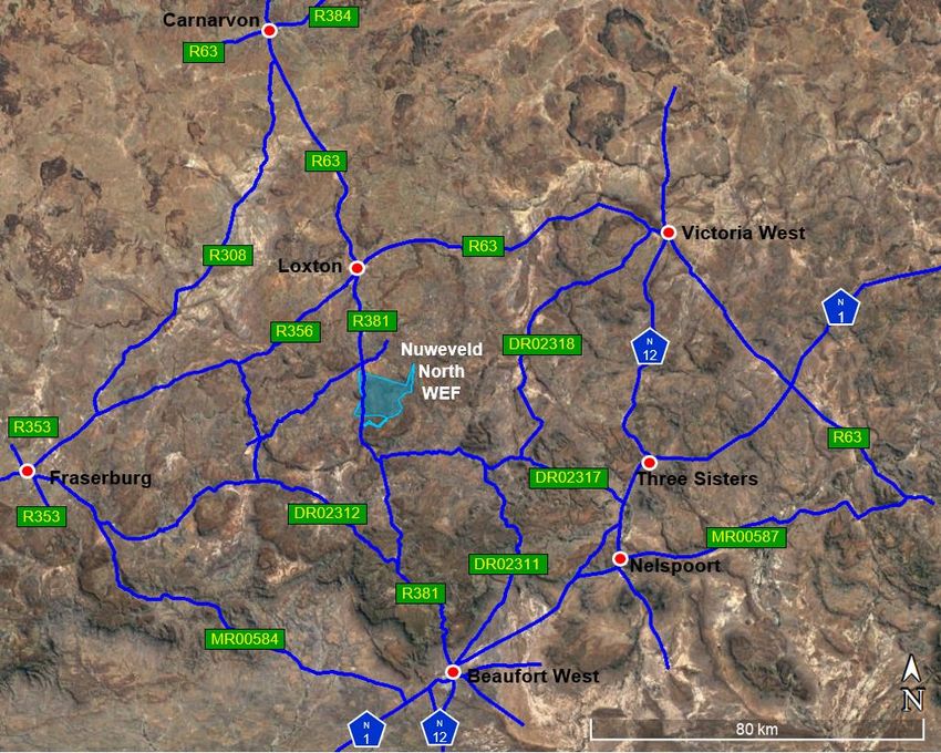
6.1 ROAD NETWORK
The existing road network, within the study area, is well developed. A combination
of national roads and first and second-order roads provides the proposed Wind Farms
and Grid Corridor accessibility to local towns and the major commercial centres within
South Africa.
In general, besides for the Molteno Pass, the De Jager's Pass and the intersection
between the R63 and R381 north of Loxton, no obvious problems were identified
associated with the transport of freight along the proposed transportation routes to
the site, nor for the possible accesses required for the construction and maintenance
of the facility. It will, however, be necessary to confirm certain aspects such as
clearances, bridge capacities, etc., by the logistics contractor as part of their
preparation as this will be dependent on the actual vehicle configuration to be used.
The more prevalent public road network, which provides access to the Nuweveld
North Wind Farm, is shown in Figure 2.
Figure 2 - Road Network
Details of the more relevant roads, within the study area, are provided below.
NUWEVELD NORTH WIND FARM - TIA (Rev 3).docx Page 106.1.1 N1 National Road
The N1 is a Principal Arterial providing high mobility between provinces, regions and
towns, and falls under the jurisdiction of the South African National Road Agency.
The N1 starts at the M6 (western Boulevard) in Cape Town and ends at Beit Bridge
Border Post at Zimbabwe border, passing through or bypassing many towns on-route.
The N1 and N12 merge approximately seven kilometres west of Beaufort West,
before splitting again at Three Sisters.
This is a Class 1 road, generally consisting of a single paved carriageway, with one
lane in each direction and paved shoulders, as shown in Figure 3. Climbing lanes
are provided along various sections of the road and there are turning lanes at major
intersections. In many cases, the shoulder is wide enough to allow yellow-line driving.
The road is in good condition with a speed limit of 120 km/h.
Figure 3 - N1 (East of Beaufort West)
6.1.2 N12 National Roads
The N12 is a Principal Arterial providing high mobility between provinces, regions and
towns, and falls under the jurisdiction of the South African National Road Agency.
The N12 starts at the N2/N9 (Kraaibosch Interchange) approximately 5 km south of
George and ends at eMalahleni, passing through or bypassing many towns on-route.
The N1 and N12 merge approximately seven kilometres west of Beaufort West,
before splitting again at Three Sisters.
This is a Class 1 road, generally consisting of a single paved carriageway, with one
lane in each direction and a combination of paved (Figure 4) and gravel shoulders.
Climbing lanes are provided along various sections of the road and there are turning
lanes at major intersections. In many cases, the shoulder is wide enough to allow
yellow-line driving. The road is in good condition with a speed limit of 120 km/h.
Figure 4 - N12 (South of Victoria West)
NUWEVELD NORTH WIND FARM - TIA (Rev 3).docx Page 116.1.3 R63 (TR016)
The R63 is a Minor Arterial providing mobility between provinces, regions and towns,
the management and maintenance of this road fall under the jurisdiction of the
Provincial Roads Department in which the roads are located. The R63 starts at the
R27 approximately 23 km east of Calvinia and ends at N2 north of East London. The
overall length of the road is split into serval sections, TR01606 represents section 6
of TR016 which lies between Carnarvon and Loxton, while TR01607 represents
section 7 of TR016 which lies between Loxton and Victoria West.
According to the Western Cape Road Information System the Functional Class of
section 9 of the R63, the road is a Class 2, with RCAM classification of R2c. The
road is situated in a 30 m wide servitude and consisting of a single paved
carriageway, 6.8 m wide, with one lane in each direction and gravel shoulders, as
shown in Figure 5. The road is in a fair condition with a speed limit of 120 km/h.
Figure 5 - R63 (East of Loxton
6.1.4 R381 (TR05801)
The R381 is a Minor Arterial providing mobility between provinces, regions and towns,
the management and maintenance of this road fall under the jurisdiction of the
Provincial Roads Department in which the roads are located. The R381 starts at the
N1, north of Beaufort West and ends at R63 in Loxton.
According to the Western Cape Road Information System, the Functional Class of
this road is a Class 2, with RCAM classification of R2b. The road is situated in a 20 m
wide servitude, sections of the road are paved, the surfacing and width details of this
road are provided in Table 4.
Table 4 - R381 Road Details
Start km End km Surface Type Width Shoulder Width Shoulder Type
0 10.07 Surfaced 7.20 2.00 Unsurfaced
10.07 13.28 Surfaced 8.60 2.00 Unsurfaced
13.28 23.80 Gravel 7.00
23.80 32.96 Surfaced 7.20 0.9 Unsurfaced
32.96 38.20 Surfaced 6.80 0.9 Unsurfaced
38.20 95.75 Gravel 8.50
95.75 111.00 Gravel
The paved sections of the R381, consists of a single paved carriageway, with one
lane in each direction and unpaved shoulders, as shown in Figure 6.
NUWEVELD NORTH WIND FARM - TIA (Rev 3).docx Page 12Figure 6 - Paved Section of R381
Several sections of the road are extremely treacherous, with no barriers and steep
drop-offs, very tight corners, negative banking and loose gravel. At kilometre stake
distance of approximately nineteen and a half, there is a bend which has an internal
radius of less than twenty-five metres and a sight distance of less than thirty metres.
A section of the road is shown in Figure 7.
Figure 7 - Unpaved Section of R381
6.1.5 DR02311
The DR02311 is an Access Collector providing access between the towns and other
roads, the management and maintenance of this road fall under the jurisdiction of the
Western Cape Provincial Roads Department. The DR02311 starts at N1 (east of
Beaufort West) and ends at the DR02317.
According to the Western Cape Road Information System, the Functional Class of
this road is a Class 4, with RCAM classification of R4a. The road is situated in a 20
m wide servitude, consisting of an 8.5 m wide gravel road, and is approximately
58.5 km long. Sections of the road, through the De Jager's Pass, are extremely
treacherous, with no barriers and steep drop-offs, as shown in Figure 8.
NUWEVELD NORTH WIND FARM - TIA (Rev 3).docx Page 13You can also read