REVISION: G Safety and Installation Instructions for SunPower AC modules
←
→
Page content transcription
If your browser does not render page correctly, please read the page content below
ENGLISH
                                                                                                                FRENCH
                                       REVISION: G

                                                                                                                GERMAN
                           Safety and Installation Instructions for
                                   SunPower AC modules
In case of inconsistencies or conflicts between the English version and any other versions of this manual (or
                document), the English version shall prevail and take control in all respects.

                                                                                                                DUTCH
      For the latest version please refer to www.sunpower.maxeon.com/int/InstallGuideACModules

                              Contents are subject to change without notice.
                                    Maxeon Solar Technologies, Ltd.
                                         sunpower.maxeon.com

                                                                                                                ITALIAN
                                                                                                                SPANISH
                                                                                                                POLISH

                                                                                                 537620 Rev.G
Table of Contents
1.0      Introduction .......................................................................................................................................................................... 3

  1.1 Definition of Terms ................................................................................................................................................................ 3

  1.2 Disclaimer Liability ................................................................................................................................................................. 3

  1.3 Certified Body Certification Information ............................................................................................................................... 3

  1.4 Limited Warranty ................................................................................................................................................................... 3

2.0      Safety Precautions ................................................................................................................................................................ 3

3.0      Electrical Characteristics ....................................................................................................................................................... 3

  3.1 Fire Rating .............................................................................................................................................................................. 3

4.0      Electrical Connections ........................................................................................................................................................... 3

  4.1 Equipment Grounding............................................................................................................................................................ 4

  4.2 Connections to AC Circuits .................................................................................................................................................... 4

  4.3 Cable Management ............................................................................................................................................................... 4

  4.4 Microinverters Connection ................................................................................................................................................... 4

5.0      Module Mounting ................................................................................................................................................................. 4

  5.1 Site Considerations ............................................................................................................................................................... 5

  5.2 Mounting Considerations...................................................................................................................................................... 6

  5.3 Handling of Modules during installations ............................................................................................................................. 6

6.0      Maintenance ......................................................................................................................................................................... 6

7.0      Troubleshooting .................................................................................................................................................................... 7

8.0      Appendix (Supplementary Technical Information) ............................................................................................................... 7

         Electrical Characteristics and Module Frame Details......................................................................................................... 7-8
ENGLISH
MAXEON SOLAR TECHNOLOGIES, LTD.
537620 Rev.G
2.0 Safety Precautions
Safety and Installation Instructions for AC Modules Before installing this device, read all safety instructions in this document.
IMPORTANT SAFETY INSTRUCTIONS
SAVE THESE INSTRUCTIONS Danger! AC Modules generate internal direct current (DC) and output
alternating current (AC); and are a source of voltage when under load and
when exposed to light. Electrical currents can arc across gaps and may
cause injury or death if improper connection or disconnection is made; or if
1.0 Introduction contact is made with module leads that are frayed or torn.
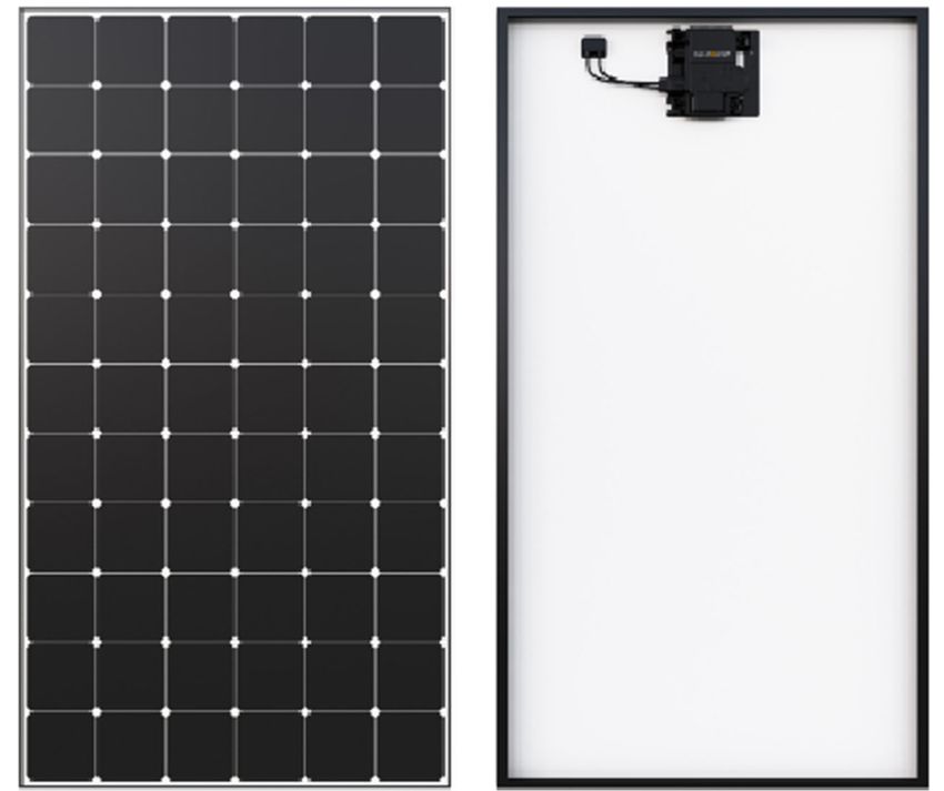
This document provides safety and installation instructions for the
SunPower AC photovoltaic (PV) modules described herein, all of which • Disconnect the AC source from all AC Modules and/or cover all modules in
bear both TUV and EnTest logos on the product label in respect to DC the PV array with an opaque cloth or material before making or breaking
and AC (Microinverter) standards: electrical connections
• Do not connect or disconnect modules when current from the modules in the
string or an external source is present
• Use only the AC locking connectors in order to defend against untrained
personnel disconnecting the modules after they have been installed.
• All installations must be performed in compliance with the applicable local
codes.
Important! Please read these instructions in their entirety before • Installation should be performed only by qualified and suitably licensed
installing, wiring, or using this product in any way. Failure to comply personnel
with these instructions will invalidate the Maxeon Solar • Remove all metallic jewelry prior to installing this product to reduce the
Technologies Limited Warranty for PV Modules and/or Enphase chance of accidental exposure to live circuits.
Energy Limited Warranty for microinverters. • Use only insulated tools to reduce your risk of electric shock.
• Do not stand on, drop, scratch, or allow objects to fall on AC Modules.
• Broken glass, J-boxes, broken connectors, and/or damaged backsheets are
1.1 Definition of Terms electrical hazards as well as laceration hazards. If a module is cracked after
AC Module: Maxeon 5, Maxeon 6, Perfomance 3 and 6 AC module installation, a qualified person should remove the module from the array and
DC Module: A typical photovoltaic solar module without microinverter unit contact the supplier for disposal instructions.
attached. • Do not install or handle modules when they are wet or during periods of high
Enphase Microinverter: Smart grid ready IQ7A, IQ8A or IQ8MC microinverter wind.
converts the DC output of the PV module into grid-compliant AC power. • Unconnected connectors must always be protected from pollution (e.g. dust,
Enphase AC cable: also called Q Cable, it is an AC cable with a length varying from humidity, foreign particles, etc.), prior to installation. Do not leave
1.3m to 2.3m depending to AC Module orientation (Portrait or Landscape), with unconnected (unprotected) connectors exposed to the environment. A clean
3.3 mm2 cross section, double insulated, outdoor rated with integrated installation environment is essential in order to avoid performance
connectors for microinverters. Maxeon Solar Technologies recommends the use degradation.
at least of 2.0m long Q cable for greater flexibility in module installation in Portrait • Do not block drain holes or allow water to pool in or near AC Module frames
configuration. AC Module plugs directly into the Q that includes factory • Contact your module supplier if maintenance is necessary.
integrated connectors. • Save these instructions!
Enphase Enlighten: Web-based monitoring and management software. Installers
can use Enlighten Manager to view detailed performance data, manage multiple
PV systems, etc. 3.0 Electrical Characteristics
DC Connector: Even if allowed by local regulation, Plug and Socket connectors Electrical characteristics and grid interaction data are shown in Table 2 and AC
mated together in a PV system must be of the same type (model, rating) from the Module datasheet. It is the installer’s responsibility to set the grid profile and to
same manufacturer i.e. a plug connector from one manufacturer and a socket check Enphase pre-configured country grid detail and this can be done with
connector from another manufacturer, or vice versa, shall not be used to make a internet access and by connecting into the Enphase Enlighten system.
connection. Approved compatible connectors: Tyco Electronics PV4S
If an installation involves a SunPower AC module which does not appear on this
1.2 Disclaimer of Liability list, please consult the product label on the back of the module or visit
The installation techniques, handling and use of this product are beyond company www.sunpower.maxeon.com for the product datasheet.
control. Therefore, Maxeon Solar Technologies does not assume responsibility for
loss, damage, or expense resulting from improper installation, handling, or use. As a reminder for DC modules: a photovoltaic module may produce more current
and/or voltage than reported at STC. Sunny, cool weather and reflection from
1.3 Certified Body Certification Information snow or water can increase current and power output. Therefore, the values of
This product intents to meet or exceed the requirements set forth by IEC 62109- Isc and Voc marked on the module should be multiplied by a factor of 1.25 when
3 for SunPower AC modules. The IEC 62109-3 Standard covers flat-plate PV determining component voltage ratings, conductor ampacities, fuse sizes, and
modules intended for installation on buildings; or those intended to be size of controls connected to PV output. An additional 1.25 multiplier may be
freestanding. The TUV certification does not include integration into a building required by certain local codes for sizing fuses and conductors. SunPower
surface because additional requirements may apply. This product is not intended recommends the use of open- circuit voltage temperature coefficients listed on
for use where artificially concentrated sunlight is applied to the module. This the datasheets when determining Maximum System Voltage.
manual shall be used in combination with industry recognized best practices and
SunPower AC modules should be installed by certified professionals only. 3.1 Fire Rating
The AC Module has the same fire rating as DC modules.
1.4 Limited Warranty
AC Module limited warranties are described in the Maxeon Solar Technologies 4.0 Electrical Connections
warranty certificates obtainable at www.sunpower.maxeon.com (Refer to the Modules must only be connected using the correct Enphase AC cable and
limited warranty document). integrated connectors. Do not alter any connectors.
©2023 Maxeon Solar Technologies, Ltd. All rights reserved. Specifications included in this document are subject to change without notice. 3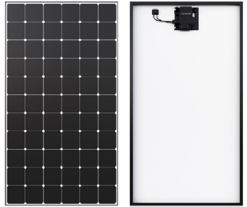
MAXEON SOLAR TECHNOLOGIES, LTD.
                                                                                                                                                               537620 Rev.G

Ensure that the cabling is not under mechanical stress (comply with bending                       Limits may vary. Refer to local requirements to define the number of
radius of ≥ 60 mm) and must not be bent on the direct exit of the connector or                    microinverters per branch in your area.
junction box. The AC Module cable system features locking connectors which,
after connected, require the use of a tool to disconnect. This defends against                        CAUTION! To reduce the risk of fire, connect only to a
untrained personnel disconnecting the modules when under load. Enphase AC
                                                                                                       circuit provided with 20 A maximum branch circuit
cable connectors are rated and tested to interrupt load current; however,
Maxeon Solar Technologies recommends that you always open the utility                                                overcurrent protection.
dedicated branch circuit breaker to remove power before plugging or unplugging
                                                                                                  Below are the major installation steps:
any connectors; install an AC isolator in accordance with local codes.
                                                                                                       1. Install the Field-wireable connector pair, optional J-Box
                                                                                                       2. Position the Enphase Q Cable
4.1 Equipment Grounding                                                                                Per module:
Module grounding is required as per IEC 60364-7-712 and where deemed
                                                                                                                 3      Position AC module and pop-out microinverters. Refer to
mandatory within the local regulatory framework. The purpose of the module
                                                                                                                        Section 5.3 for illustation
grounding is both for protection and functional reasons. The functional aspect of
                                                                                                                 4      Connect microinverters to Q Cable connector
this requirement is to enable the Inverter or power conditioning device to provide
                                                                                                                 5      Install AC Modules
earth fault detection and any alarm indication. Maxeon Solar Technologies
                                                                                                                 6      Manage Q cable to module frame and rail
recommends using one of the following methods of grounding the module frame.
                                                                                                       Per row:
In addition, to avoid corrosion due to dissimilar metal interfaces, Maxeon Solar
                                                                                                                 7      Create installation map
Technologies recommends stainless steel hardware between copper and
                                                                                                                 8. Terminate Q cable at last microinverter
aluminum. Testing should be done to validate grounding with temperature, salt
                                                                                                                 9. Connect to J-Box
environment and high current.
                                                                                                                 10. Energize system
1)   Grounding using specified grounding holes: Use the mounting frame
     provisioned grounding holes for connecting the module to the racking with
                                                                                                  4.3 Cable Management
     a suitably sized earthing conductor.
                                                                                                  Use cable clips or cable ties wraps to attach the AC cable to the racking. The cable
2)   Grounding with clamp / claw: Clamp or claw can be installed between the                      must be supported to avoid any cable
     module and racking system. Align a grounding clamp to the frame hole, and                    undue sag as per local requirement.
     place a grounding bolt through the grounding clamp and frame. Ensure the
     clamp used when is fastened, will effectively pierce the anodized coating of                 For Performance 3 AC modules, be careful
     the module and ensure suitable conductivity.                                                 to not unplug the DC cable premounted in
                                                                                                  factory into specific cable supports.
3)   Modules may be grounded by attaching a lay-in lug to one of the grounding                    Dress any excess cabling in loops so that it
     holes on the module frame, and attach the ground conductor to the lug. Use                   does not contact the roof. Do not form
     stainless steel hardware (bolt, washers, and nut). Use an external-tooth star                loops smaller than 12 cm in diameter.
     washer between the lug and the module frame in order to pierce the
     anodizing and establish electrical contact with the aluminum frame. The
     assembly must end with a nut that’s torqued to 2.3-2.8 Nm (for a M4 bolt).
     A lock washer or other locking mechanism is required to maintain tension                     4.4 Microinverters Connection
     between the bolt and the assembly. The conductor must be attached to the                     Refer to the major installation steps defined in Section4.2and listen for a click:
     ground lug using the lug’s set screw.                                                        1) when the microinverters are pop out and
4)   Modules may be grounded using a ground clip or ground washer or as part                      2) when AC connectors engage
     of a module clamp. These grounding clips/washers must be able to                             Inspect the AC connectors to ensure that
     effectively pierce the anodized coating of the module frame and establish                    they are not broken, misshapen, or
     suitable electrical conductivity.                                                            otherwise degraded prior to connection.
                                                                                                  Cover any unused connectors on the AC
All above solutions are possible but should be tested with the mounting structure                 cable with Enphase Sealing Caps. Listen for
for grounding purpose.                                                                            a click as the sealing caps engage.
4.2 Connection to AC Circuits
It is the installer’s responsibility to verify grid compatibility in your installation
region (240/380 or 4-wire 2-pole). The AC Modules must be connected to a utility
source at the correct voltage and frequency in order to operate and produce                       CAUTION! Install sealing caps on all unused AC connectors
power. They are not standalone generators and do not create AC voltage thus are                     as these connectors become live when the system is
not capable of operation independent of a utility-generated AC signal. The AC
                                                                                                  energized. Sealing caps are required for protection against
Modules must be connected only to a dedicated branch circuit. The AC cables and
connectors are certified and rated for the maximum number of AC units in parallel                                      moisture ingress.
only. When connecting modules, DO NOT exceed the following single AC branch
circuit maximum number of modules.                                                                5.0 Module Mounting
The maximum number of microinverters that can be installed on each AC branch
circuit can be found in the Product's datasheet. This circuit must be protected by                This section contains information for AC Modules. Ensure that you use the correct
overcurrent protection. Plan your AC branch circuits to meet the following limits                 information for your module type.
for maximum number of AC Module per branch when protected with a 20 amp                           The Maxeon Solar Technologies Limited Warranty for PV Modules is contingent
(maximum) over current protection device.                                                         upon modules being mounted in accordance with the requirements described in
                                                                                                  this section.
 Maximum* IQ Micros per AC            Maximum* IQ Micros per AC
 branch circuit (240 VAC)             branch circuit (230 VAC)                                    5.1 Site Considerations
 Region: EU                           Region: APAC                                                AC Module should only be mounted in locations that meet the following
 IQ7A or IQ8A: 10                     IQ7A: 11                                                    requirements:
 IQ8MC: 11

                 ©2023 Maxeon Solar Technologies, Ltd. All rights reserved. Specifications included in this document are subject to change without notice.                             4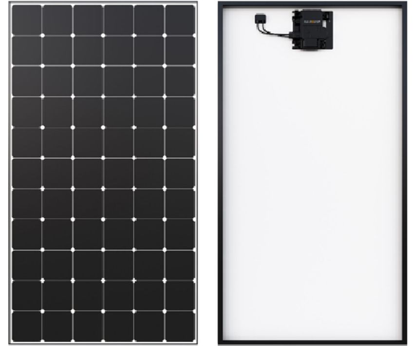
MAXEON SOLAR TECHNOLOGIES, LTD.
                                                                                                                                                              537620 Rev.G

Maximum Altitude: AC Modules can be installed in locations with a maximum
of 2000 meter above sea level.                                                                   When installed on a roof, the module shall be mounted according to the local and
                                                                                                 regional building and fire safety regulations. In case the module is installed in a
Operating Temperature: AC Modules must be mounted in environments that                           roof integrated PV-System (BIPV), it shall be mounted over a watertight and fire-
ensure that the modules will operate within the following maximum and                            resistant underlayment rated for such application.
minimum temperatures:
   Max. Operating Cell Temp.                +85°C                                                For Peformance 3 and 6 AC modules, in order to provide better access of
   Max. Operating microinverter Temp.       + 60°C                                               connection for AC cables into the microinverter, Maxeon recommends the
   Max. AC Module Ambient Temp.             +50°C                                                following installation sequence:
   Min. AC Module Operating Temp.           −40°C                                                      •     When the microinverter is in lower position, then it is recommended
                                                                                                             to install the modules from Left to Right.
Design Strength: AC Modules are designed to meet a maximum positive (or                                •     When the microinverter is in upper position, then it is recommended
upward, e.g. wind) and negative (or downward, e.g. static load) design pressure                              to install the modules from Right to Left.
when mounted in the mounting configurations specified in Appendix for the
details on load ratings and mounting locations. AC Modules have also been                        Modules mounting systems should only be installed on building that have been
evaluated to IEC 61215 for a positive or negative design load of 3600 Pa with a                  formally considered for structural integrity and confirmed to be capable of
1.5 Safety Factor.                                                                               handling the additional weighted load of the modules and mounting systems, by
                                                                                                 a certified building specialist or engineer.
When mounting modules in snow-prone or high-wind environments, special care
should be taken to mount the modules in a manner that provides sufficient design                 AC Modules are only certified for use when their factory frames are fully intact.
strength while meeting local code requirements.                                                  Do not remove or alter any module frame. Creating additional mounting holes
                                                                                                 may damage the module and reduce the strength of the frame.
Important! Refer to Appendix that show where to mount in module frame and
the allowable load ratings corresponding to the mounting zones chosen. To use                    Modules may be mounted using the following methods only:
the tables, identify the two mounting zones in which you wish to mount. You may                  1) Pressure Clamps or Clips:           Force must not deform
choose to mount at any location as long as the mounting points are symmetric                         Mount the module with              top frame flange or
about one axis of the module. Identify the combination of mounting zones you                         the clips attached to the          glass may break              Force has
have chosen in the Appendix and then refer to the corresponding load rating.                         longer sides of the module.                                     to be
                                                                                                                                                                     applied in
Note also that load ratings are different for modules supported by rails; versus                     Refer to the allowable
                                                                                                                                                                     line with
systems that attach modules underneath the module frame or without rail                              ranges in Section 5.0                                           frame
support.                                                                                             (Appendix). Installers must                                     wall
                                                                                                     ensure the clamps are of
Additional Authorized Operating Environments:                                                        sufficient strength to allow
                                                                                                                                            Figure 1a: Clamp Force Locations
Modules can be mounted in the following aggressive environment according to                          for the maximum design
the test limits mentioned below:                                                                     pressure of the module. Clips and clamps are not provided by Maxeon Solar
Salt mist corrosion testing: IEC 61701 Severity 6                                                    Technologies. Clamps that secure to the top of the frame must not deform
Ammonia Corrosion Resistance: IEC 62716 Concentration: 6,667 ppm                                     the top flange. Clamps must apply force collinear with the ‘wall’ of the
                                                                                                     module frame and not only to the top flange. Clamps shall not apply
Excluded Operating Environments                                                                      excessive force to the frame, warp the top flange, or contact the glass -
Certain operating environments are not recommended for SunPower AC                                   these practices void the module warranty and risk frame and glass
modules, and are excluded from the Maxeon Solar Technologies Limited                                 breakage. Figure 1a illustrates locations for top frame clamp force. Avoid
Warranty for these modules. Maxeon’s modules should not be mounted a site                            clamping within 50mm of module corners to reduce risk of frame corner
where it may be subject to direct contact with salt water, or other aggressive                       deflection and glass breakage. When clamping to the module frame, torque
environment. Maxeon’s modules should not be installed near flammable liquids,                        shall never exceed 15 N.m to reduce chances of frame deformation. A
gases, or locations with hazardous materials; or moving vehicles of any type.                        calibrated torque wrench must be used. Mounting systems should be
Contact Maxeon Solar Technologies if there are any unanswered questions                              evaluated for compatibility before installing specially when the system is
concerning the operating environment.                                                                not using Clamps or clips. Please contact Maxeon Solar Technologies for the
                                                                                                     approval of the use of non-standard pressure clamps or clips where torque
5.2 Mounting Configurations                                                                          values are higher than otherwise stated.
Modules may be mounted at, appropriate orientation to maximize sunlight
exposure.                                                                                              Minimum clamp width allowance is ≥35mm, and for corner clamping the
In order to prevent water from entering the junction box (which could present a                        minimum clamp width is: ≥50mm. Clamps should not be in contact with the
safety hazard), modules should be oriented such that the junction box is in the                        front glass and clamps should not deform the frame.
uppermost position and should not be mounted such that the top surface faces
downward.                                                                                              Maxeon does not recommend nor endorse the application on the modules
In addition, ensure the module orientation also prevents the microinverter from                        of clamps which, as part of their grounding or earthing function, have teeth
direct exposure to rain, UV and other harmful weather events (ice/snow).                               or claw features (see Figure 2) which may, individually or cumulatively,
We also want to remind that the watertightness is not ensured by the modules                           cause the module breakage due to (and without limitation):
but by the mounting system and that drainage should be well designed for AC
modules. Maxeon recommends for a good performance of the system (reduction                             i)    the grounding features touching the
of soiling effect/water pooling) a minimum of 5° tilt angle.                                           front glass which is incorporated into the
Clearance between the module frames and structure or ground is required to                             module due to the position of such
prevent wiring damage and allows air to circulate behind the module. The                               grounding feature,
recommended assembling clearance between each module installed on any                                  ii) the shape, the position or the number
mounting system is a minimum of 5 mm distance.                                                         of the grounding features deforming the
                                                                                                       module top frame, or
Clearance between the module frame and roof surface is required to prevent                             iii) the clamp being over-torqued during                   Figure 2
wiring damage and to enable air to circulate behind the module. Therefore a                            the installation.
minimum of 50mm is required between the module frame and the roof surface.

                ©2023 Maxeon Solar Technologies, Ltd. All rights reserved. Specifications included in this document are subject to change without notice.                            5
MAXEON SOLAR TECHNOLOGIES, LTD.
                                                                                                                                                               537620 Rev.G

2)   End Mount: End mounting is clipping/clamping of solar modules at the                         a soft cloth or sponge and water after wetting. NEVER use harsh cleaning
     corner of short side to the supporting rail. The end-mounting rail and clips                 materials such as scouring powder, steel wool, scrapers, blades, or other sharp
     or clamps must be of sufficient strength to allow for the maximum design                     instruments to clean module glass. Use of such materials on the modules will void
     pressure of the module. Verify this capacity for both 1) clamps or clips and                 the product warranty.
     2) end mounting system vendor before installation.
                                                                                                  7.0 Troubleshooting
5.3 Handling of Modules during Installation                                                       Make sure to follow all safety precautions described in this installation manual.
                                                                                                  The microinverters are monitored by Enphase Enlighten system. If a module is
Never lift or move the modules using cables or the junction box under any                         found to not produce power through the Enphase Enlighten System, please
circumstances. Do not place modules face forward in direct contact with abrasive                  contact Enphase as the first point in the trouble shooting process. If Enphase
surfaces such as roofs, driveways, wooden pallets, railings, or walls etc. The front              microinverter is found to be functioning properly, Enphase will contact Maxeon
surface of a module is sensitive to oils and abrasive surfaces, which may lead to                 Technical Support directly.
scratches and irregular soiling.                                                                  Troubleshooting an inoperative microinverter, please follow the Enphase
                                                                                                  troubleshooting process:
Be careful not to touch the micro-inverter while unloading the Performance 3 AC                   1. Web forms – send an email through https://enphase.com/en-
modules, as the micro-inverter height exceeds the module frame slightly.                          in/support/contact-support#form

                                                                                                  2. Call center
Shipping Position: X = 31.7mm                                                                     Europe
                                                                                                  Netherlands: +31-73-7041633
                                                                                                  France/Belgium: +33(0)484350555
                                                                                                  Germany: +49 761 887893-20
                                                                                                  UK: +44 (0)1908 828928
                                                                                                  APAC
Install Position: X = 46.7mm                                                                      Melbourne, Australia: +1800 006 374
                                                                                                  New Zealand: +09 887 0421
                                                                                                  India: +91-80-6117-2500

                                                                                                  3. Claiming process through Enlighten for installers:
                                                                                                  https://enphase.com/en-uk/support/system-owners/troubleshooting

                                                                                                  All other faults please refer to the Enphase IQ Envoy Installation and Operation
                                                                                                  Manual at enphase.com/support for troubleshooting procedures.
AC Modules are featured with antireflective coated glass and they are prone to
visible finger print marks if touched on the front glass surface. Maxeon Solar
Technologies recommends handing AC Modules with gloves (no leather gloves)                        8.0 Appendix (Supplementary Technical Information)
or limiting touching of the front surface. Any finger print marks resulting from
installation will naturally disappear over time or can be reduced by following the                1. Enphase IQ7/IQ8A/ IQ8MC Installation and Operation Manual
washing guidelines in Section 6.0 below. Any module coverage (colored plastic                     Please refer to local installation guide on Enphase website, for instance,
tarps or similar) during installation can lead to permanent front glass                           https://enphase.com/en-uk/support/enphase-iq-7-iq-7-iq-7x-microinverter-
discoloration and is not recommended. The use of vacuum lifting pads can cause                    installation-and-operation-manual
permanent marks on the front glass.
                                                                                                  2. Enphase Installer Toolkit Commissioning:
Shading incidence need to be avoided during PV system operation. The system is
                                                                                                  https://enphase.com/en-in/support/gettingstarted/commission
not supposed to be energized until the mounting scaffolding or railing have been
removed from the roof.
                                                                                                  Enphase Installer Toolkit is the mobile app where you can view the
                                                                                                  microinverter serial numbers and connect to the IQ Envoy to track system
Systems should be disconnected in any cases of maintenance which can cause
                                                                                                  installation progress. To download, go to http://www.enphase.com/toolkit and
shading (e.g. chimney sweeping, any roof maintenance, antenna/dish
                                                                                                  log in to your Enlighten account.
installations, etc.).
                                                                                                  Getting Started Guide:
                                                                                                  https://enphase.com/sites/default/files/GettingStartedGuide_SystemVerificatio
6.0 Maintenance                                                                                   nUsingInstallerToolkit_InsideSystem.pdf
Maxeon Solar Technologies recommends visual inspection on a regular basis of
AC modules for safe electrical connections, sound mechanical connection, and                      Installation Troubleshooting :
free from corrosion. This visual inspection should be performed by trained and                    https://enphase.com/en-uk/support-associated-products/installer-
licensed personnel. The standard frequency is once a year according to                            toolkit
environmental conditions.
                                                                                                  3. Enphase IQ Envoy Installation and Operation Manual:
Periodic cleaning of AC Modules is recommended, but is not required. Periodic                     Refer to the Enphase IQ Envoy Installation and Operation Manual to activate the
cleaning has resulted in improved module performance, especially in regions with                  system monitoring and grid management functions.
low levels of annual precipitation (less than 46,3cm (18,25 inches)). Consult                     https://enphase.com/sites/default/files/downloads/support/IQ-Envoy-Manual-
installer supplier about recommended cleaning schedules for your area. Do not                     EN-US.pdf
clean or spray modules with water during normal operation (module glass surface
is hot). To clean a module, spray it with potable, non-heated water. Normal water                 The guide provides the following:
pressure is more than adequate, but pressurized water 100 bar (min 50 cm                          o    Connecting the Envoy
distance) may be used. Fingerprints, stains, or accumulations of dirt on the front                o    Detecting devices and scanning the installation map
surface of the module may be removed as follows: rinse the area and wait 5                        o    Connecting to Enlighten and registering the system
minutes. Re-wet the area and then use a soft sponge or seamless cloth to wipe
the glass surface in a circular motion. Fingerprints typically can be removed with

                 ©2023 Maxeon Solar Technologies, Ltd. All rights reserved. Specifications included in this document are subject to change without notice.                           6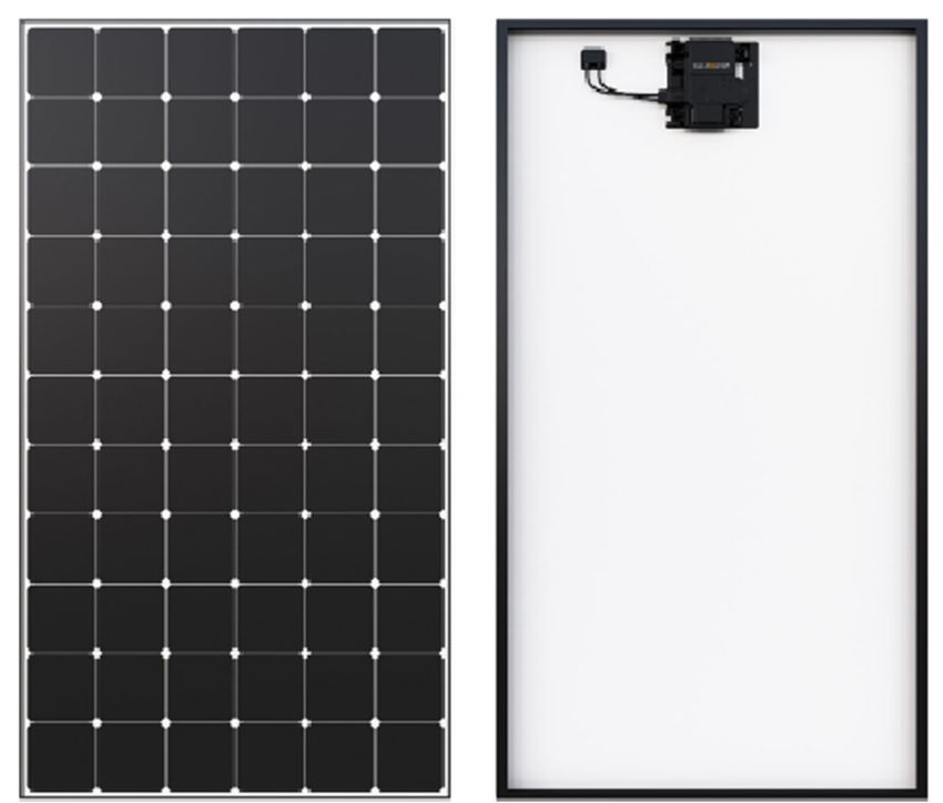
MAXEON SOLAR TECHNOLOGIES, LTD.
537620 Rev.G
Table 2. Electrical Characteristics and Grid Interaction.
DC Electrical Characteristics:
DC Ratings
DC values @ STC Temperature Efficiency
Curr. at Voltage
Voltage at Open Circuit Curr. (Isc) Power Temp. NOCT @ Nom. Peak power
Nom. Power Rated Short Circuit (Voc) Temp. Module
Model Rated Power Voltage, Voc Temp. Coeff. Coeff. 20°C (value ± (W) per unit area:
Power (W) Tol. (%) Power, Impp Curr., Isc(A) Coeff. Efficiency (%)
(Vmpp) (V) (%/°C) (%/°C) 2°C) m2 / ft2
(A) (%/°C)
SPR-MAX6-440-E4-AC 440 +5/−0 40.5 10.87 48.2 11.58 0.057 −0.239 −0.29 47.1 22.8 228/21.2
SPR-MAX6-435-E4-AC 435 +5/−0 40.3 10.82 48.2 11.57 0.057 −0.239 −0.29 47.1 22.5 225/20.9
SPR-MAX6-425-E4-AC 425 +5/−0 39.8 10.68 48.1 11.55 0.057 −0.239 −0.29 47.1 22.0 220/20.4
SPR-MAX6-420-E4-AC 420 +5/−0 39.6 10.62 48.1 11.53 0.057 −0.239 −0.29 47.1 21.7 217/20.2
SPR-MAX6-425-BLK-E4-AC 425 +5/−0 40.3 10.58 48.2 11.32 0.057 −0.239 −0.29 46.9 22.0 220/20.4
SPR-MAX6-415-BLK-E4-AC 415 +5/−0 39.8 10.43 48.1 11.29 0.057 −0.239 −0.29 46.9 21.5 215/20.0
SPR-MAX6-410-BLK-E4-AC 410 +5/−0 39.5 10.37 48.1 11.28 0.057 −0.239 −0.29 46.9 21.2 212/19.7
SPR-MAX6-450-E3-AC 450 +5/−0 41.0 10.99 48.3 11.61 0.057 −0.239 −0.29 47.1 23.3 233/21.6
SPR-MAX6-445-E3-AC 445 +5/−0 40.7 10.93 48.2 11.60 0.057 −0.239 −0.29 47.1 23.0 230/21.4
SPR-MAX6-440-E3-AC 440 +5/−0 40.5 10.87 48.2 11.58 0.057 −0.239 −0.29 47.1 22.8 228/21.2
SPR-MAX6-435-E3-AC 435 +5/−0 40.3 10.82 48.2 11.57 0.057 −0.239 −0.29 47.1 22.5 225/20.9
SPR-MAX6-430-E3-AC 430 +5/−0 40.0 10.74 48.2 11.56 0.057 −0.239 −0.29 47.1 22.3 223/20.7
SPR-MAX6-425-E3-AC 425 +5/−0 39.8 10.68 48.1 11.55 0.057 −0.239 −0.29 47.1 22.0 220/20.4
SPR-MAX6-420-E3-AC 420 +5/−0 39.6 10.62 48.1 11.53 0.057 −0.239 −0.29 47.1 21.7 217/20.2
SPR-MAX6-430-BLK-E3-AC 430 +5/−0 40.5 10.62 48.2 11.33 0.057 −0.239 −0.29 46.9 22.3 223/20.7
SPR-MAX6-425-BLK-E3-AC 425 +5/−0 40.3 10.58 48.2 11.32 0.057 −0.239 −0.29 46.9 22.0 220/20.4
SPR-MAX6-420-BLK-E3-AC 420 +5/−0 40.0 10.49 48.2 11.30 0.057 −0.239 −0.29 46.9 21.7 217/20.2
SPR-MAX6-415-BLK-E3-AC 415 +5/−0 39.8 10.43 48.1 11.29 0.057 −0.239 −0.29 46.9 21.5 215/20.0
SPR-MAX6-410-BLK-E3-AC 410 +5/−0 39.5 10.37 48.1 11.28 0.057 −0.239 −0.29 46.9 21.2 212/19.7
SPR-MAX6-405-BLK-E3-AC 405 +5/−0 39.3 10.30 48.1 11.26 0.057 −0.239 −0.29 46.9 21.0 210/19.5
SPR-MAX6-400-BLK-E3-AC 400 +5/−0 39.1 10.24 48.0 11.25 0.057 −0.239 −0.29 46.9 20.7 207/19.2
SPR-MAX5-420-E3-AC 420 +5/−0 40.5 10.4 48.2 10.9 0.057 −0.239 −0.29 43 22.5 225/20.9
SPR-MAX5-415-E3-AC 415 +5/−0 40.3 10.3 48.2 10.9 0.057 −0.239 −0.29 43 22.3 221/20.5
SPR-MAX5-410-E3-AC 410 +5/−0 40.0 10.2 48.2 10.9 0.057 −0.239 −0.29 43 22.0 220/20.4
SPR-MAX5-400-E3-AC 400 +5/−0 39.5 10.1 48.1 10.9 0.057 −0.239 −0.29 43 21.5 212/19.7
SPR-MAX5-390-E3-AC 390 +5/−0 39.0 9.99 48.0 10.8 0.057 −0.239 −0.29 43 20.9 209/19.4
SPR-P6-415-BLK-E9-AC 415 +3/−0 30.2 13.76 36.7 14.39 0.04 −0.27 −0.34 45 21.1 211/19.6
SPR-P6-410-BLK-E9-AC 410 +3/−0 29.9 13.73 36.4 14.38 0.04 −0.27 −0.34 45 20.9 209/19.4
SPR-P6-405-BLK-E9-AC 405 +3/−0 29.6 13.70 36.2 14.37 0.04 −0.27 −0.34 45 20.6 206/19.2
SPR-P6-415-BLK-E8-AC 415 +3/−0 30.2 13.76 36.7 14.39 0.04 −0.27 −0.34 45 21.1 211/19.6
SPR-P6-410-BLK-E8-AC 410 +3/−0 29.9 13.73 36.4 14.38 0.04 −0.27 −0.34 45 20.9 209/19.4
SPR-P6-405-BLK-E8-AC 405 +3/−0 29.6 13.70 36.2 14.37 0.04 −0.27 −0.34 45 20.6 206/19.2
SPR-P3-385-BLK-E4-AC 385 +5/−0 36.3 10.61 43.7 11.31 0.06 −0.28 −0.34 45 19.6 196/17.3
SPR-P3-380-BLK-E4-AC 380 +5/−0 35.9 10.59 43.4 11.28 0.06 −0.28 −0.34 45 19.4 194/17.1
SPR-P3-375-BLK-E4-AC 375 +5/−0 35.5 10.57 43.0 11.26 0.06 −0.28 −0.34 45 19.1 191/16.9
SPR-P3-370-BLK-E4-AC 370 +5/−0 35.1 10.55 42.6 11.24 0.06 −0.28 −0.34 45 18.9 189/16.7
SPR-P3-385-BLK-E3-AC 385 +5/−0 36.3 10.61 43.7 11.31 0.06 −0.28 −0.34 45 19.6 196/17.3
SPR-P3-380-BLK-E3-AC 380 +5/−0 35.9 10.59 43.4 11.28 0.06 −0.28 −0.34 45 19.4 194/17.1
SPR-P3-375-BLK-E3-AC 375 +5/−0 35.5 10.57 43.0 11.26 0.06 −0.28 −0.34 45 19.1 191/16.9
SPR-P3-370-BLK-E3-AC 370 +5/−0 35.1 10.55 42.6 11.24 0.06 −0.28 −0.34 45 18.9 189/16.7
©2023 Maxeon Solar Technologies, Ltd. All rights reserved. Specifications included in this document are subject to change without notice. 7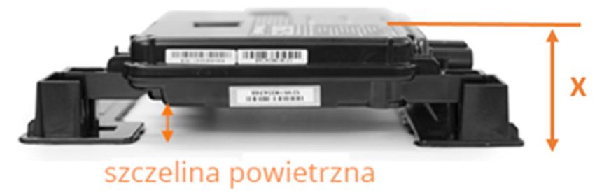
MAXEON SOLAR TECHNOLOGIES, LTD.
537620 Rev.G
AC Electrical Characteristics:
AC Ratings
AC values @ STC
Operating Limits
AC Max. Extended AC Short Circuit
AC Max. Max. AC Peak AC Port
AC Voltage Cont. Frequency Fault Current Overvolta Power Power Factor
Cont. Series Output Freq. (nom., Backfeed Max. Units per Branch
Model Output Output Range Over 3 Cycles ge Class Factor (adjustable)
Output Fuse Power Hz) Current (Europe – Australia)
(nom., V) Power, W (Hz) (A rms) AC Port Setting lead. / lag.
Curr. (A) (A) (W) or VA (mA)
or VA
SPR-MAX6-440-E4-AC 219-264 1.52 20 349 366 50 45-55 5.8 III 18 1.0 0.8 / 0.8 10 - 11
SPR-MAX6-435-E4-AC 219-264 1.52 20 349 366 50 45-55 5.8 III 18 1.0 0.8 / 0.8 10 - 11
SPR-MAX6-425-E4-AC 219-264 1.52 20 349 366 50 45-55 5.8 III 18 1.0 0.8 / 0.8 10 - 11
SPR-MAX6-420-E4-AC 219-264 1.52 20 349 366 50 45-55 5.8 III 18 1.0 0.8 / 0.8 10 - 11
SPR-MAX6-425-BLK-E4-AC 219-264 1.52 20 349 366 50 45-55 5.8 III 18 1.0 0.8 / 0.8 10 - 11
SPR-MAX6-415-BLK-E4-AC 219-264 1.52 20 349 366 50 45-55 5.8 III 18 1.0 0.8 / 0.8 10 - 11
SPR-MAX6-410-BLK-E4-AC 219-264 1.52 20 349 366 50 45-55 5.8 III 18 1.0 0.8 / 0.8 10 - 11
SPR-MAX6-450-E3-AC 219-264 1.52 20 349 366 50 45-55 5.8 III 18 1.0 0.8 / 0.8 10 - 11
SPR-MAX6-445-E3-AC 219-264 1.52 20 349 366 50 45-55 5.8 III 18 1.0 0.8 / 0.8 10 - 11
SPR-MAX6-440-E3-AC 219-264 1.52 20 349 366 50 45-55 5.8 III 18 1.0 0.8 / 0.8 10 - 11
SPR-MAX6-435-E3-AC 219-264 1.52 20 349 366 50 45-55 5.8 III 18 1.0 0.8 / 0.8 10 - 11
SPR-MAX6-430-E3-AC 219-264 1.52 20 349 366 50 45-55 5.8 III 18 1.0 0.8 / 0.8 10 - 11
SPR-MAX6-425-E3-AC 219-264 1.52 20 349 366 50 45-55 5.8 III 18 1.0 0.8 / 0.8 10 - 11
SPR-MAX6-420-E3-AC 219-264 1.52 20 349 366 50 45-55 5.8 III 18 1.0 0.8 / 0.8 10 - 11
SPR-MAX6-430-BLK-E3-AC 219-264 1.52 20 349 366 50 45-55 5.8 III 18 1.0 0.8 / 0.8 10 - 11
SPR-MAX6-425-BLK-E3-AC 219-264 1.52 20 349 366 50 45-55 5.8 III 18 1.0 0.8 / 0.8 10 - 11
SPR-MAX6-420-BLK-E3-AC 219-264 1.52 20 349 366 50 45-55 5.8 III 18 1.0 0.8 / 0.8 10 - 11
SPR-MAX6-415-BLK-E3-AC 219-264 1.52 20 349 366 50 45-55 5.8 III 18 1.0 0.8 / 0.8 10 - 11
SPR-MAX6-410-BLK-E3-AC 219-264 1.52 20 349 366 50 45-55 5.8 III 18 1.0 0.8 / 0.8 10 - 11
SPR-MAX6-405-BLK-E3-AC 219-264 1.52 20 349 366 50 45-55 5.8 III 18 1.0 0.8 / 0.8 10 - 11
SPR-MAX6-400-BLK-E3-AC 219-264 1.52 20 349 366 50 45-55 5.8 III 18 1.0 0.8 / 0.8 10 - 11
SPR-MAX5-420-E3-AC 219-264 1.52 20 349 366 50 45-55 5.8 III 18 1.0 0.8 / 0.8 10 - 11
SPR-MAX5-415-E3-AC 219-264 1.52 20 349 366 50 45-55 5.8 III 18 1.0 0.8 / 0.8 10 - 11
SPR-MAX5-410-E3-AC 219-264 1.52 20 349 366 50 45-55 5.8 III 18 1.0 0.8 / 0.8 10 -11
SPR-MAX5-400-E3-AC 219-264 1.52 20 349 366 50 45-55 5.8 III 18 1.0 0.8 / 0.8 10 - 11
SPR-MAX5-390-E3-AC 219-264 1.52 20 349 366 50 45-55 5.8 III 18 1.0 0.8 / 0.8 10 - 11
SPR-P6-415-BLK-E9-AC 184-276 1.43 20 325 330 50 45-55 - III - 1.0 0.8 / 0.8 11 – N/A
SPR-P6-410-BLK-E9-AC 184-276 1.43 20 325 330 50 45-55 - III - 1.0 0.8 / 0.8 11 – N/A
SPR-P6-405-BLK-E9-AC 184-276 1.43 20 325 330 50 45-55 - III - 1.0 0.8 / 0.8 11 – N/A
SPR-P6-415-BLK-E8-AC 184-276 1.59 20 360 366 50 45-55 - III - 1.0 0.8 / 0.8 10 – N/A
SPR-P6-410-BLK-E8-AC 184-276 1.59 20 360 366 50 45-55 - III - 1.0 0.8 / 0.8 10 – N/A
SPR-P6-405-BLK-E8-AC 184-276 1.59 20 360 366 50 45-55 - III - 1.0 0.8 / 0.8 10 – N/A
SPR-P3-385-BLK-E4-AC 219-264 1.52 20 349 366 50 45-55 5.8 III 18 1.0 0.8 / 0.8 10 -11
SPR-P3-380-BLK-E4-AC 219-264 1.52 20 349 366 50 45-55 5.8 III 18 1.0 0.8 / 0.8 10 - 11
SPR-P3-375-BLK-E4-AC 219-264 1.52 20 349 366 50 45-55 5.8 III 18 1.0 0.8 / 0.8 10 - 11
SPR-P3-370-BLK-E4-AC 219-264 1.52 20 349 366 50 45-55 5.8 III 18 1.0 0.8 / 0.8 10 - 11
SPR-P3-385-BLK-E3-AC 219-264 1.52 20 349 366 50 45-55 5.8 III 18 1.0 0.8 / 0.8 10 -11
SPR-P3-380-BLK-E3-AC 219-264 1.52 20 349 366 50 45-55 5.8 III 18 1.0 0.8 / 0.8 10 - 11
SPR-P3-375-BLK-E3-AC 219-264 1.52 20 349 366 50 45-55 5.8 III 18 1.0 0.8 / 0.8 10 - 11
SPR-P3-370-BLK-E3-AC 219-264 1.52 20 349 366 50 45-55 5.8 III 18 1.0 0.8 / 0.8 10 - 11
Please refer to the module datasheet for the AC electrical characteristics
©2023 Maxeon Solar Technologies, Ltd. All rights reserved. Specifications included in this document are subject to change without notice. 8
MAXEON SOLAR TECHNOLOGIES, LTD.
                                                                                                                                                                                                     537620 Rev.G

APPENDIX: MOUNTING CONFIGURATIONS AND LOAD RATINGS

    SunPower Maxeon 5 AC Residenal Solar Panel
    (SPR-MAX5-XXX-BLK-E3-AC)
                                      0                                                                                                                                                        0

                                               150       265                              514                  714               714                514                  265        150

                                                                                                                                                                                                              0
                                                       363.7 mm                    Microinverter
                                                                                   Exclusion Zone

                                                                                                                                                                                                        350
                                            252.8 mm
                     1017 mm

                                                                                                                                                                                                        350
                                                                                                                                                                                          A

                                                                                                                                                                                                              0
                                                                                                              1835 mm
                                                                    Measurement Tolerances are +/-3mm for the Length and Width of the module.
                                                                                           A - Ground Holes (4X Ø 4.2mm)

    TOP CLAMPS
          Mounng             Mounng Configuraon Diagram         Mounng Zone
                                                                                                Test Load     Design Load
         Configuraon                                                Locaons
                                                                  (distance from corner    Downward/Upward    Downward/Upward
                                                                                                                                                                  GEN 5.2 FRAME PROFILE
          Descripon          Front View       Back View                                       (Pa)               (Pa)
                                                                       in mm)

                                                                                                                                                    SIDE FRAME PROFILE                        END FRAME PROFILE
     Long Side Mounng,                                              265 - 514             +5400/-4050       +3600/-2700
     Rails Perpendincular
      to Mounng Frame
                                                                     514 - 714             +2400/-2550        +1600/-1700
                                                                                                                                                 40 mm                                    40 mm
                                                                      0 - 150               +2400/-2400        +1600/-1600
                                                                     150 - 265              +2400/-2400       +1600/-1600
      Long Side Mounng,
        Point Supported                                              265 - 514              +5400/-3600       +3600/-2400
                                                                                                                                                                  32 mm                                   24 mm
                                                                     514- 714               +2400/-2400       +1600/-1600

                                                                      0 - 150              +2400/-2400        +1600/-1600
      Long Side Mounng,                                             150 - 265                                +1600/-1600
                                                                                            +2400/-2400
        Rails Parallel to
        Mounng Frame                                                265 - 514              +5400/-3600       +3600/-2400
                                                                     514- 714              +2400/-2400        +1600/-1600

     Short Side Mounng,
     Rails Perpendicular to                                            0 - 350              +3600/-2400       +2400/-1600
        Mounng Frame
          (End Mount)

     Short Side Mounng,
       Point Supported                                                0 - 350               +2400/-2400       +1600/-1600
         (End Mount)

     Short Side Mounng,
       Rails Parallel to
       Mounng Frame                                                   0 - 350              +2400/-2400       +1600/-1600
         (End Mount)

    1 Design Load considers 1.5 Factor of Safety, Test load = Design load x 1.5. Product Warranty covers only design            4 In the cases where hybrid mounng is necessary (combinaon of long and short side mounng), the lowest
      load values. The design loads listed in this table supersede all other loads that may be defined by other                    design load values should be considered as allowable design load.
      pares, unless there is a formal authorizaon by Maxeon.                                                                  5 Boom flange mounng
    2 Test loads are for informaon purposes only, design loads should be considered for the project design.                    6 Range indicates posioning of the clamp and not the rails
    3 Rails must not be under the Microinverter.

                  ©2023 Maxeon Solar Technologies, Ltd. All rights reserved. Specifications included in this document are subject to change without notice.                                                                                9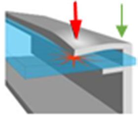
MAXEON SOLAR TECHNOLOGIES, LTD.
537620 Rev.G
SunPower Maxeon 6 AC Residenal Solar Panel
(SPR-MAX6-XXX-BLK-E3-AC, SPR-MAX6-XXX-E3-AC, SPR-MAX6-XXX-BLK-E4-AC, SPR-MAX6-XXX-E4-AC)
0 0
153 271 525 729 729 525 271 153
0
373 mm
Microinverter
Exclusion Zone
356
249 mm
1032 mm
356
B A
0
1100 mm
1872 mm
Measurement Tolerances are +/-3mm for the Length and Width of the module.
A - Ground Holes (4X Ø 4.2mm)
B - Mounng Holes (4X Ø 6.8mm )
TOP CLAMPS
Mounng Zone
Mounng
Configuraon
Mounng Configuraon Diagram
Locaons Test Load
Downward/Upward
Design Load GEN 5.2 FRAME PROFILE
(distance from corner Downward/Upward
Descripon Front View Back View (Pa) (Pa)
in mm) SIDE FRAME PROFILE END FRAME PROFILE
Long Side Mounng, 271 - 525 +5400/-4050 +3600/-2700
Rails Perpendincular
to Mounng Frame 40 mm 40 mm
525 - 729 +2400/-2550 +1600/-1700
0 - 153 +2400/-2400 +1600/-1600
153 - 271 +2400/-2400 +1600/-1600 32 mm 24 mm
Long Side Mounng,
Point Supported 271 - 525 +5400/-3600 +3600/-2400
525- 729 +2400/-2400 +1600/-1600
0 - 153 +2400/-2400 +1600/-1600
Long Side Mounng, 153 - 271 +1600/-1600
+2400/-2400
Rails Parallel to
Mounng Frame 271 - 525 +5400/-3600 +3600/-2400
525- 729 +2400/-2400 +1600/-1600
Short Side Mounng, BOLTS
Rails Perpendicular 0 - 356 Mounng Zone
+3600/-2400 +2400/-1600 Mounng Mounng Configuraon Diagram
to Mounng Frame Locaons Test Load Design Load
(End Mount) Configuraon
(distance from corner Downward/Upward Downward/Upward
Descripon Front View Back View (Pa) (Pa)
in mm)
Long Side Mounng,
Short Side Mounng,
+2400/-2400 Rails Perpendincular 1100mm Holes +6000/-4000
Point Supported 0 - 356 +1600/-1600 +9000/-6000
to Mounng Frame
(End Mount)
Short Side Mounng,
Long Side Mounng,
Rails Parallel to 1100mm Holes +5400/-5400 +3600/-3600
0 - 356 +2400/-2400 +1600/-1600 Point Supported
Mounng Frame
(End Mount)
1 Design Load considers 1.5 Factor of Safety, Test load = Design load x 1.5. Product Warranty covers only design 4 In the cases where hybrid mounng is necessary (combinaon of long and short side mounng), the lowest
load values. The design loads listed in this table supersede all other loads that may be defined by other design load values should be considered as allowable design load.
pares, unless there is a formal authorizaon by Maxeon. 5 Boom flange mounng
2 Test loads are for informaon purposes only, design loads should be considered for the project design. 6 Range indicates posioning of the clamp and not the rails
3 Rails must not be under the Microinverter.
©2023 Maxeon Solar Technologies, Ltd. All rights reserved. Specifications included in this document are subject to change without notice. 10MAXEON SOLAR TECHNOLOGIES, LTD.
537620 Rev.G
SunPower Maxeon 6 AC Residenal Solar Panel
(SPR-MAX6-XXX-BLK-E4-AC, SPR-MAX6-XXX-E4-AC)
0 0
153 271 525 729 729 525 271 153
0
137 ± 15mm
373 mm
43 ± 15mm
356
269 mm
1032 mm
Microinverter
Exclusion Zone
356
B A
137 ± 15mm
0
1100 mm
1872 mm
Measurement Tolerances are +/-3mm for the Length and Width of the module.
A - Ground Holes (4X Ø 4.2mm)
B - Mounng Holes (4X Ø 6.8mm )
TOP CLAMPS
Mounng Zone
Mounng
Configuraon
Mounng Configuraon Diagram
Locaons Test Load
Downward/Upward
Design Load GEN 5.2 FRAME PROFILE
(distance from corner Downward/Upward
Descripon Front View Back View (Pa) (Pa)
in mm) SIDE FRAME PROFILE END FRAME PROFILE
Long Side Mounng, 271 - 525 +5400/-4050 +3600/-2700
Rails Perpendincular
to Mounng Frame 40 mm 40 mm
525 - 729 +2400/-2550 +1600/-1700
0 - 153 +2400/-2400 +1600/-1600
153 - 271 +2400/-2400 +1600/-1600 32 mm 24 mm
Long Side Mounng,
Point Supported 271 - 525 +5400/-3600 +3600/-2400
525- 729 +2400/-2400 +1600/-1600
0 - 153 +2400/-2400 +1600/-1600
Long Side Mounng, 153 - 271 +1600/-1600
+2400/-2400
Rails Parallel to
Mounng Frame 271 - 525 +5400/-3600 +3600/-2400
525- 729 +2400/-2400 +1600/-1600
Short Side Mounng, BOLTS
Rails Perpendicular 0 - 356 Mounng Zone
+3600/-2400 +2400/-1600 Mounng Mounng Configuraon Diagram
to Mounng Frame Locaons Test Load Design Load
(End Mount) Configuraon
(distance from corner Downward/Upward Downward/Upward
Descripon Front View Back View (Pa) (Pa)
in mm)
Long Side Mounng,
Short Side Mounng,
+2400/-2400 Rails Perpendincular 1100mm Holes +6000/-4000
Point Supported 0 - 356 +1600/-1600 +9000/-6000
to Mounng Frame
(End Mount)
Short Side Mounng,
Long Side Mounng,
Rails Parallel to 1100mm Holes +5400/-5400 +3600/-3600
0 - 356 +2400/-2400 +1600/-1600 Point Supported
Mounng Frame
(End Mount)
1 Design Load considers 1.5 Factor of Safety, Test load = Design load x 1.5. Product Warranty covers only design 4 In the cases where hybrid mounng is necessary (combinaon of long and short side mounng), the lowest
load values. The design loads listed in this table supersede all other loads that may be defined by other design load values should be considered as allowable design load.
pares, unless there is a formal authorizaon by Maxeon. 5 Boom flange mounng
2 Test loads are for informaon purposes only, design loads should be considered for the project design. 6 Range indicates posioning of the clamp and not the rails
3 Rails must not be under the Microinverter.
©2023 Maxeon Solar Technologies, Ltd. All rights reserved. Specifications included in this document are subject to change without notice. 11MAXEON SOLAR TECHNOLOGIES, LTD.
537620 Rev.G
SunPower Performance 3 Residenal AC Solar Panel
(SPR-P3-XXX-BLK-E3-AC, SPR-P3-XXX-BLK-E4-AC)
0 0
50 180 472 690 690 472 180 50
0
355 mm
350
1086 mm
1038 mm
565 mm
MICROINVERTER
EXCLUSION ZONES
350
B A
0
1100 mm
1300 mm
1500 mm
1690 mm
Measurement Tolerances are +/-3mm for the Length and Width of the module.
A - Ground Holes (4X Ø 4.2mm)
B - Mounng Holes (8X Ø 6.8mm)
TOP CLAMPS
Mounng Mounng Configuraon Diagram Mounng Zone
Locaons Test Load Design Load GEN 4.3 FRAME PROFILE
Configuraon Downward/Upward Downward/Upward
(distance from corner
Descripon Front View Back View
in mm)
(Pa) (Pa)
SIDE FRAME PROFILE END FRAME PROFILE
50 - 180 +2400/-2400 +1600/-1600
Long Side Mounng,
Rails Perpedincular to
35 mm
35 mm
180 - 472 +5400/-2400 +3600/-1600
Mounng Frame
472 - 690 +2400/-2400 +1600/-1600
Corner Mounng, 0 - 50 +2400/-1600 +1600/-1067 32 mm 24 mm
Long Side
Long Side Mounng, 50 - 372 +3600/-1800 +2400/-1200
Rails Parallel to
Mounng Frame 372 - 472 +3600/-2400 +2400/-1600
Short Side Mounng, 0 - 240 +1400/-1400 +933/-933
Rails Parallel to
Mounng Frame
(End Mount) 240 - 340 +2400/-2000 +1600/-1333
Short Side Mounng, 80 - 180 +6000/-2400 +4000/-1600
Rails Perpedincular to
Mounng Frame
(End Mount) 240 - 340 +6000/-2400 +4000/-1600
Design Load considers 1.5 Factor of Safety, Test load = Design load x 1.5. Product Warranty covers only design 4 In the cases where hybrid mounng is necessary (combinaon of long and short side mounng), the lowest
load values. The design loads listed in this table supersede all other loads that may be defined by other design load values should be considered as allowable design load.
pares, unless there is a formal authorizaon by Maxeon. 5 Boom flange mounng
2 Test loads are for informaon purposes only, design loads should be considered for the project design. 6 Range indicates posioning of the clamp and not the rails
3 Rails must not be under the Microinverter.
©2023 Maxeon Solar Technologies, Ltd. All rights reserved. Specifications included in this document are subject to change without notice. 12MAXEON SOLAR TECHNOLOGIES, LTD.
537620 Rev.G
SunPower Performance 6 Residenal AC Solar Panel
(SPR-P6-XXX-BLK-E8-AC, SPR-P6-XXX-BLK-E9-AC)
0 0
50 402 502 754 754 502 402 50
0
EXCLUSION ZONES
MICROINVERTER
321
638.23 mm
1086 mm
1038 mm
302,77 mm
321
90 mm
AC Clips
235 mm
B A
0
1100 mm
1808 mm
Measurement Tolerances are +/-3mm for the Length and Width of the module.
A - Ground Holes (4X Ø 4.2mm)
B - Mounng Holes (4X 9mm (W) x 14mm (L), R4.5mm)
TOP CLAMPS
Mounng Mounng Zone
Configuraon
Mounng Configuraon Diagram Locaons Test Load Design Load GEN 4.4 FRAME PROFILE
(distance from corner Downward/Upward Downward/Upward
Descripon Front View Back View in mm) (Pa) (Pa)
SIDE FRAME PROFILE END FRAME PROFILE
Long Side Mounng,
Rails Perpedincular 303 - 617 +2700/-2000 +1800/-1333
to Mounng Frame 30 mm 30 mm
303- 402 +2000/-2000 +1333/-1333 33 mm
Long Side Mounng, 24 mm
Rails Perpedincular 402 - 502 +5400/-2400 +3600/-1600
to Mounng Frame
502 - 754 +2000/-1800 +1333/-1200
50 - 402 +2000/-2000 +1333/-1333
Long Side Mounng, 402 - 502 +2000/-2400 +1333/-1600
Point Supported
502 - 754 +1400/-1800 +933/-1200
50 - 402 +2800/-1800 +1867/-1200
Long Side Mounng,
Rails Parallel to 402 - 502 +2800/-1800 +1867/-1200
Mounng Frame
502 - 754 +2800/-1800 +1867/-1200
0 - 221 +1400/-1400 +933/-933
Short Side Mounng,
Point Supported
(End Mount)
221 - 321 +1800/-1200 +1200/-800
0 - 221 +1400/-1400 +933/-933
Short Side Mounng,
Rails Parallel to
Mounng Frame
(End Mount) 221 - 321 +1600/-1600 +1067/-1067
Design Load considers 1.5 Factor of Safety, Test load = Design load x 1.5. Product Warranty covers only design 3 In the cases where hybrid mounng is necessary (combinaon of long and short side mounng), the lowest
load values. The design loads listed in this table supersede all other loads that may be defined by other design load values should be considered as allowable design load.
pares, unless there is a formal authorizaon by Maxeon. 4 Boom flange mounng
2 Test loads are for informaon purposes only, design loads should be considered for the project design. 5 Range indicates posioning of the clamp and not the rails
©2023 Maxeon Solar Technologies, Ltd. All rights reserved. Specifications included in this document are subject to change without notice. 13VERSION : G
Instructions de sécurité et d’installation pour les modules SunPower AC
Le contenu du présent document est susceptible d’être modifié sans préavis.
En cas d’incohérence ou de conflit entre la version anglaise et toute autre version de ce manuel (ou document),
la version anglaise prévaudra à tous égards.
Maxeon Solar Technologies, Ltd.
sunpower.maxeon.com/fr/ | sunpower.maxeon.com/be/fr
537620 Rev.GTable des matières
1.0 Introduction................................................................................................................................................................ 3
1.1 Définitions............................................................................................................................................................................. 3
1.2 Exclusion de responsabilité .................................................................................................................................................. 3
1.3 Conformité aux normes de la Commission Électrotechnique Internationale (CEI)) ............................................................. 3
1.4 Garantie limitée ..................................................................................................................................................................... 3
2.0 Consignes de sécurité ................................................................................................................................................................ 3
3.0 Caractéristiques électriques....................................................................................................................................................... 3
3.1 Résistance au feu ................................................................................................................................................................ 4
4.0 Branchements électriques ......................................................................................................................................................... 4
4.1 Mise à la terre ..................................................................................................................................................................... 4
4.2 Raccordement aux circuits AC ............................................................................................................................................. 4
4.3 Chemin de câble .................................................................................................................................................................. 4
4.4 Raccordement des micro-onduleurs.................................................................................................................................... 5
5.0 Montage des modules ............................................................................................................................................................... 5
5.1 Considérations relatives au site ............................................................................................................................................ 5
5.2 Considérations d’installation ................................................................................................................................................ 6
5.3 Manipulation des modules lors de l’installation................................................................................................................... 7
6.0 Maintenance .............................................................................................................................................................................. 7
7.0 Dépannage ................................................................................................................................................................................. 7
8.0 Annexe (informations techniques complémentaires) ............................................................................................................... 7
Caractéristiques électriques et détails du cadre des modules .......................................................................................................... 8You can also read