ROMY: a multicomponent ring laser for geodesy and geophysics
←
→
Page content transcription
If your browser does not render page correctly, please read the page content below
Geophys. J. Int. (2021) 225, 684–698                                                                                             doi: 10.1093/gji/ggaa614
Advance Access publication 2021 January 05
GJI Seismology

ROMY: a multicomponent ring laser for geodesy and geophysics

Heiner Igel,1 Karl Ulrich Schreiber,2 André Gebauer,1,2 Felix Bernauer,1 Sven Egdorf,1
Andrea Simonelli,1,* Chin-Jen Lin ,1,† Joachim Wassermann,1 Stefanie Donner,1,§
Céline Hadziioannou ,1,¶ Shihao Yuan ,1 Andreas Brotzer,1 Jan Kodet,2
Toshiro Tanimoto ,3 Urs Hugentobler2 and Jon-Paul R. Wells4
1 Ludwig-Maximilians-University     Munich, Department Earth and Environmental Sciences, Germany. E-mail: igel@geophysik.uni-muenchen.de
2 Fundamentalstation   Wettzell, Technical University Munich, Germany
3 University of California, Santa Barbara, Department of Earth Sciences , California, USA
4 School of Physical and Chemical Sciences, University of Canterbury, and Dodd-Walls Centre for Photonic and Quantum Technologies, Christchurch, New

                                                                                                                                                              Downloaded from https://academic.oup.com/gji/article/225/1/684/6064309 by guest on 10 May 2021
Zealand

Accepted 2020 December 24. Received 2020 December 22; in original form 2020 October 5

                                        SUMMARY
                                        Single-component ring lasers have provided high-resolution observations of Earth’s rota-
                                        tion rate as well as local earthquake- or otherwise-induced rotational ground motions. Here,
                                        we present the design, construction and operational aspects of ROMY, a four-component,
                                        tetrahedral-shaped ring laser installed at the Geophysical Observatory Fürstenfeldbruck near
                                        Munich, Germany. Four equilateral, triangular-shaped ring lasers with 12 m side length provide
                                        rotational motions that can be combined to construct the complete vector of Earth’s rotation
                                        from a point measurement with very high resolution. Combined with a classic broad-band
                                        seismometer, we obtain the most accurate 6 degree-of-freedom ground motion measurement
                                        system to date, enabling local and teleseismic observations as well as the analysis of ocean-
                                        generated Love and Rayleigh waves. The specific design and construction details are discussed
                                        as are the resulting consequences for permanent observations. We present seismic observations
                                        of local, regional and global earthquakes as well as seasonal variations of ocean-generated
                                        rotation noise. The current resolution of polar motion is discussed and strategies how to further
                                        improve long-term stability of the multicomponent ring laser system are presented.
                                        Key words: Earth rotation variations; Geodetic instrumentation; Earthquake ground motions;
                                        Rotational seismology; Seismic instruments; Seismic noise.

                                                                                laser beams (e.g. Schreiber et al. 2006b) that is directly proportional
1 I N T RO D U C T I O N
                                                                                to the rotation rate perpendicular to the plane of the laser beams.
Sensing rotational motions in general has a wide range of appli-                   An extremely sensitive ring laser system (G-ring) was installed in
cations, reaching from the control of robotic movements, naviga-                2002 at the Geodetic Observatory Wettzell (Schreiber et al. 2009b)
tion tasks in flight and space operations, to measuring Earth’s and             measuring the local component of rotation around the vertical axis.
planetary rotation, rotational ground motions due to earthquakes,               The G-ring was specifically designed for geodesy, built on a mono-
and vibrations of buildings. Optical Sagnac interferometers such                lithic Zerodur structure, buried underground, thus providing suffi-
as passive fibre-optic gyros or active ring laser gyros outperform              cient long-term stability to be able to resolve tidal effects and polar
mechanical devices by orders of magnitude and are the technical                 motion (e.g. Schreiber et al. 2003, 2011). As with many observation
choice for high-resolution, broad-band observations of rotational               systems one person’s noise is another person’s signal. The G-ring
motions in geodesy and geophysics (Schreiber et al. 2014). Output               observations of Earth’s rotation are superimposed by local rota-
of the ring laser is the beat frequency of two counterpropagating               tional ground motions from a variety of sources. The unprecedented
                                                                                high-resolution (single-component) ground rotational observations
                                                                                of the G-ring of local, regional and teleseismic earthquakes (Igel
∗ Now at: INFN, Pisa, Italy.                                                    et al. 2005, 2007; Cochard et al. 2006) triggered research into the
† Now at: Academia Sinica, Taipei, Taiwan.                                      potential of using additional rotation components for seismological
§ Now at: Bundesanstalt für Geowissenschaften, Hannover, Germany.              research questions. The observation of rotations was already pro-
¶ Now at: University of Hamburg, Germany                                        moted by theoretical seismologists like Aki & Richards (2002) for

                       C The Author(s) 2021. Published by Oxford University Press on behalf of The Royal Astronomical Society. This is an Open Access

                       article distributed under the terms of the Creative Commons Attribution License (http://creativecommons.org/licenses/by/4.0/), which
684                    permits unrestricted reuse, distribution, and reproduction in any medium, provided the original work is properly cited.
ROMY: a ring laser for geodesy and geophysics                 685

a number of reasons, clearly pointing out that there is a lack of sen-       The substantial interest in high-resolution rotation sensing both in
sors recording this type of ground motion. Many developments of           geophysics and geodesy motivated the proposal to build a large mul-
this new field (rotational seismology) in terms of instrumentation,       ticomponent ring laser system that serves both research fields. Here,
theory and applications have been documented in recent review ar-         we describe the four-component ring laser ROMY (an acronym for
ticles (Igel et al. 2015; Li & van der Baan 2017; Schmelzbach et al.      ROtational Motions in seismologY) installed in the Geophysical Ob-
2018) and two special issues (Lee et al. 2009; Igel et al. 2012).         servatory Fürstenfeldbruck, Germany, in its final configuration and
From an instrumentation point of view these developments can be           present first observations.
subdivided into two categories: (1) the high-resolution observatory-         The paper is structured as follows. We (1) first discuss the vari-
style recording systems like ring lasers as discussed in this paper       ous aspects that went into the final technical design of the ring laser
and (2) portable rotation sensors that only recently are considered fit   instrument. This will be followed by (2) a brief description of the
for the specific requirements of seismic ground observations (e.g.        construction phase, (3) the operational principles and (4) data anal-
Bernauer et al. 2012, 2018; Wassermann et al. 2020; Yuan et al.           ysis and a first review of the type of observations we obtain. This
2020b).                                                                   involves the observation of the complete vector of Earth’s rotation
   On the high-resolution side, ring lasers were identified to poten-     as a function of time, high-resolution rotational ground motion due
tially improve and contribute to the observation of Earth’s free os-      to earthquakes and ocean-generated seismic noise.
cillations (Widmer-Schnidrig & Zuern 2009), where tilt induced by

                                                                                                                                                    Downloaded from https://academic.oup.com/gji/article/225/1/684/6064309 by guest on 10 May 2021
local atmospheric pressure fluctuations can substantially deteriorate
classic seismometer observations. Indeed, toroidal-free oscillations
                                                                          2 R O M Y: D E S I G N C O N S I D E R AT I O N S
could be observed on the G-ring following large earthquakes (e.g.,
Igel et al. 2011; Nader et al. 2012). Also, the waveform match            The main goal of the ROMY project was to build on the success-
between rotational and translational ground motions of SH-type            ful G-ring (e.g. Schreiber et al. 2006a), and GEOSENSOR (e.g.
motions (assuming plane waves) can be exploited to estimate prop-         Schreiber et al. 2009a) concepts for both geodesy and seismology
agation velocities (e.g. Igel et al. 2005, 2007; Cochard et al. 2006).    and to develop a multicomponent ring laser system with higher sen-
This has considerable potential as a one-station method to deter-         sitivity for each component. There are a number of design aspects
mine local velocity structure (e.g. Edme & Yuan 2016; Wasser-             that have a strong impact on the final performance of the instrument.
mann et al. 2016; Keil et al. 2020). Ring laser observations also         The detection sensitivity for a rotational signal strongly depends on
contribute to the discussions on the origin of the ocean generated        the size of the ring cavity, on the actual linewidth of the laser ra-
seismic noise (e.g. Hadziioannou et al. 2012; Tanimoto et al. 2015,       diation in the cavity, as well as on the overall geometrical sensor
2016; Gualtieri et al. 2020). Due to the polarization-filter character-   stability (Pritsch et al. 2007). Therefore, we had to maximize the
istics of rotation observations pure Love waves can be observed on        ratio of the enclosed area (A) over the perimeter (P) of the gyro,
vertical component rotation systems like the G-ring allowing pre-         whilst maintaining the highest possible mechanical stability at the
cise characterization of time-dependent Love-to-Rayleigh energy           same time. Although not related to the aspect of sensitivity, we also
ratios in the microseismic band (e.g. Widmer-Schnidrig & Zuern            required a stable spatial orientation of at least three ring laser in-
2009; Tanimoto et al. 2015, 2016).                                        terferometers, each in a linear independent plane with respect to
   More relevant for field-type seismic experiments are the recent        each other. Therefore, we have chosen a tetrahedral design, which
developments providing seismology with portable broadband rota-           offered the additional opportunity to add a fourth redundant inter-
tion sensor technology (e.g. Bernauer et al. 2012, 2018; Brokesova        ferometer in order to achieve a better control over the consistency of
et al. 2012; Jaroszewicz et al. 2012). With appropriate sensitiv-         the ROMY performance. By placing the apex of the tetrahedron at
ity there is a broad spectrum of applications ranging from tilt-          the bottom, we have considerably reduced the required excavation
corrections to improve the quality of classic seismometer records         at the construction site. The stability of ROMY is also inherently
(Lindner et al. 2017; Bernauer et al. 2020), to site-effect characteri-   high, as the scale factor defining corner points of all four rings are
zation (e.g. Keil et al. 2020), seismic source inversion (e.g. Donner     closely spaced together on a massive concrete foundation. With all
et al. 2016), separation of wavefields (e.g. Sollberger et al. 2018),     these aspects working in our favour, we nevertheless had to make a
volcano seismology (e.g. Wassermann et al. 2020), seismic explo-          compromise for the sensor sensitivity.
ration (e.g. Li & van der Baan 2017) or structural engineering (e.g.         Very large ring lasers have predominantly been designed as
Trifunac 2009; Schreiber et al. 2009c). The current portable rota-        squares or rectangles (Dunn et al. 2002; Hurst et al. 2004) in order
tion sensing technology is not sensitive enough to measure below          to optimize their sensitivity. Since we have to maximize the ratio of
the physical noise level of our planet (e.g. ocean-generated noise).      A/P and at the same time to minimize the line broadening losses in
However, observatory-type ring laser technology may provide the           the cavity, the best performance of a gyro is obtained by maximizing
required sensitivity.                                                     the worth function γ = P·n A
                                                                                                       , where n is the number of loss incurring
   Finally, ring lasers allow the most accurate ground-based mea-         mirrors in the cavity. For our well-established G-ring this worth
surement of Earth’s rotation. A single-component horizontally             function yields γ = 0.25 and it was a design criterion to make each
aligned ring laser, such as the G-ring, provides only a scalar quantity   ring of ROMY at least twice as good, which led to the design length
of the rotational component around the local vertical axis projected      of each side of ROMY of 12 m, providing a value of γ = 0.58,
onto the axis of Earth’s rotation. This motivates the development of      assuming that the losses induced by the mirrors are comparable in
an (at least) three-component ring laser sensor that allows for the       both types of gyros, which is a reasonable expectation.
recovery of the complete vector of Earth’s rotation. In addition to          The final ring laser geometry is illustrated in Fig. 1(a). Three
directly measuring changes in Earth’s rotation rate and polar mo-         inclined triangular ring lasers are oriented such as to maximize the
tion (e.g. Schreiber et al. 2004), it has been argued that ring laser     normal vector projection with respect to Earth’s rotation (see section
measurements of the complete rotation vector ideally complement           on ROMY construction for details). The tetrahedron is inverted with
classic VLBI (Very Long Baseline Interferometry) observations             the tip pointing vertically down. Each triangular ring laser has its
(e.g., Mendes Cerveira et al. 2009; Gebauer et al. 2020).                 own independent cavity enclosed by a vacuum recipient, a laser gain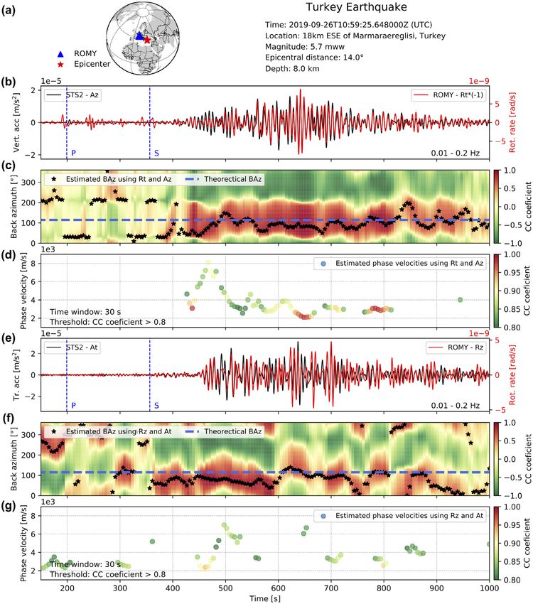
686       H. Igel et al.

                                                                                 construction the circumference of the top ring laser component is
                                                                                 slightly smaller than the inclined ones (see Fig. 1a).
                                                                                    A tetrahedral shape with the tip pointing downwards leaves free-
                                                                                 dom for the orientation of the three inclined faces. Ring lasers
                                                                                 are active Sagnac interferometers. Earth rotation generates a beat
                                                                                 note that biases all geophysical signals away from zero well outside
                                                                                 the lock-in regime. Therefore, the normal vector of each triangular
                                                                                 plane should be as non-orthogonal to the Earth rotation vector as
                                                                                 possible in order to make this bias value large. In ROMY, this is
                                                                                 realized by having one of the faces aligned with the N-direction,
                                                                                 while the others point in the easterly and westerly direction respec-
                                                                                 tively. This achieves nearly equal projections on the Earth rotation
                                                                                 axis (see Fig. 1a).

                                                                                 3 R O M Y: C O N S T RU C T I O N

                                                                                                                                                             Downloaded from https://academic.oup.com/gji/article/225/1/684/6064309 by guest on 10 May 2021
                                                                                 ROMY is a highly sensitive rotation sensor, which is operated in a
                                                                                 strap-down configuration. This means that the ring laser structure
                                                                                 has to be rigidly attached to the Earth’s crust in order to guarantee
                                                                                 that the recorded rotations in fact represent the ground motion.
Figure 1. The ROMY geometry and hardware. (a) Tetrahedral geometry of            A design goal is the reliable detection of rotation rates of less
the ROMY ring laser. The grey shaded cylinders illustrate the shafts that give   than 1 prad s−1 in all three spatial directions. With an arm length
access to ring laser corners and laser activation units. (b) Drawing showing     of 12 m for each of the sides of the tetrahedron, this sets high
the vacuum tubes that contain the laser light (dark yellow) as well as the       requirements for the mechanical monument structure. At the same
corner box with the reflective mirrors (green). The light intensity with the
                                                                                 time it requires a careful procedure for the construction process
Sagnac signal can be measured through the rear window. (c) The bottom of
the ROMY structure with the corners of the three inclined ring lasers rigidly
                                                                                 itself, in order to ensure as little ground settling motions as possible.
connected on a steel base plate attached to a concrete slab. (d) Corner box of   Furthermore, excavations had to be reduced to a bare minimum in
one of the inclined ring lasers. Drawings courtesy of FMB GmbH, Berlin.          order to maintain the overall terrain stability. In the first phase, the
                                                                                 seamless integration of the concrete monument into the local terrain
                                                                                 took place (Fig. 2a). This provided a rigid mounting platform for
section and a data acquisition system. Each corner as well as the tip            the beam lines of the laser interferometers. Since the scale factor of
of the tetrahedron (at the bottom of the structure) can be accessed              the gyros depend on the size of the enclosed area, the size had to
through a circular vault for installation and maintenance. These                 be as stable and as large as possible. Therefore, it was important to
corners are illustrated through technical drawings in Figs 1(b)–                 make the concrete support massive.
(d). The laser radiation is accessible by the light leakage through
the mirrors at each corner exiting through a viewport at the back
of the vacuum enclosure. To establish a closed optical path an
                                                                                 3.1 Concrete structure
external alignment laser is injected into the cavity. All corner boxes
can be rotated and tilted gently to obtain lasing. Note the bottom               The design of the ring laser monument required further considera-
installation of the three corners, fixed to a rigid base plate attached          tions. In order to reduce detrimental strain effects induced by wind
to the concrete basement connected to the bedrock. This gives a                  friction (Gebauer et al. 2012), the top horizontal part of the con-
rigid geometrical reference for the ring laser orientation.                      crete structure was required to be some 3 m underground. This also
   The (temporal) stability and noise level of each ring laser compo-            provides a better thermal isolation for an improved sensor stability.
nent depends strongly on keeping the triangular geometry as rigid as                Eventually the following procedure was adopted: (1) excavate
possible. The G-ring (Schreiber et al. 2009b) is very stable because             the required volume entirely, (2) secure the embankment with a
the entire body of the interferometer is built as a monolith from                shotcrete reinforcement, anchored to the surrounding terrain by
Zerodur, thermally almost a zero-expansion material. To apply the                long bolts, (3) construction of a massive concrete structure from
same design to ROMY would be prohibitively expensive, therefore                  bottom to top rigidly supporting the inclined and horizontal beam
we applied a heterolithic approach, where a solid concrete founda-               lines of the laser cavities and (4) adding a large circular access
tion provides the geometrical reference. One of the corner boxes                 shaft at the centre and smaller vaults at each top corner and halfway
in each ring laser component is adjustable by a piezo actuator in                between them. This provides the necessary service access points for
order to compensate thermal expansion. Utilizing an active control               the alignment of the laser cavities and the gain sections of the laser
of the optical frequency in the cavity will eventually make ROMY                 excitation.
a virtual monolithic structure.                                                     Due to the fact that the mirror supports are on two different
   In principle, three ring lasers would be sufficient to reconstruct the        floor levels, approximately 10 m apart in height and that the entire
Earth’s rotation vector and observe the complete rotational ground               structure has to be stable to within a few wavelengths (≈3 μm),
motion. While three inclined triangular cavities are enough to re-               it was required that the entire soil structure around the ROMY
construct the full Earth rotation vector, the final design included              monument had to be left intact as far as possible. Removing and
an additional interferometer in the horizontal plane, thus providing             subsequently refilling large quantities of soil for a larger building
the vertical component of rotation additionally. This allows us to               structure would destabilize the terrain and gives rise to a subtle
directly compare observations with the well established G-ring at                and continuous creep motion over many years until the soil has
a distance of around 200 km. Note that due to limitations in the                 compacted again. For the installation of a laser interferometer this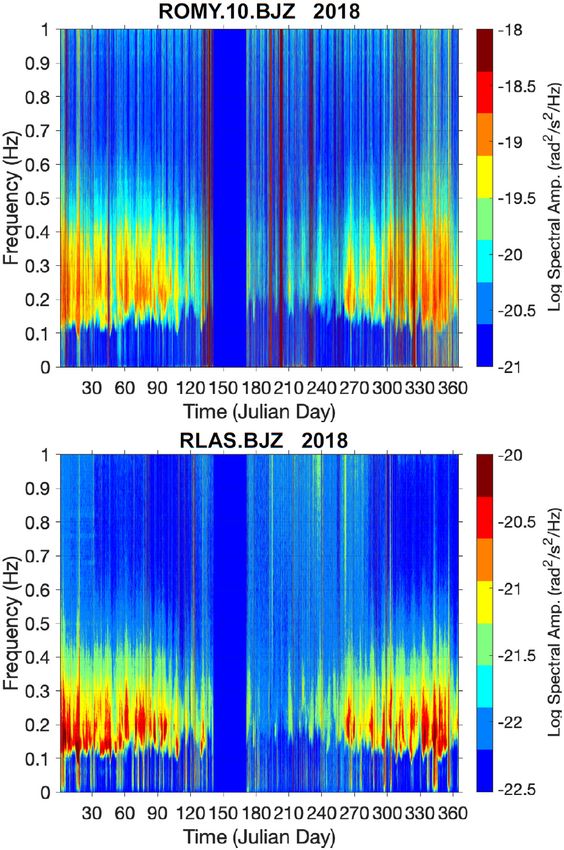
ROMY: a ring laser for geodesy and geophysics                        687

                                                                                                                                                                        Downloaded from https://academic.oup.com/gji/article/225/1/684/6064309 by guest on 10 May 2021
Figure 2. ROMY construction and final installation: (a) Drone view of the excavated volume, the concrete hull and the top-up construction of the tetrahedral
structure (photo: Fa. Wadle). (b) Examples of laser light generation at the centre of the horizontal side tubes. (c) Setup of the rigid bottom plate with the corners
of the three inclined ring lasers. (d) View down the central shaft to the tip of the tetrahedron shown in (c). [(b)–(d) photos: J. Igel].

is clearly not adequate. Since the surrounding terrain was sup-                       the desired transverse TEM0, 0 laser mode. Higher order transversal
ported by a strong retaining wall during the excavation process,                      modes with a larger mode volume, however, are discouraged by
the creep of the terrain could be minimized. When the terrain was                     increased loss. There are no additional Brewster windows or other
refilled after the integration of the monument, care was taken to                     loss increasing components anywhere inside the cavity. In fact,
properly compact the refill material. The construction phase took                     there are only the three curved super mirrors (radius of curvature =
approximately six months. The final installation is illustrated in                    12 m) as interacting intracavity components with a specified total
Fig. 2(a) and also shown in Hand (2017), supplemented by a video                      loss of approximately 12 ppm per mirror (scatter, transmission and
on youtube (https://youtu.be/MXYV6wNdZm8). This video also                            absorption) in the system.
contains a compressed account of the entire construction phase.                          Since the entire beam path is enclosed by an UHV (ultrahigh
                                                                                      vacuum) compatible enclosure (pipe and mirror box housing), the
                                                                                      resonator can be evacuated and then filled with a mixture from
3.2 Ring laser components                                                             (0.2 hPa) neon and (6.3 hPa) helium. Lasing is achieved by radio
ROMY consists of four individual triangular ring cavities, within                     frequency excitation. Fig. 3 depicts the basic sensor concept. Due
which the laser beams propagate. Three of these rings are tilted by                   to the open gain section, the laser gas distributes all around inside
about 57◦ from the horizontal and there is an apex at the bottom of                   the cavity. Overpressuring the laser cavity increases the homoge-
the monument, 14 m deep, where three corners are joined together                      neous spectral linewidth of the cavity modes and thereby avoids
(Fig. 2d). Angled granite support structures carry the mirror holder                  mode competition (excitation of several neighboring transverse las-
boxes (Fig. 2c), while the corner boxes for the horizontal ring are                   ing modes) in the regime ±90 MHz around the lasing frequency.
directly bolted to the concrete monument. The location of the corner                  Therefore, it is possible to operate the interferometer on a single
boxes define the physical size of the structure and the corners are                   mode per sense of propagation, despite a longitudinal mode spacing
joined by stainless steel pipes to form the beam enclosure. Short                     below 9 MHz. Mode jumps for the laser are nonetheless not infre-
bellows near the corner boxes (Fig. 2c) reduce deformations from                      quent. The 36 m length of the laser cavity can contract or expand
strain and make sure that the mechanical rigidity of the corner                       by up to 3 μm, provided by the increased line broadening, before a
construction is not compromised. In the middle of the uppermost                       mode jump occurs.
side of each triangle, there is a 5 mm wide and 20 cm long capillary                     The 36 m length of the laser cavity contracts or expands by
for laser excitation (Fig. 2b). The width of the capillary also acts as               up to 3 μm, provided by the increased line broadening. Another
a spatial mode filter and has been designed to minimize the loss for                  complication is the large internal stainless steel surface area of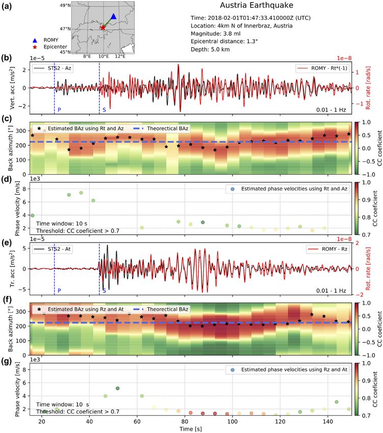
688       H. Igel et al.

                                                                                 Figure 4. Example of the time-domain signal obtained from the horizontal

                                                                                                                                                                Downloaded from https://academic.oup.com/gji/article/225/1/684/6064309 by guest on 10 May 2021
                                                                                 ring. The Sagnac beat note of 553.55 Hz is sampled by 24 bit digitizer at
                                                                                 5 kHz sampling rate.

                                                                                 4.1 Ring laser principle, Sagnac effect
                                                                                 A ring laser gyro constitutes a travelling wave oscillator, where two
                                                                                 beams coexist, one travelling in the clockwise and one travelling
                                                                                 in the counterclockwise direction. The effective length of the oscil-
                                                                                 lator and hence its optical frequency depends on the rotation rate
Figure 3. Schematic of the ring laser setup. Three curved mirrors form the       experienced by the cavity. When the cavity is at rest with respect to
cavity. A capillary on one side acts as a mode selector and provides the laser   an inertial frame of reference the gyro is frequency degenerate and
gain. Lasing is excited by RF excitation of a plasma in the capillary.           the beat note between the two counterpropagating waves disappears.
                                                                                 However, when the gyro is rotated, the effective co-rotating cavity
                                                                                 becomes slightly longer, while the antirotating cavity gets shorter
the vacuum recipient. Although each of the pipes was baked over
                                                                                 by the same amount. The laser oscillation responds by adjusting
several weeks to reduce the outgassing of hydrogen, the residual
                                                                                 the optical frequency of each sense of propagation to fit an integer
diffusion of leaked hydrogen atoms from the pipes into the cavity
                                                                                 number of wavelengths within the cavity, a necessary condition to
is still considerable. Contamination of the laser gas with hydrogen
                                                                                 satisfy laser coherent amplification. This means that the rotation
diminishes the achievable gain from the 3 S2 −→ 2P4 transition at
                                                                                 rate experienced ()˙ around the normal vector n on the laser plane
632.8 nm (red). The application of a CapaciTorr D 200 getter pump
                                                                                 is strictly proportional to the frequency splitting (δf) of the gyro:
in each ring therefore reduces the effect of outgassing considerably
(Schreiber & Wells 2013), thus increasing the system stability. Cur-                     4A
                                                                                 δf =        n· ˙ ,                                                      (1)
rently it is possible to operate each of the four cavities for several                   λP
months on a single gas fill.                                                     where A is the area circumscribed by the beams, λ the wavelength
   In order to obtain a stable beat note, the laser beam power in                and P the perimeter of the gyro contour. The inner product accounts
the cavity has to be stabilized. A small portion of the light leaking            for the projection of the axis of rotation on the normal vector on the
through one of the mirrors is detected and amplified by a photomul-              laser plane. Since ROMY has the shape of an inverted tetrahedron,
tiplier. The resulting voltage is then fed back to drive the power of            each ring has a different projection angle to the Earth’s rotation
the radio frequency transmitter such that the laser radiation in the             axis. Table 1 lists the respective Sagnac beat notes for all four rings
cavity remains constant. At another corner of the interferometer the             with a sample spectrum for the horizontal ring shown in Fig. 5.
two counterpropagating beams are taken out and superimposed via                     Each ring laser is operated at low beam powers of approximately
a beam combiner. The resultant beat note corresponds to the Sagnac               20 nW in order to obtain a stable interferogram. After mixing the
frequency and is strictly proportional to the externally imposed ro-             two counterpropagating laser beams in a beam combiner, the beat
tation rate.                                                                     note is detected by a photomultiplier through the application of a
   Fig. 4 depicts an observed sample interferogram from the hori-                trans-impedance amplifier, then digitized. The resultant waveform
zontal ring laser component. The fidelity of the measurement signal              of all four rings is digitized at a rate of 5 kHz by a 24-bit digitizer unit
(in other words: the signal-to-noise ratio of the spectral line of               (Kinemetrics Obsidian System). The analogue-to-digital processing
Earth’s rotation) is well over 70 dB and the dynamic range may                   flow is described in Section 5.1.
exceed 6 orders of magnitude. The challenge is to properly extract
small variations of this frequency with sufficient stability over long
observation times.                                                               4.2 Unequal mode indices and drifts
                                                                                 Each of the four ring cavities in ROMY has a perimeter over 30 m,
                                                                                 which means that adjacent longitudinal laser modes show a free
4 R O M Y: P R I N C I P L E S O F O P E R AT I O N                              spectral range of only 8.3 MHz for the horizontal ring and 8.9 MHz
                                                                                 for the other rings. Although overpressuring of the resonator with
The principle of ring lasers and the history have been well docu-
                                                                                 helium suppresses the simultaneous excitation of several adjacent
mented in recent review papers (e.g. Schreiber & Wells 2013). We
                                                                                 longitudinal laser modes and thus mode competition, it cannot
focus here on the essential aspects.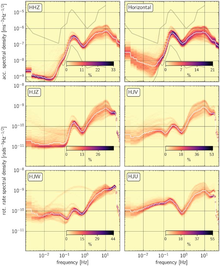
ROMY: a ring laser for geodesy and geophysics                  689

Table 1. The Sagnac beat frequencies (in Hz) obtained for all four compo-      showing the Earth rotation rate is slightly drifting. The interferogram
nents of the ROMY tetrahedron.                                                 jumped to different oscillating laser modes several times during the
Horizontal ring          West ring          North ring          East ring      shown measurement series, which also changed the magnitude of
                                                                               the systematic biases from backscatter coupling (Schreiber & Wells
553.5                      440.4               305.3              439.9
                                                                               2013) and dispersion effects. The system recovered quickly most of
                                                                               the time, but three times throughout this day, the recovery process
                                                                               had to be applied several times before the measurement signal re-
                                                                               turned in the window of detection. Obviously this deteriorates the
                                                                               usability of the observations in particular for low-frequency signals.
                                                                               It is important to note that the potential for slight geometry changes
                                                                               was accepted in the design phase with the knowledge that strategies
                                                                               exist to stabilize these effects in a second construction phase (see
                                                                               Section 6).

                                                                               5 R O M Y: D ATA A N A LY S I S F O R

                                                                                                                                                          Downloaded from https://academic.oup.com/gji/article/225/1/684/6064309 by guest on 10 May 2021
                                                                               GEODESY AND GEOPHYSICS
                                                                               In this section, we present the principles of the frequency-
                                                                               demodulation technique leading to the rotation-rate time-series used
                                                                               in geodesy and geophysics. We document the performance of the
Figure 5. A sample spectrum of the ring laser beat note. The constant bias     ring laser components using the concepts of Allan deviation and
of the Earth rotation rate causes the beat note at 553.5 Hz. Geophysical       power spectral densities. Finally, we show observations of local,
signals from microseismic activity appear as a frequency modulation of this    regional and global seismic wavefields.
carrier at around 0.2 Hz on either side of the main peak.

                                                                               5.1 Data acquisition and processing
                                                                               The Sagnac eq. (1) suggests that the rotation-rate signal at the differ-
                                                                               ent rings are extracted best as a classical frequency demodulation. A
                                                                               schematic flow chart of the data acquisition and processing is pro-
                                                                               vided in Fig. 7. In our case, the carrier frequency or beat note is the
                                                                               (quasi-) constant Earth rotation rate projected on the area normal of
                                                                               the corresponding ring laser component. Additional contributions
                                                                               of (local) rotational ground motions like ocean-generated ground
                                                                               motions, earthquake-induced signals or anthropogenic noise will
                                                                               slightly alter this carrier frequency. The amount of this frequency
                                                                               modulation together with the timing of these changes translates di-
                                                                               rectly into the amplitude–time trace of the rotation rate signal. It
                                                                               is important to note that the ground motion alters the rate of rota-
Figure 6. Example of a typical time-series of the Earth rate bias. Since the
                                                                               tion, experienced by each interferometer in inertial space. Eq. (1)
laser resonator is not length stabilized, the measured Earth rate exhibits a
small drift. The steps in the signal indicate when a mode-jump recovery
                                                                               tells us furthermore that the Sagnac frequency scales with the size
occurred. At three times during this measurement the recovery process          (area divided by circumference) and the orientation with respect to
lasted notably longer. The grey-shaded area indicates the range of expected    the Earth’s rotation vector. As a consequence, the carrier frequency
frequency variations due to changes in Earth’s rotation.                       (constant rotation rate of the Earth) increases with the size of the
                                                                               ring and as the cavity normal vector is increasingly aligned with the
avoid laser oscillation on different neighbouring longitudinal mode            Earth’s rotation vector, thus giving better resolution. For stable ring
indices for each sense of propagation. Although the cavity does not            laser operation, the carrier frequency should be substantially higher
lose the ability to sense rotation, the interferogram is biased by the         than the expected frequency modulations (i.e. perturbations) from
free spectral range into the regime of 8–16 MHz, which is outside              rotation rate variations.
the detection bandwidth of our data logging system. In practice,                  Given the tetrahedral ROMY setup we have to deal with car-
the rotation rate signal disappears from the data logger. ROMY is              rier frequencies between 300–554 Hz (Table 1) with the highest
set up such, that a mode jump like this is detected by a watchdog              frequency signal originating from the horizontal ring (vertical nor-
system on the data logger. In order to recover the interferogram               mal). In order to allow a precise and broad-band rotation rate signal
quickly, the recovery procedure raises the laser power above the               reconstruction, these carrier frequencies have to be sampled with
multimode threshold and then drops the intensity level back to the             a sufficiently high data rate. A sampling frequency of 5 kHz is
preset values, thus providing the chance that the cavity settles down          chosen for all Sagnac channels. The high sampling rate—resulting
such, that both laser modes operate on the same longitudinal mode              in a large amount of raw data to be transmitted in real time—is
index. While this often recovers the gyroscope operations quickly,             essential for the successful demodulation of the rotation rate sig-
the process has to be repeated several times on occasion.                      nal. In order to keep the time base of the sampling as consistent as
   Fig. 6 shows an example from the horizontal ring of ROMY. Due               possible, a 24 channel 24-bit digitizer of the Granite family (Obsid-
to the fact that the cavity length is not stabilized, the interferogram        ian, Kinemetrics) was chosen. The time signal is obtained from a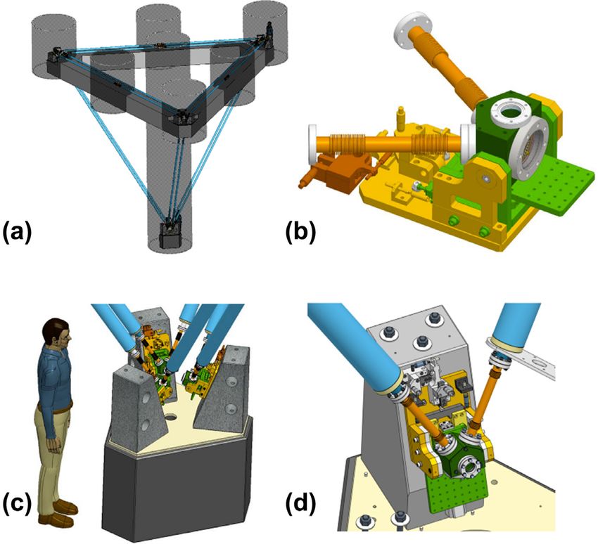
690       H. Igel et al.

Figure 7. Schematic chart of the data acquisition and processing of ROMY.

GPS (Global Positioning System) time source and all channels are
simultaneously sampled.

                                                                                                                                                       Downloaded from https://academic.oup.com/gji/article/225/1/684/6064309 by guest on 10 May 2021
    Next to the four Sagnac beat note channels (Z,U,V,W), there are
provisions to sample the intensity of the eight laser beam channels
(the individual counterpropagating beams) with the same digitizer
and the same sampling rate. The remaining 12 channels are reserved
for a co-located seismometer, tiltmeter, and environmental instru-
ments (temperature, pressure and humidity). The data are transmit-
ted in real time to a seedlink ring server on which a plugin for
near-real time conversion (demodulation) from Sagnac frequency
to rotational motion is implemented. As seismologists are mainly
interested in the frequency band between 0.001 and 10 Hz and the
demodulation should be fast and real time, the demodulation is
done classically by estimating the real and quadrature phase of the
Sagnac signal using a Hilbert transform.
    Before the application of the Hilbert transform and the subse-
quent estimation of the instantaneous frequency (i.e. the rotation
rate signal), the incoming data stream is collected to form batches
of 1600 s of raw, continuous Sagnac-frequency data. There is a slight
overlap with the subsequent window according to the filters applied.
This overlap is in the range of tenths of seconds. The procedure re-
sults in a longest usable period of nominally 800 s and will have to
be modified when investigating free oscillations of the Earth. These
data chunks are subsequently zero-phase bandpass filtered and up-           Figure 8. The Allan deviation σ (τ ) of all four ROMY components. σ (τ )
                                                                            describes the sensor resolution after averaging over a time interval of
sampled to 10 kHz. A Butterworth bandpass filter reduces possible
                                                                            length τ .
side band noise effects. It also performs the required interpolation
during the upsampling process. In order to avoid artefacts of the           algorithm is fast enough to act in real time and serves well for the
filters, the impulse response at 20 times the time–frequency product        most common seismological applications. In the case of very low
of the bandpass filter is removed at the beginning and the end of the       and very high frequencies, however, the raw data has to be treated
1600 s signal segment. This upsampled and filtered signal is then           in different ways and in an off-line mode.
convolved with a truncated time-domain Hilbert filter (Cohen &
Stockwell 2020). The instantaneous frequency is finally estimated
by the approximation:                                                       5.2 Performance

          S(t)dt H [S(t)] − dt S(t)H [S(t)]                                 The performance characteristics of a ring laser gyroscope are com-
f (t) =                                     ,                       (2)     monly described in terms of the Allan (1966) deviation. Originally
               2π (S(t)2 + H [S(t)]2 )
                                                                            designed for the performance characterization of high-precision os-
where f is the instantaneous frequency (i.e. the rotation rate), S(t)       cillators, the Allan deviation σ (τ ) can be calculated as follows:
the Sagnac signal, H[] the Hilbert transform and dt stands for the
                                                                                         ( ȳk+1 (τ ) − ȳk (τ ))2
time derivative.                                                            σ 2 (τ ) =                               ,                          (3)
                                                                                                      2
   In order to keep the resolution as high as possible but still use an
efficient compression algorithm a constant offset value (i.e. constant      with ȳk (τ ) as the kth average value of the time-series y of length τ
part of the rotation rate of the Earth) is removed and the remain-          and  denoting the average over all k along the time-series y. The
ing numbers are scaled to form integers in multiples of 1 μHz.              Allan deviation describes the resolution of the sensor readout after
These integers are further processed by seedlink plugins which ap-          averaging over the time span τ .
ply a Steim2 compression as well as subsequent downsampling                   According to Fig. 8, the ROMY Z- and the V-components show a
to seismologically usable sampling rates (i.e. 100, 20 and 2 Hz,            minimum in Allan deviation of 2.0 and 2.8 prad s−1 , respectively, at
respectively). Despite this very complex procedure the associated           an averaging time of 100 s. The W-component shows the minimum
ROMY: a ring laser for geodesy and geophysics 691
Downloaded from https://academic.oup.com/gji/article/225/1/684/6064309 by guest on 10 May 2021
Figure 9. PPSDs for the co-located vertical and horizontal components of the broad-band station FUR (top row) and all four ROMY components. The white
line indicates the median of the distributions. 1 hr time windows with 50 per cent overlap were used to calculate power spectral densities. For ROMY PPSDs,
we used around 30 continuous recordings each lasting 6 hr during periods of stable operation. In order to demonstrate station performance at low background
noise levels, we exclude strong signals from nearby noise sources like farming machinery, with peak signal amplitudes exceeding 100 nrad s−1 .
of 7 prad s−1 at 70 s averaging time, while the U-component shows machinery, we manually picked around 30 continuous recordings
a minimum of approximately 8 prad s−1 at 400 s averaging time. (for each ring) each lasting 6 hr with peak signal amplitudes not ex-
As a consequence, the best-performing ring (the Z-component) can ceeding 100 nrad s−1 . Consistent with the Allan deviation analysis
resolve a rotation rate as low as 2 prad s−1 after averaging over 100 s. (Fig. 8), the Z-component (channel HJZ in Fig. 9) shows the low-
For the best-performing rings, the sensitivity at 1 Hz (averaging time est noise levels over a period range from 1000 to 10 s. This might
of 1 s) is between 80 and 100 prad s−1 which is still exceptional. At be related to the fact that the corners of this ring laser component
this point in time, the performance at lower frequencies (692 H. Igel et al.
5.3 Earth’s rotation region of Papua New Guinea on 2019 May 14. The epicentral
distance was 125◦ (≈ 14 000 km). The seismometer data were
ROMY has twice the scale factor (the proportional factor in eq. 1)
rotated into a local RTV (radial-transverse-vertical) system, and the
of the G-ring laser. So it is sensitive enough to measure variations
original velocity data were instrument-corrected and converted to
in the rate of Earth rotation, provided that the stability of the entire
ground acceleration. The four-component ROMY ring laser data
installation can be improved to take the knee of the Allan deviation
were combined to a ZNE system and then also rotated into an RTZ
of Fig. 8 down to 1 part in 109 of Earth’s rotation. Expressed dif-
system. All traces were bandpass filtered in the interval [0.01 −
ferently, a laser gyro for Earth rotation monitoring has to resolve
0.1 Hz].
a rotation rate of less than 0.01 prad s−1 . Furthermore, it has to
In Figs 10(b)–(d), the vertical component of the ground acceler-
remain stable for several weeks. ROMY as opposed to any of the
ation Az and the transverse component of the ground rotation rate
other single-component large ring lasers existing today, can resolve
Rt (multiplied by a factor −1 to achieve phase match) are analysed.
the complete Earth rotation vector in a self-contained fashion, be-
The traces of acceleration (black) and rotation rate (red) are super-
cause all three components of rotation in space are captured by the
imposed, the arrival time of the SS phase is marked. Across almost
individual rings. On top of that, there is one extra ring available,
the entire time window the phase match between both traces is (vi-
which offers redundancy to check for consistent operation.
sually) excellent indicating that the wave fronts are close to planar
At appropriate resolution the ground-based observations of the
and that body wave P–SV motions and Rayleigh wave motions are
Earth’s full rotation vector certainly would be a desired comple-
Downloaded from https://academic.oup.com/gji/article/225/1/684/6064309 by guest on 10 May 2021
correlated as expected from simple plane wave theory (e.g. Li et al.
ment to VLBI (e.g., Mendes Cerveira et al. 2009). Gebauer et al.
2002). The amplitude match between rotation rate and vertical ac-
(2020) report a first discussion of the initial ROMY ring laser per-
celeration is achieved by scaling with an apparent horizontal phase
formance with respect to geodetic requirements. Over a length of
velocity of ≈ 3 km s−1 .
47 d, a long-term sensor stability of / = 5 × 10⁻⁵ —where
To further characterize the teleseismic ground motions, we cal-
is Earth’s rotation rate—could be achieved. In an Earth-centred
culate the correlation coefficient between vertical acceleration and
frame of reference, this corresponds to an orientation change of the
rotation rate as a function of assumed backazimuth in a 50 s slid-
rotation axis of around 0.1 arcsec, which translates into ≈3 m of
ing time window. The maximum correlation is denoted by a black
polar motion. While this is the most accurate direct measurement
dot that scatters around the theoretical backazimuth (dashed blue
of the Earth’s complete rotation vector by a ring laser, it clearly
line) and is very stable in the expected propagation direction in the
needs improvement. This can be achieved by the full implementa-
window containing the Rayleigh waves. Apparent phase velocities
tion of the cavity stabilization procedure and is planned for the near
are estimated whenever the waveform match exceeds 0.95 correla-
future.
tion coefficient (Fig. 10d). The high phase velocities around the SS
arrival are due to the steep incidence angles of P–SV body-wave
5.4 Earthquake-induced ground motions phases. The highest correlations (colour coded) are observed in
the time window containing the Rayleigh wave energy with phase
The recording and analysis of broad-band rotational ground motions velocities between 2.5 and 4.0 km s−1 .
is a recent, but emerging field and most previous observational stud- In Figs 10(e)–(g), the corresponding analysis is carried out for
ies were limited to either single-component ring laser systems (e.g. the vertical component of rotational motions Rz and the transverse
Igel et al. 2005, 2007; Cochard et al. 2006), or array-derived rota- acceleration At, as was previously done using data from the G-ring
tional motions (e.g. Huang 2003). An event database exists (Salver- laser (e.g. Igel et al. 2007). In this case, the ring laser is sensitive to
moser et al. 2017) into which seismic events recorded on the G-ring SH-type motions only. Prior to the SS arrival, there is substantially
laser and—as of recently—the ROMY ring laser are written on a less energy in the vertical rotation than in the horizontal component
daily basis. In the past few years, portable broadband sensors that (discussed above), as expected for a predominantly spherically sym-
measure rotational ground motions have been developed (Bernauer metric Earth. The backazimuth estimation is stable almost along the
et al. 2018) and are now being applied in the field (e.g. Yuan et al. entire seismograms. The indication of surface wave dispersion in
2020b; Wassermann et al. 2020). However, it is important to note the window containing the Love waves is more apparent than for the
that they are approximately three orders of magnitude less sensi- Rayleigh wave case. However, it is important to note that the phase
tive than the ring laser systems, therefore less capable of capturing velocity estimate can be affected by the superposition of higher
global earthquake-induced wavefields with a comparable sensitivity surface wave modes (e.g. Kurrle et al. 2010).
as classic broad-band seismometers.
In the following sections, we will show exemplary seismic ob-
servations from the classic seismic distance categories. A detailed 5.4.2 Regional seismic event
analysis will be provided in a follow-up study. The innovation for
seismology with the ROMY ring laser (compared to previous ring An example of a regional seismic event at a distance of around
laser observations) is the possibility to observe directly the hori- 1500 km that occurred in Turkey 2019 September 26 with a mag-
zontal components of rotational motions (i.e. tilt rate) allowing also nitude Mw 5.7 is shown in Fig. 11. The processing and graphical
the analysis of P–SV (and Rayleigh surface wave) motions with representation is identical to the teleseismic event. The data have
unprecedented accuracy. been bandpassed in the interval [0.01–0.2 Hz]. The waveform fit
between appropriately rotated acceleration and rotation rate signals
is less pronounced than in the teleseismic case. Due to the higher
5.4.1 Teleseismic event frequencies involved we expect stronger effects due to non-planar
wave fronts and scattering in general. There is also consequently
In Fig. 10, ground motion observations recorded in
more scattering of the backazimuth that has highest correlation and
Fürstenfeldbruck, Germany, with the seismic broadband (STS2)
there seems to be a systematic shift away from the true backazimuth
station FUR and the ROMY ring laser (at a distance of approx-
in both SH- and P–SV-type setups (except for some time windows
imately 20 m) are shown following the M7.6 earthquake in the
with very high correlations).ROMY: a ring laser for geodesy and geophysics 693
Downloaded from https://academic.oup.com/gji/article/225/1/684/6064309 by guest on 10 May 2021
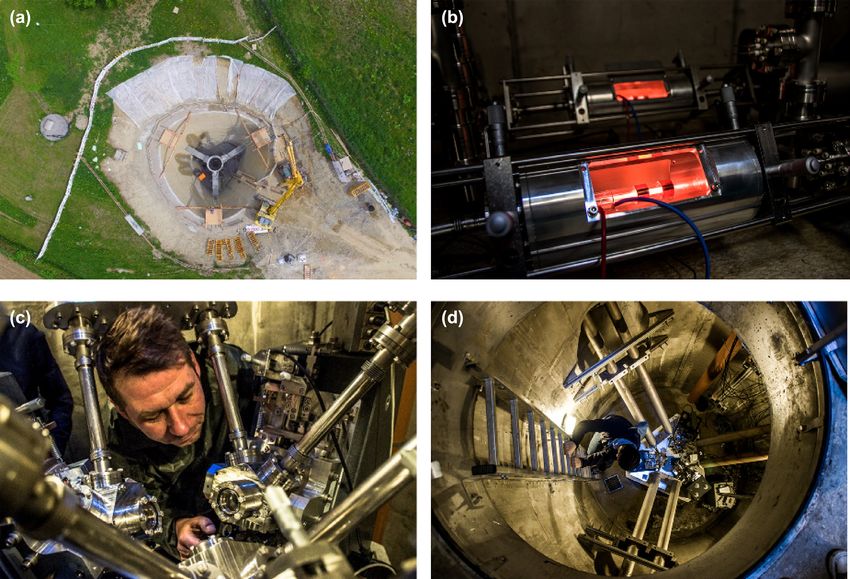
Figure 10. Observed translational and rotational motions for the M7.6 Papua New Guinea earthquake, 2019 May 14. (a) Earthquake information and schematic
view of the great-circle path through the epicentre and ROMY in Fürstenfeldbruck, Germany. (b) Superposition of the bandpass filtered (0.01–0.1 Hz) vertical
acceleration (Az) and transverse rotational rate (Rt). (c) Estimated BAz for each 50 s sliding time window (black stars) using the cross-correlation (CC) method
between Az and Rt. The colour scale denotes the CC coefficient. The dashed blue line denotes the theoretical BAz. (d) Estimated phase velocities with CC
coefficients higher than 0.9 for each sliding window using Az and Rt. (e)–(g) The same as (b)–(d), respectively, but for transverse acceleration (At) and vertical
rotational rate (Rz), which focus on Love-type waves.
While the Rayleigh wave phase velocity estimates in the time In this local event case, the correlation of the SH-type motion
windows with high correlations (e.g. = 610 s) are comparable seems consistently higher compared to the P–SV case. What is
with those for the teleseismic event, the Love wave phase velocity remarkable is the lack of energy in the SH case prior to the S-
estimates (Fig. 11g), are estimated at the lower end of the correlation wave arrival. Whether the low Love-wave phase velocities of around
scale and are questionable. 1.5 km s−1 are compatible with local velocity estimates remains
to be checked. While the correlations for the P–SV case are in
general high (i.e. substantially above values of 0.7), phase velocity
5.4.3 Local seismic event estimates should be treated with care (we usually treat them as
A comparably strong local event occurred at a distance of 144 km reliable whenever coefficients exceed 0.85).
south of the Germany–Austria border with a local magnitude of
ML 3.8 on 2018 February 1, with results shown in Fig. 12. The
5.5 Ocean-generated noise
data were rotated accordingly and bandpass filtered in the interval
[0.01–1 Hz]. Note that the dominant frequency here is substantially One of the outstanding questions on ocean-generated seismic noise
higher than for the event in Turkey. Nevertheless, the waveform (microseisms) is how much Rayleigh and Love waves are con-
correlation in both P–SV and SH cases is high, and the point of tained in the primary microseism (approximately in the range 0.05–
maximum correlation as a function of backazimuth captures fairly 0.07 Hz) and in the secondary microseism (approximately 0.10–
well the actual backazimuth direction. 0.40 Hz). A precise answer to this question is surprisingly difficult694 H. Igel et al.
Downloaded from https://academic.oup.com/gji/article/225/1/684/6064309 by guest on 10 May 2021
Figure 11. The same presentation as Fig. 10 but for the M5.7 Turkey earthquake, 2019 September 26.
because the amount of Love waves is hard to estimate. While verti- plotted from 0 to 1 Hz in the vertical axis. The horizontal axis is
cal component seismograms provide us clean records for Rayleigh the Julian Day. The bottom panel is a similar time–frequency plot
waves, horizontal component seismograms contain both Rayleigh for RLAS. Power spectral densities of rotation are plotted in colour;
and Love waves and their separation is not necessarily easy unless high amplitudes (brown and red) are seen for frequencies between
an array of seismometers is available (Juretzek & Hadziioannou about 0.10 and 0.40 Hz in both data sets. They show seasonal vari-
2016). ations, typically small amplitudes in summer and large amplitudes
The vertical rotation data from a ring laser can provide a unique in winter. These are signals of the ocean-generated secondary mi-
data set to address this question because vertical rotation data pre- croseism.
dominantly consist of Love waves (e.g., Hadziioannou et al. 2012). There is a distinct difference in amplitudes between the two sta-
We have combined the ring laser data with station naming RLAS (G- tions, however. Colour scales on the right-hand side of plots (Fig. 13)
ring) with vertical seismic data at Wettzell to estimate the amount indicate that PSDs from ROMY are about 50–100 times larger than
of Love-wave energy in the secondary microseism that is passing those at RLAS (Wettzell). This must be related to elastic properties
through the station (Widmer-Schnidrig & Zuern 2009; Tanimoto at shallow depths. The site of ROMY is located in an alluvial basin
et al. 2015, 2016). The amount of Love waves was surprisingly (glacial deposits) while Wettzell—the site of a VLBI station—is
large at Wettzell, comparable or slightly larger than the amount of characterized by igneous rocks. This is currently under investiga-
Rayleigh waves throughout a year. tion using 3-D modelling techniques.
New ROMY data, recorded about 200 km to the southwest of ROMY can also provide horizontal rotation data (i.e. tilt). They
Wettzell, provide another opportunity to validate this estimate. Com- are the direct measurements of tilt which would be primarily com-
parison of vertical rotation data from RLAS (Wettzell) and ROMY posed of Rayleigh-wave signals. With three component rotation data
are shown in Fig. 13, plotted for the entire year of 2018. The top at ROMY, in contrast to only vertical rotation data from RLAS, we
panel is a time–frequency plot for the vertical rotation from ROMY, will be able to analyse new aspects of ocean-generated seismicROMY: a ring laser for geodesy and geophysics 695
Downloaded from https://academic.oup.com/gji/article/225/1/684/6064309 by guest on 10 May 2021
Figure 12. The same presentation as Fig. 10 but the M3.8 Austria earthquake, 2018 February 1.
noise from ROMY data and deepen our understanding of this natu- construction was such that the mechanical degrees of freedom of the
ral source. ring laser hardware (in particular the corner boxes and the movable
mirrors) where such that for all four rings the optical paths could be
established allowing the Sagnac effect to be observed. As a conse-
6 D I S C U S S I O N A N D C O N C LU S I O N quence the ground-based reconstruction of the entire vector of Earth
rotation was possible with high accuracy (Gebauer et al. 2020).
ROMY, the name of the EU-funded ERC-Adv project that funded
For seismology, ROMY—combined with the collocated broadband
the construction of the first multicomponent ring laser. It is also an
STS2 sensor (FUR)—constitutes the most accurate 6 degree-of-
indication that originally the ring laser was supposed to primarily
freedom point measurement to date. The ultimate goal of ground
serve as the most sensitive ground rotation recording instrument
motion (including the rotational component) measurements is to
world wide. Through further funding, the original dimensions of
observe below the physical low-noise model of planet Earth. While
the tetrahedral-shaped ring laser system (6 m side length) could
this goal has been achieved with translational sensors decades ago,
be extended to 12 m thereby making it (i) a very interesting sen-
for the rotation component this still constitutes a formidable prob-
sor for geodesy as the theoretical sensitivity exceeds the currently
lem. ROMY—with ocean-generated noise clearly observed—is a
most accurate system, the G-ring; (ii) more prone to instabilities
major step in this direction. Portable sensors (e.g. Bernauer et al.
due to the difficulties in stabilizing the larger geometry and (iii) a
2018) will likely not be able to achieve this goal in the foreseeable
grand challenge as far as the construction was concerned and the
future.
establishment of the optical paths in the triangular cavities.
An important aspect of the specific ROMY design was that tiny
In the light of these challenges, the successful construction of
geometry changes due to thermal or other effects were taken into
the first multicomponent ring laser of this shape and kind can be
account. These usually long-term effects primarily affect geode-
considered a substantial progress in ring laser technology applicable
tic or very long-period seismic observations. An actual monolithic
to geodesy and geophysics. The level of accuracy of the concrete696 H. Igel et al.
we expect the routine observation of local to global seismicity,
ocean-generated noise and Earth’s free oscillations excited by large
earthquakes or infragravity waves in the oceans. Furthermore, the
ROMY system can be used for the investigation of 6 degree-of-
freedom point seismic processing schemes, such as local seismic
velocity analysis (e.g. Wassermann et al. 2016; Keil et al. 2020),
the comparison with array-derived rotation that is installed around
ROMY (e.g., Suryanto et al. 2006; Donner et al. 2017), or the
tracking of seismic sources (e.g. Yuan et al. 2020a).
AC K N OW L E D G E M E N T S
The ROMY ring laser has been funded by an ERC—Advanced
Grant of the European Research Council (ROMY project, grant
number 339991). We are grateful to the leadership of the Ludwig–
Maximilians University providing substantial additional support for
Downloaded from https://academic.oup.com/gji/article/225/1/684/6064309 by guest on 10 May 2021
the construction of ROMY. We thank the Staedtische Bauamt II
for their support. We thank the Bundesamt für Kartographie and
Geodäsie for their support. We thank Stefanie Schwartz for her
help with the ring laser hardware, Jonas Igel for the photo sessions,
Monika Terzjak for her theoretical orientation analysis. We thank
the technical staff of the partner at the University of Canterbury,
New Zealand, for their help. We thank Ruedi Widmer-Schnidrig
and one anonymous reviewer for insightful comments. Data used in
this paper are accessable at https://syncandshare.lrz.de/getlink/fiB
HgQaYanFu1HsZX2A5C6B/GJI-ROMY-2021.
REFERENCES
Aki, K. & Richards, P., 2002. Quantitative Seismology., University Science
Books.
Allan, D.W., 1966. Statistics of atomic frequency standards, Proc. IEEE,
54(2), 221–230.
Bernauer, F., et al., 2018. BlueSeis3A: full characterization of a 3C broad-
Figure 13. Seasonal variations of rotation noise. Top: time–frequency plot band rotational seismometer, Seismol. Res. Lett., 89(2A), 620–629.
of the rotation rate around the vertical axis of the ROMY ring laser in Bernauer, F., Wassermann, J. & Igel, H., 2012. Rotational sensors-a com-
2018 in the interval [0–1 Hz]. Bottom: same for the G-ring laser at Wettzell. parison of different sensor types, J. Seismol., 16(4), 595–602.
In both cases, we clearly see seasonal variations in the secondary marine Bernauer, F., Wassermann, J. & Igel, H., 2020. Dynamic tilt correction
microseismic band with periods in the range of 3–10 s. Note the different using direct rotational motion measurements, Seismol. Res. Lett, 91, 5,
colour scales, indicating the substantial difference in power (see the text for 2872–2880.
details). Brokesova, J., Malek, J. & Kolinsky, P., 2012. Rotaphone, a mechanical
seismic sensor system for field rotation rate measurements and its in situ
structure (as implemented for the G-ring) would have been pro- calibration, J. Seismol., 16(4, SI), 603–621.
hibitively expensive. However, with further modifications to the Cochard, A., et al., 2006. Rotational motions in seismology: theory, observa-
current system (e.g. locking the optical frequency of each ring laser tion, simulation, in Earthquake Source Asymmetry, Structural Media and
to an optical reference and adjusting the laser cavity through mir- Rotation Effects, pp. 391–411eds Teisseyre, R., Majewski, E. & Takeo,
M., Springer Berlin Heidelberg.
ror movements, e.g. Schreiber & Wells 2013) a virtual monolithic
Cohen, J.K. & Stockwell, J.J.W., 2020. Cwp/su: seismic unix release no.
structure shall be established.
44r19: a free package for seismic research and processing, Center for
As indicated in the technical sections above, ROMY is a delicate Wave Phenomena, Colorado School of Mines, https://github.com/JohnW
instrument with a number of problems that affect the quality of StockwellJr/SeisUnix.
the observations. These include effects of deterioration of the gas Donner, S., Bernauer, M. & Igel, H., 2016. Inversion for seismic moment
mixture, a stable optical frequency and equal laser beam power in tensors combining translational and rotational ground motions, Geophys.
the cavities established via a feedback loops, and effects from slight J. Int., 207(1), 562–570.
settling of the monument construction affecting the rigid structure Donner, S., et al., 2017. Comparing Direct observation of strain, rotation, and
and thus the optical path. These problems make it currently difficult displacement with array estimates at Piñon Flat Observatory, California,
to obtain continuous undisturbed multicomponent observations that Seismol. Res. Lett., 88(4), 1107–1116.
Dunn, R.W., Shabalin, D.E., Thirkettle, R.J., MacDonald, G.J., Stedman,
can be combined to generate the desired 3C local ground rotations
G. & Schreiber, K.U., 2002. Design and initial operation of a 367-m2
and Earth’s rotation vector. However, none of these problems are
rectangular ring laser, Applied Optics, 41, 1685–1688.
insurmountable. Edme, P. & Yuan, S., 2016. Local dispersion curve estimation from seismic
With these improvements implemented, we expect stable long- ambient noise using spatial gradients, Interpretation, 4(3), SJ17–SJ27.
term observations, which will allow recovery of variations in the Gebauer, A., et al., 2020. All optical reconstruction of the instantaneous
length of day, a high-resolution time-series of the Earth rotation earth rotation vector from a large scale laser gyroscopic array, Phys. Rev.
vector in order to fuse them with VLBI measurements. In addition, Lett., 125 , 033605, doi:10.1103/PhysRevLett.125.033605.You can also read