SIMULATION OF ELECTRIC ASSISTED BOOSTING SYSTEM IN A MILD HYBRID VEHICLE
←
→
Page content transcription
If your browser does not render page correctly, please read the page content below

GT Conference 2017

                                                      SIMULATION OF ELECTRIC ASSISTED BOOSTING SYSTEM
                                                                                                    IN A MILD HYBRID VEHICLE

Frankfurt, 9th October 2017
Surya Kiran Yadla, D. Lückmann, A. Schlosshauer, A. Müller, K. Kannan, R. Wohlberg, A. Balazs,
T. Uhlmann, M. Thewes
                                                                              © by FEV – all rights reserved. Confidential – no passing on to third parties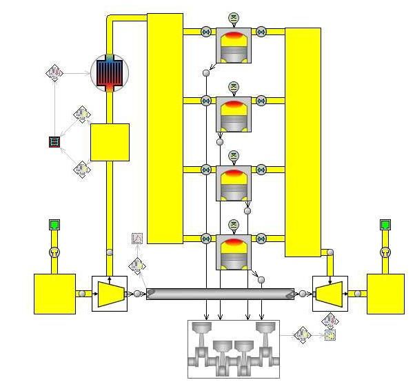
eTC in a 48V Mild Hybrid powertrain
Content
Introduction and motivation
Overview of the simulation and modelling methods
Results of the investigations
Impact of eTC boosting & exhaust energy recovery on engine performance
Transient cycle simulations
Summary and Outlook
Surya Yadla, GT Conference 2017 © by FEV – all rights reserved. Confidential – no passing on to third parties | 2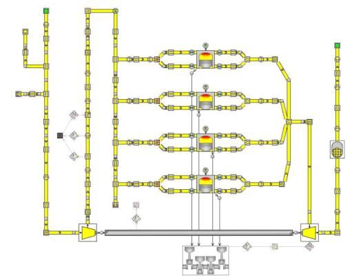
eTC in a 48V Mild Hybrid powertrain
Content
Introduction and motivation
Overview of the simulation and modelling methods
Results of the investigations
Impact of eTC boosting & exhaust energy recovery on engine performance
Transient cycle simulations
Summary and Outlook
Surya Yadla, GT Conference 2017 © by FEV – all rights reserved. Confidential – no passing on to third parties | 3
eTC in a 48V Mild Hybrid powertrain
Major shift towards 48 V mild hybrids & plug-in hybrids in EU; BEV/PHEV
share in 2030 depending on battery development & customer acceptance
FUTURE POWERTRAIN SCENARIOS PASSENGER CAR
2025:
100%
55 % electrified powertrains
6%
18% 20 % PHEV & BEV
80% 39% 90 % with combustion engine
91%
electrified
51% 2030:
drives
60% 85% ICE only 90 % electrified powertrains
St-St & 12 V Energy Mgmt
78% 33% Mild-Hybrid
30 % PHEV & BEV
40% 7%
Full-Hybrid 80 % with combustion engine
3% 13% Plug-In-Hybrid
20% 13% Battery Electric
5% 19% 20%
Fuel Cell
2% 2% 8% w/o ICE
2% 1% Natural Gas and E-Fuels
0% 2% 2% 5% 3%
2016 2020 2025 2030
CO2 fleet
emission:
eTC in a 48V Mild Hybrid powertrain
Content
Introduction and motivation
Overview of the simulation and modelling methods
Results of the investigations
Impact of eTC boosting & exhaust energy recovery on engine performance
Transient cycle simulations
Summary and Outlook
Surya Yadla, GT Conference 2017 © by FEV – all rights reserved. Confidential – no passing on to third parties | 5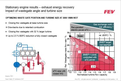
eTC in a 48V Mild Hybrid powertrain
The Belt Starter Generator (BSG) in a P0 layout is the most cost-favorable
entry point for hybridization
P0 MILD-HYBRID WITH BELT STARTER GENERATOR AND ELECTRIFIED TURBOCHARGER
ICE
1.0l, 3Cyl. TC GDI
90 kW @ 5000 1/min
BELT STARTER GENERATOR (BSG)
Front axle Rear axle Peak power 12 kW
Constant power 8 kW
Starter Load point shift, Brake energy
BSG Clutch
recuperation, sailing
ICE E ELECTRIFIED TURBOCHARGER (ETC)
M
Transmission Peak power 6 kW (boosting & recovery)
48 V Constant power 3 kW
Traction
Battery
BATTERY
Li-Ion with 1 kWh
IMPACT OF ETC STRATEGIES ON CO2 EMISSIONS
Optimized Turbocharger matching
Exhaust energy recuperation
Reduced gas exchange losses due to open
wastegate in part load
Surya Yadla, GT Conference 2017 © by FEV – all rights reserved. Confidential – no passing on to third parties | 6eTC in a 48V Mild Hybrid powertrain
The modelling approach can be selected based on the main focus of
investigation
MODELLING APPROACHES
Computational time
Map based approach Map based Gas-Exchange Model Fast Running Model Detailed engine model
30
FMEP / bar
25
20
BMEP / bar
30 15
30
BSFC / (g/kWh)
FMEP / bar 25
10
25 20
BMEP / bar
5 0.5
0 15
20 1000 2000 3000 4000 5000 6000
BMEP / bar
10
30 Engine speed / min-1
BSFC / (g/kWh) 5
15
25 0
1000 2000 3000 4000 5000 6000
10 Engine speed / min-1
20
BMEP / bar
5 0.5
15
Intake Exhaust
0 side From side
1000 10
2000 3000 4000 5000 6000
To Intake
Exhaust
5 Engine speed / min
-1 port
port
0
1000 2000 3000 4000 5000 6000
Engine speed / min-1
Map based engine model Map based engine model Fast Running Engine Model Detailed 1D engine model
Engine transient behavior Gas Exchange path by combining smaller Ideal for stationary load point
estimated with the help of Compressor and Turbine volumes to form larger or transient load step
transient functions along with their adjacent volumes investigations
pipes Transient behavior such as Not suitable for long
Cycle avg. mass flow, temp. turbo lag, intake pressure transient cycle simulations
and pressure values build up and the resulting
engine load can be
No detailed combustion
investigated
modelling
Computational time Computational time Computational time o Computational time
Effort Effort Effort o Effort o
Accuracy o Accuracy o Accuracy Accuracy
Surya Yadla, GT Conference 2017 © by FEV – all rights reserved. Confidential – no passing on to third parties | 7eTC in a 48V Mild Hybrid powertrain
FEV’s Drivetrain Optimization Tool (DOT) helps in analyzing and optimizing
the powertrain - Approach for DoE, Simulation & Optimization
TARGET: OPTIMIZATION OF HYBRID POWERTRAINS FOR CUSTOMER RELEVANT DRIVING CYCLES
Parametric description of combustion engine, Creation of DoE test plan
powertrain and operation strategy
Variation of all parameters within defined constraints
…
DoE Model point
Parameter 2
Variation parameter: Validation point
Repetition point
Engine configuration
Optimized hybrid
Powertrain configuration with all drivetrain for
components customer relevant Parameter 1 Parameter 1
operation
Mathematical modeling and Drive cycle simulation in GT-Drive
numerical optimization CO2 Different powertrain models
Impact of all var. Simulation of customer relevant driving
parameters on CO2 – DoE Model cycles
emissions
Vehicle
Speed
Consideration of
constraints, e. g.
performance Parameter 1 Parameter 2
Time
Source: FEV
Surya Yadla, GT Conference 2017 © by FEV – all rights reserved. Confidential – no passing on to third parties | 8eTC in a 48V Mild Hybrid powertrain
Content
Introduction and motivation
Overview of the simulation and modelling methods
Results of the investigations
Impact of eTC boosting & exhaust energy recovery on engine performance
Transient cycle simulations
Summary and Outlook
Surya Yadla, GT Conference 2017 © by FEV – all rights reserved. Confidential – no passing on to third parties | 9eTC in a 48V Mild Hybrid powertrain
Stationary engine results
Impact of larger turbine on fuel consumption
Fuel consumption benefits are a result of less engine pumping work due to
32 % higher turbine flow capacity
Open wastegate in low part load (in baseline configuration wastegate partially closed (depending on load/speed)
No enrichment at high power output (stoichiometric air/fuel ratio)
rel. BSFC (ref.: base size turbine) / %
Filled with 25
eTC boosting
-4.0
20
-3.0
-2.0
bar
-1.0
BMEP // bar
15
-0.5
BMEP
10
-1.0
5 Wastegate open
-2.0
-3.0
+ 0
- 1000 2000 3000 4000 5000 6000
Engine speed / 1/min
Surya Yadla, GT Conference 2017 © by FEV – all rights reserved. Confidential – no passing on to third parties | 10eTC in a 48V Mild Hybrid powertrain
Stationary engine results
Electrically boosting the engine with open wastegate
The wastegate is fully opened and the engine is boosted by electric energy derived from the battery
The operation range is limited by the continuous power output of the eTC motor
Approx. 5 kW at rated power necessary leading up to 5 % BSFC improvement on top of the results with the larger
turbine
rel. BSFC / %
Filled with 25
eTC boosting
-3.0 -4.0
20 -2.0 -5.0
3 kW eTC
bar
-1.0
BMEP / bar
15
-0.5
BMEP
10
5
On top of larger turbine with open
WG in low part load
0
+ 1000 2000 3000 4000 5000 6000
-
Engine speed / 1/min
Surya Yadla, GT Conference 2017 © by FEV – all rights reserved. Confidential – no passing on to third parties | 11eTC in a 48V Mild Hybrid powertrain
Stationary engine results – exhaust energy recovery
Impact of wastegate angle and turbine size
OPTIMIZING WASTE GATE POSITION AND TURBINE SIZE AT 3000 1/MIN WOT
Closing the wastegate at base turbine size
Gas exchange work $
Drawbacks due to retarded combustion Recuperated ind. efficiency #
electric power eTC $
Closing the wastegate with 32 % larger turbine 30
Up to 2.5 % BSFC reduction a fully closed wastegate Base rel. BSFC / %
/ %/ %
25
mass flow rate
BMEP target
Wastegatemassenstrom
1
20 not reached
0
15 -1
2
rel.Wastegate
BMEP = const.
10 controlled with
-2 -2
eTC power
5
Rel. -2.5
3
eTC size with 0
1.0 1.1 1.2 1.3
1.4 1.5 1.6 1.7 1.8 1.9
closed WG
Normalized turbine
TSF^2 flow capacity
Source: FEV
Surya Yadla, GT Conference 2017 © by FEV – all rights reserved. Confidential – no passing on to third parties | 12eTC in a 48V Mild Hybrid powertrain
Stationary engine results – exhaust energy recovery
Impact of wastegate angle and turbine size
With the chosen turbine size the best fuel consumption reduction potential is achieved at 3000 1/min WOT
In the area of the low-end-torque the potential is limited because the wastegate is almost closed without exhaust
energy recovery
In the area of high engine power output the potential is limited by the eTC power and the combustion process
rel. BSFC / %
Filled with 25
eTC boosting
-2.5
20 -2.0
-1.0
bar
BMEP // bar
15
BMEP
10
-0.3 3 kW eTC
5
On top of the larger turbine with open
WG in low part load
+ 0
- 1000 2000 3000 4000 5000 6000
Engine speed / 1/min
Surya Yadla, GT Conference 2017 © by FEV – all rights reserved. Confidential – no passing on to third parties | 13eTC in a 48V Mild Hybrid powertrain
Content
Introduction and motivation
Overview of the simulation and modelling methods
Results of the investigations
Impact of eTC boosting & exhaust energy recovery on engine performance
Transient cycle simulations
Summary and Outlook
Surya Yadla, GT Conference 2017 © by FEV – all rights reserved. Confidential – no passing on to third parties | 14eTC in a 48V Mild Hybrid powertrain
Results of the driving cycle simulations
Reduction of CO2 emissions by eTC boosting and recuperation
The fuel consumption benefits increase in dynamic driving cycles
The recuperation strategy shows a higher potential for fuel consumption reduction
106
NEDC 105,8 -0,7% -1,1%
105 g/km 105,1
104,6
104
CO2 emissions / (g/km)
103
127
126,8 -0,8%
126 -1,2%
WLTC
g/km
125,8
125 125,2
124
141
dynamic
140 140,7 -1,3%
g/km -2,4%
RDE
139
138 138,9
137 137,3
136
P0 Hybrid P0 Hybrid + P0 Hybrid + eTC
(baseline TC) eTC Boosting recuperation strategy
Surya Yadla, GT Conference 2017 © by FEV – all rights reserved. Confidential – no passing on to third parties | 15eTC in a 48V Mild Hybrid powertrain
Content
Introduction and motivation
Overview of the simulation and modelling methods
Results of the investigations
Impact of eTC boosting & exhaust energy recovery on engine performance
Transient cycle simulations
Summary and Outlook
Surya Yadla, GT Conference 2017 © by FEV – all rights reserved. Confidential – no passing on to third parties | 16eTC in a 48V Mild Hybrid powertrain
Summary and Outlook
New legislation leads to an increase in the degree of powertrain
electrification and mild hybrids with 48V power supply have a significant
role in achieving the fleet average CO2 targets.
The addition of an eTC to a 48V P0 system can lead to improvement of
the overall efficiency of the system and this can evaluated by selecting
a suitable modelling approach
Various operation strategies of the BSG and eTC were identified and
analyzed with the help of FRM modelling approach
Adapting the baseline TC is beneficial for eTC operation particularly in
dynamic driving cycles with high load operation (RDE)
Surya Yadla, GT Conference 2017 © by FEV – all rights reserved. Confidential – no passing on to third parties | 17GT Conference 2017
SIMULATION OF ELECTRIC ASSISTED BOOSTING SYSTEM
IN A MILD HYBRID VEHICLE
Thank you
Frankfurt, 9th October 2017
Surya Kiran Yadla, D. Lückmann, A. Schlosshauer, A. Müller, K. Kannan, R. Wohlberg, A. Balazs, T.
Uhlmann, M. Thewes
© by FEV – all rights reserved. Confidential – no passing on to third partiesYou can also read