Slewing Jib Crane SSK GSX Slewing range 180 up to 270
←
→
Page content transcription
If your browser does not render page correctly, please read the page content below
GB    Operating and Assembly Instructions

       EN-10.2010

                                                             Slewing Jib Crane SSK GSX
                                                             Slewing range
                                                             180° up to 270°
                                                             (acc. to design)

                                                             www.pfaff-silberblau.com

Prüf.- Nr.                        Test no.                 No. de vérification
Type                              Type                     Type
Art. Nr.                          Art. No.                 Réf. de l’article
Geräte/Fabrik-Nr.                 Device / Serial number   Numéro de série
Baujahr                           Year of manufacture      Année de construction
Tragfähigkeit                     Capacity                 Capacité

F 09.01.104_PDF_08.05.2012 / UD
Scope of these instructions:

                          The model series with designation “GSX“

   Slewing jib crane, manually swivelling with a swivelling range up to 270 degrees

                            From date of manufacture: 29/12/2009

The detailed scope of supply and equipment is described in the accessory purchase order documents.
Characteristic technical data of the crane shall be taken from the master data list of the crane in the
inspection records.

  Lifting capacity     Outreach in mm
        in kg         2000 2500 3000 3500 4000 4500 5000 5500 6000 6500 7000
         50
         80
        125
        200
        250
        400
        500
        800
        1000
        1600
        2000
        2500

                                   Assembly I
                                   Assembly II
                                   Assembly III
                                   Assembly IV
                                   Assembly V
                                                                                           Drawing 1
Annotation type designation
                                                GSX 500 – 4.5 / 2.8     F – So

                          Model series
               Lifting capacity [kg]
                         Outreach [m]
 Lower edge boom [m]
     Design differing from standard

           F = Outdoor operation
         So = Special equipment

 Other special designations:              vz –Zinc coated; HA – Hoisted boom;
                                          Ex – Application in explosive surrounding

 The slewing jib crane GSX consists basically of the following elements:

                                                                      Boom

                                      Power supply

Crane column                     Main switch

                                                                                Hoisting gear

                                        Control unit and crane switch                         Drawing 2

 You can find all dimensional data in the measure table (Annex A)

                                                                             Technical changes reserved!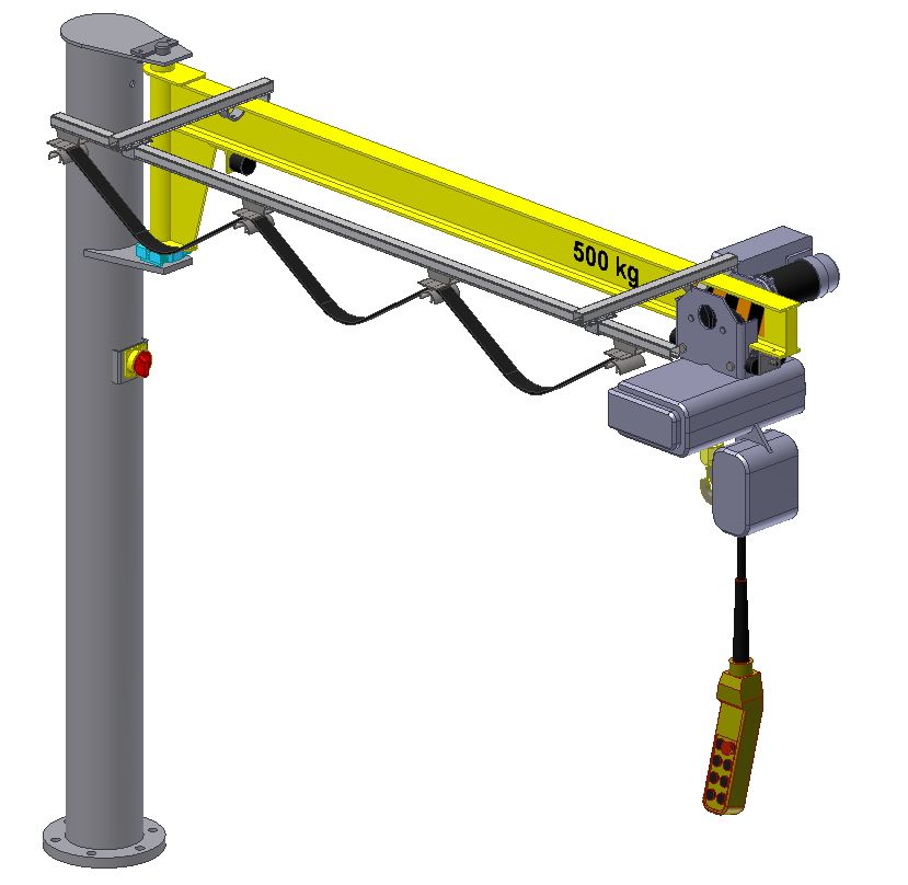
Table of contents                                                Page

Introduction

Part A – Operating instructions

   1.    Information on intended use                              A1
   2.    Usage limits                                             A2
   3.    Warning of improper use                                  A2
   4.    Description of dangers and warning of remaining risks    A4
   5.    Operation of the crane                                   A5
   5.1   Control elements                                         A5
   5.1.1 Power supply switch                                      A5
   5.1.2 Control switch                                           A5
   5.1.3 Crane switch / EMERGENCY Stop                            A6
   5.1.4 Locking device of boom                                   A6
   5.2   Operational elements                                     A7
   5.2.1 Stops for limitation of cross travel motion              A7
   5.2.2 Slewing brake for adjustment of the stiffness            A7
   5.2.3 Stops for limitation of slewing                          A8
   6.    Commissioning                                            A9
   7.    Decommissioning                                          A9
   7.1   Emergency situation                                      A10
   7.2   Danger to steadiness and operating reliability           A10
   7.3   Closedown                                                A10
   7.4   Disposal                                                 A11
   8.    Non permitted use – Ban on operation                     A11
   9.    Security advices                                         A11
   9.1   Responsibility of operating company                      A12
   9.2   Working environment                                      A12
   9.3   Choice of personnel and personnel’s qualification        A13
   9.4   Security advices to operating phases                     A13
   9.4.1 Transport and Storage                                    A13
   9.4.2 Normal operation                                         A14
   9.4.3 Maintenance works                                        A14
   9.4.4 Welding works on cranes                                  A15
   9.5   Advices to special types of risks                        A15
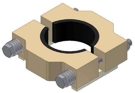
Table of contents                                 Page

   10.    Maintenance                              A16
   10.1   General information                      A16

Part B – Assembly instructions

   11.    Important requirements                   B1
   11.1   Welding works on cranes                  B1
   11.2   General assembly advices                 B2
   12.    Overview of crane                        B3
   12.1   Types of anchorage                       B4
   12.2   Equipment of the crane                   B5
   12.3   Marking on crane                         B5
   13.    Assembly crane pillar                    B6
   14.    Assembly boom                            B8
   15.    Assembly equipment                       B9
   15.1   Assembly hoisting gear                   B9
   15.2   Assembly cross travel stop               B10
   15.3   Assembly slewing brake                   B11
   15.4   Assembly slewing stops                   B11
   15.5   Assembly locking of boom                 B13
   16.    Assembly electricity                     B14
   16.1   Assembly basic electricity               B15
   16.2   Assembly power supply switch             B15
   16.3   Assembly grounding unit on boom          B16
   16.4   Power supply round cable                 B17
   16.5   Power supply trailing cable              B18
   17.    Information on fine adjustment           B19
   18.    Start of operation                       B20
   19.    Safety distances to slewing jib crane    B21
   20.    Additions and notes                      B22

Part C – Annex

   A      Dimension sheet
   B      Spare parts list
   C      Declaration of Conformity
   D      Declaration of Incorporation
Introduction

This document must be read by personnel in charge before the assembly and the initial operation as
well as before maintenance works. Provided that the complete instruction manual in not available, the
manufacturer shall be contacted. If required, the operating company shall translate the instruction
manual to user’s language. A safe operation and and a long fatigue life can be only ensured with a
proper use of the crane.

This instruction manual is intented for the use of slewing jib cranes with booms which can only be
slewed manually.

A hoisting gear can be assembled on a crane boom solidly or with a carriage, which does not exceed,
according to data sheet, the maximum permissible values for load bearing capacity, dead weight, as
well as lifting and cross travel speed and has a rated capacity limiter. For reasons of steadiness, the
crane can not lift from the floor, according to data sheet, more than 1.4 times the lifting capacity of the
crane. During the operation, the maximum permissible lifting load is limited to the nominal load,
according to the marked load bearing capacity. Higher loads are forbidden.

In the European Union, the legislators demand from the operators that instruction manuals shall be
always available and must be communicated to all users. In the Federal Republic of Germany it is
necessary to attach additionally a summary of the Accidents Prevention Regulations BGV D6 with the
essential security advices in a good visible manner directly on the work station of the crane operator.

Operators of crane units as well as the maintenance personnel must have knowledge of the
regulations and rules applying for this. Those are in the Federal Republic of Germany in particular:

        -   Accidents Prevention Regulations Cranes BGV D6
        -   Accidents Prevention Regulations Winches, Hoist and Traction Machines BGV D8
        -   BGR      500     –    Load     suspension      device     at    hoisting    gear     operation
Part A – Operating instructions

   1. Information on intended use
          -    The operator shall catch up on the intended use of the crane before start up. Improper
               use is forbidden.
          -    The crane may be only started up, when the assembly and the equipments comply
               with the valid regulations. (Declaration of Conformity is available, CE- mark is
               attached, acceptance inspection or regular inspection is visible on the test seal and
               still valid)
          -    The crane must be only assembled in an appropriate working environment. An
               accident-proof operation must be ensured.
          -    The assembly must be executed perpendiculary on a floor which is permanently
               capable of bearing, plane, vibration- and oscilliation-free.
          -    In the Federal Republic of Germany, only persons who meet the requirements
               according to UVV (accident prevention regulations) BGV D6 §29 can be appointed as
               crane operators.
          -    The application and the use of the crane are permitted according to classification in
               hoisting class and loading group according DIN 15018 (see information in test book).
          -    The slewing jib crane is intended to lift and drive (in each case power-operated or
               manually) loads on the boom using a hoisting gear. The slewing of the boom may be
               only executed manually, whereby the load must be guided by another person.
          -    Only hoisting gears which have a dead weight that does not exceed the limiting value,
               according to dimensions table [Annex A], may be used on the lifting arm to lift and
               drive loads.*
          -    The maximum permissible lifting speed of hoisting gears on the crane is 8.0 m/min. *
          -    The maximum permissible driving speed of power-operated trolley gears is
               20.0 m/min*
          -    Only hoisting gears with an effective rated capacity limiter (e.g. safety clutch) may be
               used.
          -    The slewing jib crane is designed for a temperature range between –10°C and +40°C.
          -    Only slewing jib cranes with additional mark “F” in their type designation are designed
               for an outside operation and can be operated till wind force 4, provided that the
               operating instructions are observed.
          -    Only slewing jib cranes with the additional mark “ex” in their type designation are
               designed for the operation in potentially explosive areas and can be used in the
               respective area according to their marking on the device and in the test book.
          -    Under operating conditions above the corrosion-protection class C2 or in the
               environment of aggressive mediums, special models are required.
          *) If higher values are permitted, thanks to special designs, they are recorded by the manufacturer in the
          additional data sheet. The additional data sheet is a component of the test book.

                                                       - A1 -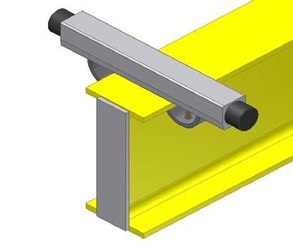
2. Usage limits

The use of slewing cranes is limited by the number of load alternations (frequency), the load spectrum
(load distribution) as well as by the design (execution) of the crane. The use of the crane outside of
the intended range can result in dangers to and damages on the crane.

Characteristic usage limits are:
       -    Higher dynamic load:
            Use of hoisting gears and load suspension devices, which require a higher classification
            into loading group and hoisting class, according to DIN 15018, as designated in the test
            book of the crane, e.g. during grab or magnet operation.
       -    Tendency to fractures of brittle materials, e.g. glass panels
            The boom bounces because of the elastic deflection. A gentle set-down is, according to
            the self-supporting length (column + boom), only possible to a limited extend.
       -    Operation at temperatures under -10°C and over +40°C
       -    Use under extreme ambience conditions, e.g. smelting furnances, acid baths and areas
            with strong vibrations.
       -    Actions which influence the static of the crane and its stability, e.g. extensions or
            shortenings of the boom or the column, modifications of attachments, modification of the
            load bearing capacity, subsequent installation of a hoisting gear, bigger or heavyer as
            intended or unapproved welding works.

    3. Warning of improper use

                  The following use of the crane is forbidden. A nonobservance can
                  result in risks for the operator and its environment as well as
                  damages on the crane structure.

            a. The use of a crane which is assembled improperly or an equipped crane without
                  manufacturer’s certifications (Declaration of Conformity, CE mark) or test badge.
            b. The use of a crane which is clearly damaged or defective, maybe also ignoring the
                  blocking and prohibition signs.
            c. Transport of unpermitted loads, such as passenger transportation, transport of fused
                  materials, transport of loads which are heavyer than the permitted load bearing
                  capacity of the crane
            d. Stay under suspended loads
            e. Diagonal pulling, trailing or sliding of loads
            f.    If not perpendicular under the hook or if hoisting gear “Open” – inching operation of
                  the hoisting gear – then release of uncontrolled movements of the boom or the
                  hoisting gear by fixing the load, swing up of the boom by operation of the hoisting gear
                  or interventions on the suspended load

            g. Loose of stucked loads, removal -ofA2
                                                   covers
                                                     -    of containers under residual vacuum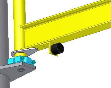
h. Slewing of the boom by pulling the control switch
i.   Welding works on suspended loads
j.   Lifted loads – must not be exceeded by additional load, must be set-down during a
     stoppage of the transport process, must not rest in the suspended position if they are
     unattended, must not tilt or knock over into the load cable because of a movement of
     the center of gravity.
k. During a use on the open air ground only such loads (dead weight, geometry, surface)
     may be used, which may be reasonably controlled by the user with the available
     means under the respective wind forces.
l.   Hooking of the crane hook in loads of fixed points and “tightening” of the load-carrier
     for the protection against unintentional movements.
m. Unpermissible high operating heights or operating distances – the crane operator
     must be able to operate the manual operated crane in every position in a save
     manner and to slow the load down.
n. Uncontrolled drive to final positions with a high manual speed
o. Improper anchoring or fastening of the crane, in particular with anchor bolts in the
     bottom flange holes on the column tube
p. Additions not intended or authorised by the manufacturer or design modifications on
     the crane
q. Fitting or mounting to air, water or landcrafts or other moveable machines not intended
     or authorised by the manufacturer. (also cranes)

     The slewing jib crane is not designed for continuous operation (continuous
     load changes in automatic processes).

                                     - A3 -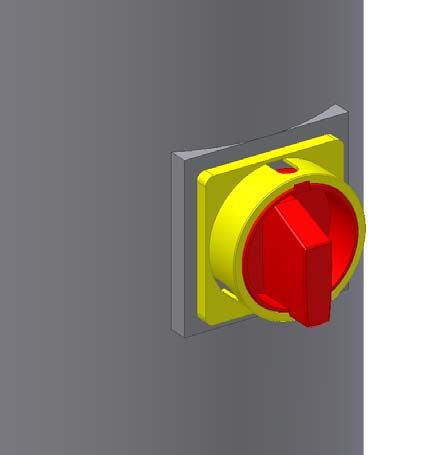
4. Description of dangers and warning of remaining risks
List of dangers according to EN 14121-1 for slewing cranes
N° Danger potentials Danger Solution / Warning
1 Mechanical dangers
1.1 Crushing of operator / of third persons by the load Observe safety distances ,
Observe swing of the load and braking distances
of operator by the boom Observe safety distances
Attach stops
of operator by boundaries on the final positions Observe safety distances
(arrestors) Observe operating instructions
Mark danger areas
of operator / foot by the load Observe safety distances,
Observe swing of the load,
Keep passing places free
1.2 Shearing of operator / hand by the boom, column, wall, Observe safety distances
support Observe operation instructions
Mark danger areas
1.3 Impact of user by swing of the load Observe safety distances
of operator / third persons by the boom Observe safety distances,
Warnings on the boom
of operator / third persons by unexpected / Use additional attachments (slewing brake, adjustment device of
unintended start boom)
Observe safety distances
Observe operation instructions
1.4 Fall down of pieces of operator / third persons by the load Observe safety distances
of operator by unintended operation Observe safety distance,
Observe operating instructions
1.5 Stability of operator by underground floor / wall / slab Leave danger area,
If possible, lower the load immediately,
Stop the crane,
Only dispose the load on sufficiently sustainable underground
1.6 Stumble and falling of operator / third persons Keep operation ways free, safeguard tripping points if necessary
Ensure sufficient stability,
Warnings in the working area
2. Electric dangers
2.1 Electric shock of operator by a damaged coating of electric Stop operation,
conductors Switch power off,
Replace defective lines
2.2 Error on power supply, functional disorder of of operator / third persons Activate emergency stop and
the control system Start measures for fault clearance by a qualified person
4. Noise dangers
4.1 Discomfort, stress, failure of the voice of operator / third persons by warn parts or grinding Stop operation,
communication surfaces Fix the error
7. Material / substance dangers
7.1 Operating supply items (oils, greases, of operator /third persons / environment by the See special operating instructions manual for hoisting gears and
lubricants) hoisting gear drives
7.2 Fire and explosion of operator / third persons by electrical operated Use only cranes designed for outside areas
crane Observe device categories and zone classification according to the
document on explosion protection of the operating company
8. Ergonomic dangers
8.1 Inadequate local illumination of operator / third persons Ensure adequate illumination
8.2 Human error of operator Training
9. Dangers by operational environment
9.1 Lightning of operator / load Stop operation immediately,
Lower the load immediately,
Stop the crane
9.2 Wind of operator / third persons by an uncontrolled drift of Stop operation immediately,
the load If possible, lower the load immediately,
Stop the crane
9.3 Frost of operator by unexpected crane movements and Observe temperature range
starts
9.4 Exterior effect of operator by e.g. other means of transportation Observe crane, load and environment attentively
10. Combination of dangers
10.1 Failure or incorrect arrangement of protective of operator Take measures to reduce the danger potential
measures
10.2 Start and stopping device of operator by control switch Push emergency stop in the case of a defective control switch,
switch the machine neutral, replace parts
10.3 Security symbols / signals of operator by faulty labelling Hold labelling readable
Information and warning devices
10.4 Turn-off devices of power supply of operator by power supply switch and emergency Check on functioning before starting the work
stop
10.5 Emergency measures working area / operating company Push emergency stop, if the danger can be reduced with this action
10.6 Equipment for a safe adjustment and / or of operator Prior to all maintenance and repair works on the crane, lock the
maintenance power supply switch up in position “Off”
10.7 Failure assembly of operator Stop operation, fix the errors
Table 1
- A4 -5. Operation of the crane / operation modes / intervention processes of the operating person
Basis for the operation of the crane are the operating manuals for crane and hoisting gear as well as the
UVV cranes (BGV D6). These documents shall be displayed on place by the operating company of the
machine. These instructions, advices and directives shall be observed.
5.1 Control elements
5.1.1 Power supply switch
The power supply switch (drawing 3) is located on the
crane column. Normally, it is attached into the column
tube, so that only the lockable operation device is
accessable for the operator. It has 2 settings:
- “0“ the contacts are opened, the crane is
currentless
- “1“ power supply on crane available
The power supply switch cuts the crane from the power
supply (all phases). In “0“ position it is possible to secure
the turn knob by hinging a padlock.
5.1.4 Control switch
Drawing 3
The hoisting gear is operated via the control switch (drawing 4). Normally,
the control switch is located on the hoisting gear and connected with it via
the control line. The control line serves for the signal transmission from the
control switch to the control system of the crane and has a strain relief which
avoids a tearing due to the dead weight. The control switch must NOT be
used to slew the boom.
At the trim line “ideal controlling” the control switch is not attached on the
hoisting gear but is located on a control trailer, which is movable in a
separate sliding rail on the boom, independently of the hoisting gear.
The control switch is equipped with operation elements to control the crane
movements as well as with a crane switch (EMERGENCY Stop).
For further function descriptions see operating manual of the hoisting gear.
Drawing 4
5.1.4 Crane switch / EMERGENCY Stop
The red marked crane switch (EMERGENCY Stop) (Drawing 5) stops with operation
(pushing) all power-driven functions. By a short clockwise turning the red switch goes
back to its starting position and all functions are operational again.
Drawing 5
- A5 -Never operate the EMERGENCY Stop together with other operation element –
this could result in movements of the crane.
5.1.4 Locking device of the boom
(special equipment, serial at operation in oper-air ground)
The locking device of the boom (drawing 6) serves for the secure fixing of the boom in one or more fixed
positions of the slewing range. At cranes which are designed for the use on open-air ground, the locking
device of the boom serves for the wind bracing on one boom position minimum. The operation (Loosening /
Locking) is allowed till approx. wind force 4. Beyond that, very high operating forces occur and the drifting
boom is potential danger. For this reason, only loose the locking device if there is no danger of drifting
booms due to wind.
The operation takes place by pulling the
operating rod (A1) till the return stop (A2)
below the bearing plate is visible and the
locking bolt (A3) releases the boom (1). Now
the run-back of the locking pin (A3) is avoided
by a 90 degree turning of the operating rod
(A1). The boom can slew freely. If the boom
shall be locked, it shall be slewed manually to
a locking position till the locking bolt (A3) is
located under a drilling / locking strap (A5).
The locking of the bolt takes place in reverse
order.
Abb. 6
Drawing 6
- A6 -5.2 Operational elements
All stops are designed as EMERGENCY end stop and must not be arrived during normal operation. (see
also BGV D6 § 30).
5.2.1 Stops for limitation of cross travel motions
The pictured stops of cross travels are exemplary and can differ according to hoisting gear make.
Drawing 7
5.2.2 Slewing brake for adjustment of the stiffness
Drawing 8
As special equipment, the slewing brake (drawing 8) serves for the adjustment of the stiffness of the boom
(see mounting instructions paragraph 15.3). Slewing brakes are intended for cranes in closed halls.
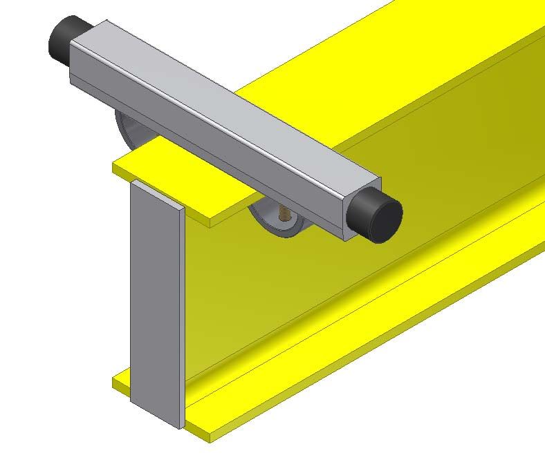
- A7 -5.2.3 Stops for limitation of slewing
According to installation size, crane equipments and intended use, they are a component of the crane
construction or the special equipment (take information from the order documents or the additional data list
in the test book of the crane).
Stops for limitation of slewing shall be employed to:
- avoid a crash of the crane boom or of pieces of the equipment assembled on the boom (hoisting
gear, power supply etc.) on the interference contours in the environment of the crane (e.g. walls,
supports, other cranes)
- limit the working area or the boom
- safe attachment parts against crashes on the crane column
Depending on the function 2 types of stops for limitation of slewing are differentiated:
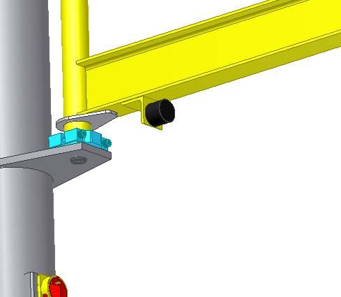
a) Stop for limitation of slewing with buffer rod for clamping on the boom (counter stops in the
environment of the crane)
Drawing 9
b) Stop for limitation of slewing for assembling on the crane basis (counter stop is the crane itself)
Drawing 10
All stops are designed as EMERGENCY end stop and must not be arrived during
normal operation. (see also BGV D6 § 30).
- A8 -6. Commissioning
- the statutory acceptance tests (according to UVV BGV D6 § 25) must have taken place before the
initial operation
- the crane must be evidently in a safe and functional condition
- the operator must have read and understood the operating manual
Steps before commissioning
- visual inspection that all parts are free of external damages and reliably operating
- activate the power supply switch on the crane column
- unlock the EMERGENCY Stop button on the control panel
- loosen the locking (if existing on the crane)
- use boom and hoisting gear
Transport of loads
- Select adequate slinging means for the choosen load and the transport.
- Hinge the load hook and the boom above the load centre into the load or the slinging mean and
tighten the load cable carefully.
- Always lifting the load from the floor in fine motion. Use a faster lifting speed for the lifting to the
desired height not before the load is hanging safely.
- At manually operated cranes, all moves shall be realised by guiding the load or the load cable. The
crane operator must drive manually and partially power operated cranes so, that he is able to stop
the released travels and rotations without any danger.
EMERGENCY Stops (stops) must not be arrived non-braked.
- If a direct guiding of the load is impossible, additional guiding aids (e.g. ropes, chains or guiding
rods) shall be attached on the load, the load hook or the boom.
- Keep the transport process shortly and put the load in a safe position and completely down.
Hang the load hook out and bring it to a safe stand-by position.
7. Decommissioning
The crane shall be stopped at the end of work or longer stoppages of work as well as in cases of
recognized damages or occuring critical situations.
- Hoisting gear in standby position
- Push power supply switch to 0 condition
In cases of interruptions, shutdown or wind force >4, the booms of cranes in operation on open air ground
shall be locked by a serial locking in its standby position.
- A9 -7.1 Emergency situation
An emergency situation exists, if the crane movement does not stop or is impeded, e.g. by jamming or
catching loads.
Acting in case of emergency situations
- Activate the existing EMERGENCY – STOP devices on the control switch or the power
supply switch!
- Inform immediately the competent authorities of the company!
- Safeguard the danger area!
7.2 Danger to steadiness and security of operation
The steadiness is not ensured:
- if there are cracks on welding seams of the crane column or the boom,
- if there are loosen attachments or screw joints,
- if buildings – floor, wall, slab, supports, frames can not absorb the fet forces anymore
The security of operation is not ensured:
- in case of a high wear of components; breakage, cracks, deformation, corrosion of load bearing
components on the crane or in load bearing means (ropes, chains, hooks),
- in case of a damage on electrical equipment,
- if loads can not be hold (rated capacity limiter and/or brakes faulty or worn)
- if there are damaged functional components (stops for limitation of cross travel motion, slewing
limitation stops, etc.),
- in case of a overload of the crane by exceeding the permissible lifting capacity or e.g. by inching
the control switch frequently during the lifting or lowering movement, which results in a higher
dynamic pressure. (“inching operation is forbidden!“)
7.3 Closedown
A closedown of the crane shall be carried out in case of:
- damages or wear till the repair is carried out
- achievement of the theoretic remaining service life,
- absence of the required maintenance and quality inspections (see inspection plate on crane)
After the closedown another use of the crane must be excluded, e.g. by locking the power supply switch in
“Off” condition with a padlock.
- A10 -7.4. Disposal
After the end of the operation period or irreparable damages on the crane the same must be shut down and
disposed as steel scrap. The disassembly shall be only executed by a competent person. Electric
components on the crane shall be disposed environmentally friendly.
8. Non permitted use – Ban on operation
No Transportation of persons!
No Transport of fused materials!
No Diagonal pulling, trailing and loose of stucked loads!
No Slewing of loads or moving of the crab by pulling the control switch!
No Stay in danger area during the crane operation!
No Stay under suspended loads!
No Use of damaged load bearing mediums and load handling devices!
No Transport of unsecured loads!
No Loads which exceed the indicated load bearing capacity and the classification!
No Unintentional crane movements due to faulty operation, unsufficient braking
efficiency!
No Load lifting by inching operation or swinging up of the boom as a result of external
influences!
No Rest of the loads in suspended positions without control!
No Welding works on suspended loads!
No Fixing of hoisting gear or boom by insertion of the hook and “lifting opened” so that
the system is permanently loaded
Please note: Note on paragraph 3. Warning of improper use
9. Security advices
The slewing jib crane is designed and constructed according to the state of technology / the valid safety
requirements*. It meets the demands of the EC Machinery Directive. Using the crane as intended the
dangers to life and limb of the operator and third persons as well as of the material values are low. Thereby
a sensible handling with regard to security and dangers according to the operating manual of the crane and
the hoisting gear is assumed.
The crane must be stopped immediately if defects or irregularities are determined at the function. The
safety distances shall be observed obligatory according to the valid directives BGV D6 §11.
*) At the date of placing on the market
- A11 -9.1 Responsibility of the operating company
- Right selection and load of the crane
- Sure function and fixation on crane and loads
- Sure operating condition of the crane
- Sure operation and use by the operating personnel
- Initiate required acceptance tests and recurring inspections
You, as operating company, are responsible for the acceptance of the crane and for recurring inspections
(maintenance) according to BGV D6 and BGV D8.
All persons who are authorised with the operation and maintenance of this crane must have read carefully
and understood this operation manual. Any non-compliance and act in opposition can result in accidents
and dangers.
Additional to the operation manual, the operating company of crane units must also observe and instruct
the general laws and provisions for the prevention of accidents and to the environmental protection.
The following protection devices exist on the slewing jib crane:
1. Stops for limitation of cross travel motion on boom (emergency stop device)
2. Slewing limitation stop (partial special equipment)
3. Protective conductor of boom and crane column (only cranes with electric equipment)
Due to special local conditions or cases of operations, situations could exist or appear, which are not
considered in this operating manual. In such cases the required measures for the security of the operator
shall be decided and initiated.
The operating manual shall be completed by the operating company with instructions regarding work
organisation, working processes, authorised personnel, obligations of supervision and to inform etc.
9.2 Working environments
The slewing jib cranes are remote-controlled cranes. That results, that the operator must know the working
environment, especially with regard to obstacles in working and transport area, possible tripping points and
existing control elements and safety devices (e.g. emergency stop switch).
Release and swing of loads are forbidden. Manual operated cranes shall be guided on the load hook
and/or the load. Safety distances to stacked material must be observed. The guiding of loads on ramps,
chambers or towers is dangerous. There is a risk of falling. Here, the operating company arranges
additional safety measures.
- A12 -9.3 Choice of personnel and personnels qualification
According to UVV BGV D6 § 29 the following directive applies:
“To operate and maintain the crane independently the operating company may only authorise persons,
- who are physically and mentally suitable
- who are likely to fullfill their tasks reliable
- who are instructed in driving and maintain the crane and have demonstanted their competence
- who have reached 18 years of age.
Only adequate qualified personnel may be deployed for repairs and maintenance works.
Works on electric equipment may only be executed by an authorised electrician or by instructed personnel
and under the direction and supervision of an authorised electrician.”
9.4 Security advices for operating phases
9.4.1 Transport and storage
The slewing jib cranes must be transported and stored as demounted components. Hereby the essential
components, crane column and boom, are not stable due to their geometry. For this purpose the
components are provided ex works with adequate disposable transport aids (pallets, square timbers,
stretch tapes). This transport aids shall not be removed before the assembly. During the transport, the
packing units shall be secured on the transport mean against slipping and tilting (e.g. load restraint
assemblies in case of delivery with truck).
In case of a later assembly of the crane the components crane column and boom shall be put for transport
and storage on adequate stable transport aids and shall be additionally secured against tilting, rolling and
slipping with load restraint assemblies and support blocks.
During the storage, the components should be secured against atmospheric influences. The storage should
take place between –20°C and +45°C.
9.4.2 Normal operation
Emissions
Noise emission: At motor driven hoisting gears the noise emissions vary from low up to high noise levels.
Please read the information in manufacturer’s operating manual of hoisting gear for advices on emissions
of hoisting gears. Other emissions are not known till this day.
- A13 -Observe the following security advices during the daily operation:
- Only work with a safe and functional crane. All EMERGENCY Stop devices and control
elements must be available and meet the requirements.
- Only work with the crane if you know the limits of the machine (load bearing capacity, allowd
speeds, working areas) and you are familiar with the operation. (function of control elements
and safety devices)
- Refrain from actions which endanger the stability of the crane.
- Ensure a safe working environment and refrain from risky actions.
- Check the crane minimum once per shift for externally visible defects and faults.
- Stop the crane in case of visible faults or abruptly changed operating performance (see
operating manual chapter 7) and act according to operating manual point 9.4.3.
9.4.3 Maintenance works
Observe the following security advices during works on the crane:
- The maintenance means measures for maintenance, inspection and repairs. These works may
only be executed by qualified personnel.
- The adjustment and maintenance works as well as inspection intervals, including information
on replacement of components, specified in this operating manual, shall be observed.
- The crane unit shall be stopped during all works and secured against unintentional or
unauthorised start. (lock power supply switch with padlock and/or attach warning plate on the
switch) If necessary, the working area shall be protected.
- Ensure that the electric components and cables are dead-voltage before working on electrical
installations and facilities of the crane unit.
- During the assembly, single parts and bigger components must be safety attached with
adequate hoisting gears. Do not stay under suspended loads.
- During assembly works over 1.80 m an adequate access method (ladders, work scaffoldings,
platforms for lifting persons) shall be used and a fall protection shall be worn. Do not use parts
of the crane as climbing aids.
- If a temporarly disassembly of safety devices is necessary, they shall be reattached before
commissioning.
- Check all screw fittings on the crane for tight hold during maintenance works.
- After finishing all works on the gear the operating company may release the gear not before
inspection to proper condition. If necessary, a competent person or authorised expert shall be
commissioned with it.
- A14 -9.4.4 Welding works on cranes
You may only weld on cranes if:
- it is required and described in the assembly instructions
- the manufacturer has authorised this welding works
- all requirements for the welding are complied with.
Requirements for welding works on cranes:
- obtain a written approval of the operating company (hot-work permit)
- observe UVV BGV D1 " welding, cutting and allied processes "
- observe VDI – Directive 2382 / 1990 – 08 " Maintenance of crane units; welding, stitching,
flame cutting, drilling"
- qualification of manufacturer class E according to DIN 18800-7:2002 (steel structures) required
- valid welder’s performance qualification according to DIN EN 287-1 of the working welder
required
9.5 Advices to special types of risks
Dangers by crushing hazard at the slewing jib crane
During operation:
- by swinging or falling loads
- by a run over of indoor cranes
- by moving crane parts during the arrangement of parts of the construction in working and
transportation area
During maintenance:
- by unlocked, slewing booms
- by unsufficient stability of the crane
Dangers by electric power (electric shock)
- faulty electric connections
- Parts of the construction which are energised because of defect coating
- unsufficient distance to aerial cables or open current bars of indoor cranes
- during maintenance works on energised parts
Dangers due to the hoisting gear
- due to unintended movements due to errors or defects on the electric installation or
controller (e.g. independently running motor movements or incorrect rotating direction of
drives)
- A15 -10. Maintenance
Maintenance works on the trestle crane serve for the maintenance of the operating reliability and the
functionality and increase the fatigue life of the machine. The maintenance must be carried out regulary
and by experienced qualified companies and/or qualified persons according to BGV D8 §23 and BGV D6
§26.
10.1 General information
Even though the crane is extensively maintenance free, the components which are subject to a wear must
be checked regulary.
With an intended assembly and use of the crane, the service life of any wear parts amounts normally to 10
years. In case of a stress above average as a result of external influences the service life can be
shortened, so that the wear parts must be replaced early.
Components which are essential for a sure operation must be checked per working day
and before every use.
Inspection interval: The inspection intervals are fixed on 12 months for all parts according to the design
of the crane for the entire service life.
The following components must be checked regulary:
Daily inspection / before commissioning – X
Inspection every 12 months – O
Components Pos. N° Check for Measures
Wear parts:
Buffer stops for cross Replace the buffers,
travel motions
51 Functionality / wear
If necessary, correct fitting and fixation X
Stop buffer for slewing Replace the buffers,
stops
51 Functionality / wear
If necessary, correct fitting and fixation O
Slide ring 21 Wear Replace slide ring O
Wear of the brake pad, Replace the brake pads
Slewing brake 4
Pretension of the disc springs Replace the disc springs O
DU bushes 50 Too much clearance Replace the DU bushes O
Breaking of the spring, Replace spring
Locking of boom
Wear of the locking pins Replace locking pins X
Electrical
components:
State of cables and Stop the crane and repair defective installation by
electric lines
Correct operation and coating
a qualified electrician O
State of main switch 224
Correct operation and locking Stop the crane and repair by a qualified
and/or
capability electrician X
301
- A16 -Components Pos. N° Check for Measures
Other components:
Correct marking of load
Marking of load bearing
capacity
150 bearing capacity on crane and Attach right marking X
hoisting gear
Check of corrosion
protection
Defects Refit corrosion protection O
Tight fitting and existing
Screw joints / Tighten the screw joints with dynamometric key,
Attachments
locking devices /
add locking devices O
Tightening torque
Stop the crane and inform qualified personnel for
Weld seams Cracks (especially foot flange)
repair O
Table 2
Important advices:
- The boom shall be locked against unintentional motions
- Only execute maintenance and repair work on the unloaded crane
- Switch off and lock the main switch
- Observe instructions of accident prevention regulations
- Maintenance work shall be documented in the inspection records (according to BGV-
D6 §27)
- After end of service life of the hoisting gear a general overhaul shall be executed
- Manufacturer’s operating manuals for the hoisting gears shall be observed
- A17 -Part B – Assembly Instructions
11. Important requirements
These assembly instructions apply to the installation of a slewing jib crane.
Please read the operating manual before starting the assembly. The drawings stated in the
manual are exemplary and may differ from the model provided.
The following safety instructions shall be observed during a proper assembly:
For assembly personnel
- The assembly work must be executed by qualified personnel only and shall be coordinated
between the operator and the operating company.
- The assembly personnel shall be protected against local dangers during the assembly of
the column and the boom.
- Auxiliary material shall be used in a manner that danger to person due to unintended use
will be prevented.
- Only adequate and certified tools shall be used during the assembly of the slewing jib
crane.
- The work steps described below shall be observed.
- The stay under suspended loads is forbidden.
- The unit shall be activated considering the electrotechnical instructions and only
assembled in zero potential condition.
For assembly site
- The working and danger area shall be sufficiently secured.
- Customer specific instructions shall be observed
- Hoisting gears and auxiliary material, adequate for the assembly, must be available,
certified and in proper state and shall be used according to the intended use.
11.1 Welding works on cranes
You only may weld on cranes if:
- It is required and described in the assembly instructions
- We, as manufacturer, have allowed the welding works
- All requirements are complied with (see 9.4.4)
- B1 -11.2 General assembly advices
- Slewing cranes only operate correctly if they are assembled according to this manual.
- Statutory tests and maintenances must be executed at regular intervals.
- Before every assembly, the installation conditions on site and the crane and installation
height due to the design shall be checked. The statutory safety distances shall be
observed.
- Only slewing jib cranes with additional mark “F” in their type designation are designed for
an outside operation and shall be assembled and operated there.
- Only slewing jib cranes with the additional mark “ex” in their type designation are designed
for the operation in potentially explosive areas.
- For the included hoisting gears, the respective operating manuals of the manufacturer shall
be observed.
- After finishing the assembly, execute all crane functions carefully and check the proper
function.
- Operating instructions shall be attached on the crane in a clearly legible manner.
- At power operated cranes and all cranes with a load bearing capacity higher than 1000 kg,
checks must be executed according to UVV- Cranes BGV D6 §25 before initial operation.
- All checks shall be executed according to §19 of IEC 60204-32.
- B2 -12. Overview of crane
Constructional design
Axle support Swivel axis Power supply
Slewing stops Cross travel buffers
Boom
Hoisting gear
Slewing brake
Main switch
Control device
Foot flange
Power supply
Round cable Trailing cable Ideal control system
Possible anchorages
Foundation anchorage Bolt anchorage Mobile unit
(Intermediate (displaceable)
base plate)
Drawing 11
- B3 -12.1 Types of anchorage
Additionally, it is possible to anchor the crane with a base plate or a foot flange on an adequate
substructure, for example:
- On a floor slab using straight fitting and counter plates
- On a steel construction with adequate screw or weld joint
The requirements on this substructure result from the individual technical parameters (loads and moments),
as well as from the general requirements on the anchorage of the crane.
For effective loads on the on site anchorage see the purchase order documents or consult the
manufacturer. Information of general dimension and data sheets only apply to standard designs with foot
flange and till the construction height specified there.
Requirements on the foundation – Check before assembly!
- Foundation must be sufficiently hardened (clearance through the supervising company)
- Foundation shall be checked on compliance with provided outer dimensions
- Position, number and arrangement of the anchor bolts shall be checked according to
dimension sheet
- Number of the drilled holes in the foot flange must conform to the anchor bolts
- Diameter and screw thread of the anchor bolts shall be checked
Requirements on the bolt plate – Check before assembly!
- Evenness and straightness of the floor
- No grooves in the area of the bolt plate and respect of the edge distances according to the
admission requirements for anchor bolts (see assembly instructions “Standard and
intermediate base plates for the bolt anchorage“)
- According to the processing guidelines of anchors, the temperature of the anchorage
basement must be between +5°C and +25°C
- The minimum requirement on the concrete quality and the contrete thickness of the
anchorage basement shall be checked according to the admission requirements and
documented in the assembly record
Requirements on the supporting structure on site:
- Must be free of oscillation and vibration
- Must be able to take load and stiff
- Open profiles (such as I profiles) are flexible in torsion and so they must be sufficiently
dimensioned and require, if necessary, a bracing to the box girder
- The joint and supporting surfaces must be even and horizontal
- B4 -12.2 Equipment of the crane
Standard equipment Special equipment
• Slewing brake
• Crane column with foot flange
• Locking device of boom (standard for outside
• Boom
operation)
• Swivel axis
• Slewing stops
• Cross travel buffers
• Hoisting gear
• Equipment and small
• Main switch
components
• Power supply
Table 3
12.3 Marking on the crane
Mark of the load bearing capacity (on both sides)
The following markings must be attached on
the crane:
- CE Mark
Warning mark (on both sides)
- Mark of the load bearing capacity
- Warning mark
- Type plate
Operating instruction
- Operating instruction
Main switch
Type plate
- Main switch
CE Mark
If these markings do not exist on the crane,
they must be amended.
(see annex B – spare parts list)
Drawing 13
- B5 -13. Assembly crane column
Firstly, deposit the crane column along with the desired position and check the following points:
Is it enough hardened?
Is the grommet inserted and the feed
- Foundation (if existing) Æ
cable long enough – cable de-
energised?
Check diameter and number of drilling
- Foot flange of crane column Æ
hole!
- Anchor bolts Æ Distance and number
Diameter M
Functioning of the screw thread
Straigthness
Please note introduction “FOUNDATIONS – planning and building“
In case that the anchor bolts are not in the prescribed state, the number and the distances
are not correct or the screw thread is damaged, the crane column must not be assembled.
A sufficient stability is not ensured anymore. The occurred faults shall be fixed before
beginning of the assembly.
Foundation
Grommet
Drawing 14
Remove the hexagonal nut (F2) and the flat washer (F1) after the inspection. Now you can remove the
former plate (F3). This former plate can be disposed (Steel scrap).
Adjust the lock nut so that it is flush with the ground (hall floor). The foot flange of the crane column should
be flush with the hall floor.
- B6 -Power supply
Drawing 15
With an adequate hoisting gear and slinging mean, lift the crane column carefully in a vertical position.
Now, guide the power supply through the column till the hole for the main switch and draw it through the
hole.
Set the column carefully down and pay attention to an insertion of the anchor bolts as gentle as possible to
avoid damages on the threaded end. Fix the column with hexagonal nut (F6), flat washer (F5) and counter
nut (F7).
Security advice: Observe tightening torques for hexagonal nut (see table 5)!
With a water level, check on several points on the diameter of the swivel axis if it is
perpendicular. Check in the area of the lower console if it is horizontal.
The adjustment takes place by loosing and tightening (F4) and (F6) carefully.
The fine adjustment of the crane must take place after assembly of the boom and the hoisting gear as well
as with completely assembled equipment and in hardened foundation (see chapter 16.6)
Tightening torques for hexagonal nut
Dimension Tightening torques for hexagonal nut (F2)
M20 184 Nm
M27 470 Nm
M30 635 Nm
Table 5
- B7 -14. Assembly of the boom
The following parts are loosely enclosed for the assembly of the boom (1):
1x Swivel axis (20)
1x Safety plate (22)
2x Hexagon head screw (120)
4x Flat washer (121)
2x Hexagon nut (122)
1x Slide ring (21)
Clean the upper and lower sliding bearing (DU bush (100)) and remove heavy solings on mechanical parts.
The bearings are ex factory fitted to the boom tube and should not be disassembled.
Drawing 16
Assembly:
1. By loosing (120) to (122), disassemble the swivel axis (20) and the safety plate (22) from the crane
column. - Caution: Fall hazard of the swivel axis during the removing of the safety plate!
Keep these parts because they are needed later for the assembly of the boom.
2. Lift the boom (1) carefully. Make sure that the boom is protected against fall and is lifted
horizontally.
3. Move the boom laterally between the upper and the lower console of the slewing column (2) –
Caution! Higher risk of crushing!
4. Insert the slide ring (21) carefully between lower console and boom. Pay attention to the higher risk
of crushing!
5. Insert the pre-assembled slewing brake between the guide brackets on the lower bearing console
(only with special equipment “slewing brake“).
6. Guide the swivel axis (20) from below through the provided drilled hole of the lower console– slide
ring – swivelling tube – drillet hole of the upper console.
- B8 -7. Protect the swivel axis (20) against fall out, using the safety plate (22). Fix the safety plate with the
positions (120) to (122).
8. Slew the boom to all possible final positions, according to the local conditions, and check if the
boom stops in all positions. Should this not be the case, observe the possibilities of adjustment
(see chapter 17)
15. Assembly equipment
The supplementary equipment offered by us is the permitted equipment for the crane. We, as crane
manufacturer, adjust our equipment to the crane and certify the belonging in the inspection records on the
additional master data list. In addition, the crane is intended for the use with hoisting gears and load
handling devices which meet the national accident prevention regulations as well as the current EC
Machinery Directive. During the choice of the hoisting gears, the limitations according to chapter 1
(intended use) and the data sheets shall be observed.
15.1 Assembly hoisting gear
Review and decide in advance, if you pre-assemble the cross travel winch and the hoisting gear on outside
and hang it then into the boom of if the assembly of the hoisting gear should take place directly on the
boom. Assemble the hoisting gear and the travelling winch according to the individual instructions of the
respective manufacturer of hoisting gear. Ensure the correct adjustment of the bottom flange carriage to
the width of the mounting flange of the boom. Consider the clearance on the crab gauge provided by the
manufacturer of the hoisting gear.
Advice!
Observe the instructions of the manufacturer of hoisting gear!!!
Possible arrangements (in direction to the head of the
Component boom)
Left Centre Right
Chain box X
Hoisting gear normal design X
Carriage X
Control switch on hoisting gear X
Trailing cable X or X
Round cable X or X
Terminal box on boom
Arrangement according to the point where the power supply
Terminal box on carriage
is assembled
Terminal box on hoisting gear
Table 6
- B9 -15.2 Assembly cross travel stops
The inner cross travel stops are tightly connected ex works with the boom. The cross travel stop on the
head of the boom is removable. They are suitable as final position limitation for numerous cross travel
winches.
ADVICE: If the function of the cross travel stops of carriages delivered to you is not
ensured, universal cross travel stops in clamping design are available as special
equipment.
The following parts are loosely enclosed for the assembly of the cross travel stops:
1x Stop angle (23)
2x Rubber buffer (110)
2x Flat washer (111)
2x Hexagon nut (112)
2x Hexagon head screw (115)
4x Falt washer (116)
2x Hexagon nut (117)
Assembly: Drawing 17
1. Fix the stop angle (23) on the head of the boom using (115) to (117).
2. Fix the rubber buffer (110) on the stop angles using (111) and (112).
By starting the carriage, ensure the function of the cross travel stops after the
assembly.
CAUTION: Without cross travel stop on the head of the boom, the hoisting gear (with
load) moves from the boom Æ danger of fall down of the load!!!
- B10 -15.3 Assembly slewing brake
The slew brake (special equipment) serves for the adjustment of the slewing rate of the boom. The brake
shoes equipped with a brake pad can be pressed on the slewing column via a manually fine adjustable disc
spring packet and as a result they avoid, according to pretension, the overtravel of the boom.
40.3 40.11 40.1 40.10
40.12
40.1
40.3 40.11 40.2
Assembly: Drawing 18
1. Position the both blocks (40.1) with the distance pieces (40.2) downwards on the lower console of
the crane column between the guide plates intended for this purpose on the lower console of the
crane column.
2. Attach 10 disc springs (40.12) in each case (according to drawing 18) on the screws (40.11) and
connect the both blocks using the scews and nuts (40.10).
3. The braking effect is adjusted by tightening the nuts (40.10) uniformly.
Is case of the subsequent equipment of cranes with slewing brakes it is necessary to refit guide plates on
the lower bearing console. In this case, please observe the separately available assembly instructions.
15.4 Assembly slewing stops
The sleving stops serves for the limitation of the slewing motion (special equipment).
Slewing stops in weldable design are provided as all-purpose
fixed stops on the head of boom.
The stops consist in each case of a steel profile as well as of a
rubber buffer (41.10) with stay bolts and a flat washer (41.11)
and a hexagon nut (41.12) for the fixation. During the welding,
the rubber buffers shall be removed from the profile.
41.10, 41.11, 41.12
Drawing 19
- B11 -Slewing stops with buffer rod are provided for the assembly in
the area of the head of boom. For reasons of the optimum load
application the stops provided for clamping on the upper flange
or the end plate shall be
- Assembled max. 300 mm before end of boom
- Take effect perpendiculary on a fixed counterplot in the
environment of the crane
Drawing 20
Please review before assembly:
- Do you meet the requirements of welding on cranes?
- Allow the environmental conditions on assembly site a welding?
- Are all equipments, hoisting gears etc., relevant to define the slewing range, assembled on
the crane?
- Which interference contours in the environment of the crane shall be protected against
impact of the boom and how must the boom protected against impact?
- Decide on which point (Crane column or lower bearing plate) and in which position
(standing of lying) the universal stop must be welded to fulfil its function.
- In this connection, please take account to a maximum long weld seam (GSX design size 1-
3 minimum 75 mm, design size 4+5 minimum 120 mm).
Assembly:
1. In the area of the projected welded seam, remove locally the existing anti-corrosion
coating.
2. Attach the buffer and check the intended function – if necessary, adjust the position of the
buffer.
3. Completely weld the buffer on (hollow weld a=3mm (size 1 to 3) and/or a=4mm (size 4 and
5).
4. Check the function of the stops with and without load on the respective final positions of
cross travel.
5. Using the included correction colour, renew the anti-corrosion coating in the area of the
welded seam.
- B12 -15.5 Assembly locking of boom
The locking of the boom is intended for the fixation of the boom in one or more positions within the
swivelling range of the crane. At cranes for outdoor operation the locking is standard equipment and serves
for wind bracing (see also chapter 5.1.4)
The locking of the boom is pre-assembled ex works on the crane column.
During the installation of the crane and
assembly of the boom the locking of the boom
shall be adjusted in position “loosen” (control
rod A1 pulled and locked) to ensure a smooth
hanging in of the boom.
Check the locking for function after assembly
of the boom (see chapter 14) and, if
necessary, readjust the slewing bracket.
Drawing 21
During maintenance and repair works, it could be necessary to disassemble the locking to replace for
example the spiral spring. In this case the bolt (pos. A2 and A6 – called return stop) must be replaced and
the control rod can be pulled downwards out of the guide plates. Remove spring and flat washer carefully.
Caution – the return spring is under pre-tension.
The assembly proceeds in reverse order. Position the new spring (A4) and the new flat washer (A7)
between the plates and the control rod into the drilling holes of the guide plates. Lock it with bolt (A2 and
A6) and, after assembly, check locking for function.
- B13 -16. Assembly electricity
Standard electricity
Equipment:
• Rising main
• Main switch Basic electricity
• Grounding unit for swivel column + boom
• The power supply to the hoisting gear on the boom is ensured via round cable or trailing cable
Round cable power supply Trailing cable power supply
Drawing 22
• The hoisting gear is controlled via a control switch which is directly attached to the hoisting gear.
Safety instructions
In case of faulty electric power supplies there is the risk of an accident, maybe a danger for
life and limb is also possible. Never act without thinking, it is impossible to replace a human
life.
Only electricians may create electrical connections!
Observe the currently valid directives:
- UVV BGV D6
- DIN VDE 0100
- DIN EN 60204-32
- DIN VDE 0100-600
Observe the safety instructions:
- Power off
- Ensure zero potential
- Protect main switch against unauthorised switch-on (e.g. padlock)
- Pay attention to right tension and rotating direction.
In case of emergency, push the EMERGENCY BUTTON on the control swith or cut the
electric power on main switch off.
- B14 -You can also read