Speckle characterization in a cinematography projection configuration
←
→
Page content transcription
If your browser does not render page correctly, please read the page content below
Speckle characterization in a cinematography projection
                                                                               configuration
                                                                         Pierre Walczak1,∗ ,Xavier Hachair2 ,Stéphane Barland1
                                                             1
                                                                 Université Côte d’Azur, CNRS, Institut de Physique de Nice, Sophia Antipolis, France
                                                                       2
                                                                         BBright, Les Galaxies, 1st floor, 1 Square René Cassin, Rennes,France
arXiv:1803.07028v1 [physics.app-ph] 19 Mar 2018

                                                                                ∗
                                                                                  Corresponding author: pierre.walczak@inphyni.cnrs.fr
                                                                                                    March 20, 2018

                                                     Due to high exploitation costs and other environmental issues, it would be desirable
                                                  to phase out large cinema projection systems based on standard xenon lamps in favor of
                                                  laser based projection devices. Lasers provide longer lifetime, wider color gamut, smaller
                                                  extension and higher stability of light output. But the high degree of coherence of theses
                                                  sources also lead to the formation of granular structures, usually known as speckle. When
                                                  an imaging system is involved, as in the cinema projection case because of the capacity of
                                                  the human eye to form an image of the screen, we speak about subjective speckle. In order
                                                  to remove this spatial random pattern, different methods have been studied as temporal
                                                  and/or spatial coherence reduction. But most of them can’t be used in the context of
                                                  cinema projection because they don’t respect the cinematography projection standard. In
                                                  our work, we have studied the possibility to reduce the subjective speckle either by changing
                                                  the coherence of the light source or by studying the influence of the different elements
                                                  constituting the projection display and most importantly in the conditions imposed by
                                                  cinematography industry. Thanks to a lasers array formed by N independant semiconductor
                                                  lasers, we have measured the evolution of the subjective speckle contrast in function of the
                                                  number of sources. The resulting contrast discreases as a square root function and reach a
                                                  saturation level when a light pipe is used. This behavior is directly due to the caracteristic of
                                                  the light pipe which limit at its output the spatial coherence of the light source. Futhermore,
                                                  in a different configuration, we have studied the influence of diffusers and the magnification
                                                  of the projector zoom. It has been demonstrated that magnification plays an important
                                                  rôle on the speckle formation because it increases the coherence length determined by the
                                                  light pipe. On the contrary, the diffusers placed before the light pipe doesn’t change really
                                                  the amount of subjective speckle.

                                                  Introduction
                                                  The light source at the origine of the cinema projection consists to use discharge lamps as for exemple car-
                                                  bon arc bulbs for the first one and since 1940’s the Xenon lamps. The characteristics of those light sources
                                                  make the energy efficiency of projection systems low mainly because of the decomposition-recomposition
                                                  to the Red, Green, Blue (RGB) colors and the polarization effect. In addition these sources create images
                                                  with low color saturation (bad color gamut). These last decades, the evolution of laser technology is
                                                  found to be a nice successor to the standard light sources based on filament lamps. Lasers have the
                                                  advantage to be monochromatic, directional, linear polarized and coherent. The projection system based
                                                  on RGB lasers sources provide a higher color gamut, a higher energy efficiency and a better life time.
                                                  However, the main problem of these sources is to create the well-known phenomenon called speckle due
                                                  to the coherence of the lasers.
                                                      Speckle is unavoidably generated by interference when a scattered highly coherent wave, such as
                                                  lasers, is reflected by a random surface roughness, such as typical cinema screens. It is common to
                                                  differentiate objective and subjective speckle. Speckle patterns are called objective when any imaging
                                                  system is involved. The speckle distribution can then be measured directly on an imaging sensor without
optical lens. On the contrary, when an imaging system is involved to form the image of the screen on a
detector (camera or human retina), we speak about subjective speckle. It doesn’t exist a standardized
quantification of speckle patterns. The more using tool to quantify speckle is to calculate its contrast
value defined by the ratio of the standard deviation to the mean of the light intensity fluctuations.
When the contrast is unity, the fluctuations of intensity are strong and the probability density function
is exponential. The speckle is generally called as fully developped speckle [1] and it will be generated
when the surface roughness is comparable with or larger than the wavelength of the light source. On the
opposite, when the contrast is null, the fluctuations are very small and the speckle doesn’t exit no longer.
    The theory of speckle formation, its statistical properties, and methods of speckle reduction have
been studied thoroughly those last decades [1, 2]. Several schemes for the reduction of speckles have
been developped such as polarization diversity [1], wavelength and/or angular diversity [1, 3]. But the
most common method is a moving diffuser placed in the path of a laser beam. In this configuration,
the phase contribution in every point of the image is modified in function of time. It is possible to use
one or several diffusers [4], to introduce a vibration [5, 6, 7] or a rotation [5] of the diffusing element.
Moreover, many other methods exist, such as using a laser array [8], moving the observation screen [9],
scanning micromirrors [10, 11], diffractive optical elements [12, 13, 6], rotating light pipe [14] or vibrating
multimode optical bundle [15, 16]. Howevever, few of these methods can be applied in the specific
context of cinema laser projection. Indeed, this context introduces specific normative and technological
constraints. From the normative point of view, the light emitted by the projection system must satisfy
several criteria imposed by the Digital Cinema Initiatives (DCI), as for instance a typical value for the
luminance. From the technological point of view, the projection system must include a homogeneizing
element, whose image will be formed on an intensity modulation device (Digital Light Processor, CMOS,
...) before being finally projected onto the screen. Several types of homogeneizing devices can be used
(light pipe [17, 7], bi-convex aspheric lens [18], or lenslet integrator [6] as double-sided microlens array [19])
but in any case the zooming system following this device will finally project its output on the screen,
after application of a spatial intensity modulation corresponding to the scene content. This point is key,
as it implies that any speckle reduction device altering the spatial intensity or phase profile of the light
must be placed upstream from the homogeneizing device if optimal image quality is to be preserved. Here
we adress the formation of subjective speckle in model experiments which feature the key elements of
video projection devices. Specifically, we analyze the impact of the spatial coherence of the light source
in absence and presence of the required homogenizing elements (first section), the impact of diffusors
upstream the light pipe (second section) and that of the zooming system leading to suitable size of image
projection (third section).

Speckle modification by the source coherence control
In the first part of our study, we are concentrated on the laser source light and its spatial coherence
properties on the formation of the speckle. Then, we have placed as it is recommended for the cinema
projection condition a diffuser and a light pipe to study their impact on the speckle. In this section, we
are not in the standard illumination recommended by DCI but it is the only exception of our study.
    Fig. 1A shows a schematic representation of the experimental setup inplemented to study the influence
of the light source on the subjective speckle formation. The first part of the setup is common to all our
experiments detailled in this section. The light source is a VCSEL array with a thermal regulation and
a laser diode controller. The VCSEL array (Philips PLA1520-980) is a small-sized, infrared laser array
light source based on Philips proprietary Vertical Cavity Surface Emitting Laser (VCSEL) technology. It
consists of over 450 VCSELs emitting at 980nm with a typical power of 2W and a spectral width of 2nm.
After the source, the near field of the VCSEL array is formed thanks to a lens. At the near field plane,
an iris diaphgram allows to select the number of sources used to make the experiment. In this way, we
are able to select between 1 to 450 lasers as we can see on the Fig. 1A. So, we can analyse the subjective
speckle formed by the sum of N independant coherent sources where we can control the parameter N.
After the iris, we have performed three different experiments that we have known configuration 1, 2 and
3 in the Fig 1A.
    In the first configuration of the Fig. 1A, we have investigated directly the importance of the light
source on the speckle formation by projected the far field of the beam after the iris on a paper screen.
After reflection, we have recorded the subjective speckle on a camera (Allied Vision Mako G-419B NIR).
At typical operating current for all the lasers, the far field emission pattern is donut shape. We have
represented on the Fig. 1B a cross section of the far field in blue line. His shape is close to a gaussian
function. In order to estimate the speckle contrast, we have used the following procedure. We have
Figure 1: Illustration of the experimental setup and cross section of the far field experiment.
(A) We have represented the experimental setup. It is subdivided in three parts corresponding to three
different experiments. We have measured subjective speckle directly formed by the light source (config-
uration 1). Then, we have investigated the influence of the light pipe only (configuration 2). Finally, we
have introduced different diffusers (configuration 3). (B) A cross section section of the far field is traced
in blue line, the 2D fit in red dashed line and the resulting speckle in green line. The grey area illustrate
area where the speckle is calculated.
performed a higher order gaussian fit where the content of the exponent is a fit parameter. We have
obtained the red-dashed line on the Fig. 1B. These two curves are almost similar. In order to extract
the speckle fluctuations localized around the maximum of the gaussian data we have divided the data
curve by the fit curve. The results of this operation is illustrated by the green curve on the Fig. 1B. The
speckle contrast (C) is calculated inside the grey surface area from the following well-known equation:
σ
C= (1)
µ
where µ is the mean value, σ the standard deviation :
n
" n
#1/2
1X 1 X
µ= Xi ; σ = (Xi − µ)2 (2)
n i=1 n − 1 i=1
As mentioned earlier, we can vary the number of lasers and measure the corresponding subjective speckle.
The result is represented in the red line on the Fig. 2A. We obtain an exponential decrease from the speckle
formed by one laser with a contrast of 14.4% to the speckle formed by 450 lasers with a contrast of 5%.
This strong decrease of contrast has been theoritically demonstrated by Goodman [1]. Our VCSEL array
can be considerated as a sum of N independant speckle intensities
√ with the same mean power value. The
theory predict that the contrast falls in proportion to 1/ N as the independent patterns N increases.
But in our experiment we don’t reach the maximum value contrast when we have only one laser. We
attribute this value, first, to the presence of noise, and to the finite laser linewidth.
In order to improve our contrast estimation, we have calculated a theoritical error δ for each measure,
which is represented by the errorbar on the Fig 2A,B and it corresponds to the following formula:
1/4
N −3
δ = CN −1/4
k− (3)
N −1
where kurtosis k of the intensity distribution is calculated from the Eq 4.
n 4
1 X Xi − µ
k= (4)
n − 1 i=1 σ
We have measured the speckle with only the influence of the light source. In the second and third
configuration illustrated on the Fig 1A, we have studied the role of the light pipe only (configuration 2 in
blue) and then the impact of the diffuser coupled with the light pipe (configuration 3 in green). In these
configurations, we have projected the output face of the lightpipe on the same paper screen thanks to a
projector zoom (minolta DLP projector zoom XGA) typically used in the cinema projection display. So,Figure 2: Contrast variations in function of the source coherence. A: We have calculated the
speckle contrast for three different experiments. We have analysed the impact of source light thanks to
the far field, the influence of the light pipe and the effect of diffuser + light pipe, respectively in red, blue
and green line. B: We are in a configuration where the light pipe and the diffuser are used. We have
studied the influence of the diffuser granularities (grit) on the speckle. The green, black and magenta
line correspond respectively to a diffuser of 120grit, 220grit and 600grit.
the field at the output of the iris diaphragm propagates through all these optical element to the screen
and the subjective speckle is recorded on the camera.
The contrast calculated in the second configuration where we have used only the lightpipe is plotted
in blue line on the Fig 2A. A exponential decrease is also observed but we reach a saturation level with a
contrast value of 8.8%. The light pipe is identical to a frequential filter. If only a part of the lasers source
are porjected on the spatial modes of the light pipe, then only these modes are homogenized. The other
pass trough the light pipe without modification. So, on the screen we are not a complete superposition
of all the lasers.
Finally, in the third configuration with the diffuser and the light pipe, in green line on the Fig 2A, the
contrast doesn’t really evolve and follow a constant evolution if we take account of our theoritical error.
In this case, we have used a ground glass diffuser of 120grit (package Thorlabs DGK01). In function
of the grid, the diffuser has a surface more or less rough. By definition, a finer grain (higher number)
allows a better transmission efficiency. The results for the coaser diffuser (120grit) is illustrated in green
line on the Fig. 2A and 2B and respectively in black line and magenta line for the 220grit and 600grit
diffuser. The results for the 120grit and the 220grit are very similar in the measure incertainty. But for
the 600grit diffuser, the contrast is a little bit higher especially for the higher number of lasers.
Influence of the diffusers on the subjective speckle
In the last section, we have studied the influence of the source coherence on the formation of subjective
speckle. But as we have mentionned in the introduction, with a power of 2W, we are not in the cinema
projection standard. For this reason, we have changed the source and we have projected the output of
the light pipe on a typical cinema projection screen in order to preserve the standard luminance which is
about 12cd/m2 .
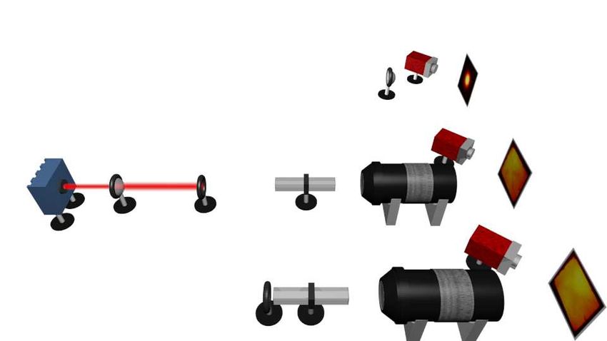
In this configuration, we have modified our experimental setup as it is illustrated on the Fig 3. We
have used a red (635nm) visible laser made by BBright (BB-635FC) and based on array semiconductor
laser technology. At the output, the beam is injected inside 1mm core diameter multimode optical fiber
with two meter length. At the fiber output, the configuration is close to the configuration 3 presented
on the Fig 1A where we can find a diffuser, a light pipe and a projector zoom. The output of the light
pipe is projected on a typical projection screen without perforation at a distance of about four meters
from the zoom. We can change the image size or the laser power in order to obtain a luminance of about
12cd/m2 . This value is measured by a standard control device (QALIF) used in the cinema industry and
fabricated by Highlands Technologies Solutions. In order to study how to decrease the subjective speckle,
we have modified the configuration at different aspects that we will describe in the following.
First, we have measured contrast in a configuration where the diffuser is removed and only the fiber
and the light pipe are used. We can see on the Fig. 4 in the blue bar that the contrast is about 12.6%.
However, in this context, the multimode fiber plays already a role to reduce the speckle because of theFigure 3: Experimental setup. Diff: diffuser, LP: light pipe, Zoom: cinema projector zoom
presence of numerous transversal mode in the fiber (core diameter of one milimeter) [1, 16]. We haven’t
quantify this quantity because the final result is higher than ten percent.
Afterwards, we have added either 120 grit or 600 grit diffuser representated on the Fig. 4. The
difference between the green and the yellow bar is the area under which the diffuser is illuminated. In
green, we have a small area of illumination because we have placed the fiber very close to the diffuser. In
this case, only a small quantity of granularities is illuminated. We obtain a contrast value respectively
of about 10.6% and 11.5% for 120grit and 600grit. This decrease is small because the phase variation
introduce by the diffuser on the incident field is not enough to remove an important part of the speckle.
Now, if we increase the illumination area by a factor four, we obtain a contrast value respectively of
about 9.35% and 9.75% for the 120grit and 600grit. Furthermore, for each barplot, we have calculated
the errorbar from the Eq 3. So, first, all the values are out of the incertainty. Then, the incident surface
illumination of the diffuser play an important role to reduce the subjective speckle. But the counter part
of this operation is important losses of the optical power which has to be compensate by increasing the
power of the source if we want to maintain the same screen size.
Figure 4: Impact of the incident area illumination on the speckle. We have calculated the contrast
in a configuration with the light pipe and with or without diffusers. In the last case, we have watched
the impact of the incident area illumination of the diffuser on the speckle.
Impact of the magnification on the subjective speckle
The last key ingredient in a cinematographic projection system is the simple linear propagation of light
towards the screen. In real systems, the output facet of the light pipe is imaged onto the device used
to spatially modulate the beam intensity in agreement to the digital content to be displayed. Then,
the image of this spatial modulator (nowadays more and more frequently a Digital Light Processor) is
projected onto the screen with minimal distortion but a very large magnification. Typically, the Digital
Light Processor size is of the order of a couple of centimeters, while the screen diagonal is more than
ten meters, which implies at least 102 magnification. For the purpose of subjective speckle measurement,the Digital Light Processor is not useful since aim at measuring deviations from a perfectly flat intensity
profile. Therefore, we bypass it and project directly onto the screen the image of the exit facet of the
light pipe. On figure 5, we show the measured contrast value for different magnifications, obtained by
increasing the propagation distance between the objective and the screen, for two different diffusors.
Both curves are shifted with respect to each other due to the different diffusors as expected. Much more
importantly the speckle contrast increases with the screen width, ie with the magnification after the
beam exits the projection system.
Figure 5: Influence of the objectif magnification on the subjective speckle. We have changed
the objectif magnification and studied the corresponding contrast for two different diffuser grit. In thick
blue line and thick green line, we have respectively the diffuser with 120grit and 600grit. In dashed line,
the contrast is calculated from one first part of the image and in points-dashed line for an another part.
In black black line, the theoritical error is calculated.
Acknowledgments
We acknowledge financial support of Région Provence Alpes Côte d’Azur and Bpifrance Financement
through contract number DS0025574/00.
References
[1] J. W. Goodman, Speckle phenomena in optics: theory and applications (Roberts and Company
Publishers, 2007).
[2] J. W. Goodman, Statistical optics (John Wiley & Sons, 2015).
[3] N. George and A. Jain, “Speckle reduction using multiple tones of illumination,” Appl. Opt. 12,
1202–1212 (1973).
[4] S. Lowenthal and D. Joyeux, “Speckle removal by a slowly moving diffuser associated with a mo-
tionless diffuser,” J. Opt. Soc. Am. 61, 847–851 (1971).
[5] S. Kubota and J. W. Goodman, “Very efficient speckle contrast reduction realized by moving diffuser
device,” Appl. Opt. 49, 4385–4391 (2010).
[6] P.-H. Yao, C.-H. Chen, and C.-H. Chen, “Low speckle laser illuminated projection system with a
vibrating diffractive beam shaper,” Opt. Express 20, 16552–16566 (2012).
[7] J.-W. Pan and C.-H. Shih, “Speckle reduction and maintaining contrast in a laser pico-projector
using a vibrating symmetric diffuser,” Opt. Express 22, 6464–6477 (2014).
[8] Y. Zhang, H. Dong, R. Wang, J. Duan, A. Shi, Q. Fang, and Y. Liu, “Demonstration of a home
projector based on rgb semiconductor lasers,” Appl. Opt. 51, 3584–3589 (2012).[9] E. G. Rawson, A. B. Nafarrate, R. E. Norton, and J. W. Goodman, “Speckle-free rear-projection
screen using two close screens in slow relative motion,” J. Opt. Soc. Am. 66, 1290–1294 (1976).
[10] V. Yurlov, A. Lapchuk, S. Yun, J. Song, and H. Yang, “Speckle suppression in scanning laser display,”
Appl. Opt. 47, 179–187 (2008).
[11] M. N. Akram, Z. Tong, G. Ouyang, X. Chen, and V. Kartashov, “Laser speckle reduction due to
spatial and angular diversity introduced by fast scanning micromirror,” Appl. Opt. 49, 3297–3304
(2010).
[12] L. Wang, T. Tschudi, T. Halldórsson, and P. R. Pétursson, “Speckle reduction in laser projection
systems by diffractive optical elements,” Appl. Opt. 37, 1770–1775 (1998).
[13] G. Ouyang, Z. Tong, M. N. Akram, K. Wang, V. Kartashov, X. Yan, and X. Chen, “Speckle reduction
using a motionless diffractive optical element,” Opt. Lett. 35, 2852–2854 (2010).
[14] M. Sun and Z. Lu, “Speckle suppression with a rotating light pipe,” Opt. Eng. 49, 024202 (2010).
[15] A. L. Petoukhova, E. Cleven, F. F. M. de Mul, and W. Steenbergen, “Suppression of dynamic laser
speckle signals in multimode fibers of various lengths,” Appl. Opt. 43, 2059–2065 (2004).
[16] D. S. Mehta, D. N. Naik, R. K. Singh, and M. Takeda, “Laser speckle reduction by multimode
optical fiber bundle with combined temporal, spatial, and angular diversity,” Appl. Opt. 51, 1894–
1904 (2012).
[17] S. Roelandt, J. Tervo, Y. Meuret, G. Verschaffelt, and H. Thienpont, “Propagation of partially
coherent light through a light pipe,” Opt. Express 21, 17007–17019 (2013).
[18] S. Zhang, “A simple bi-convex refractive laser beam shaper,” Journal of Optics A: Pure and Applied
Optics 9, 945 (2007).
[19] P.-C. Chen, C.-C. Chen, P.-H. Yao, and C.-H. Chen, “Double side lenslet array for illumination
optics of laser projector,” in “Emerging Liquid Crystal Technologies IV,” , vol. 7232 (International
Society for Optics and Photonics, 2009), vol. 7232, p. 72320X.You can also read