SuperBrush 49 OWNERS'S MANUAL - Laguna Tools
←
→
Page content transcription
If your browser does not render page correctly, please read the page content below
OWNERS’S MANUAL

SuperBrush 49

    Lagunatools.com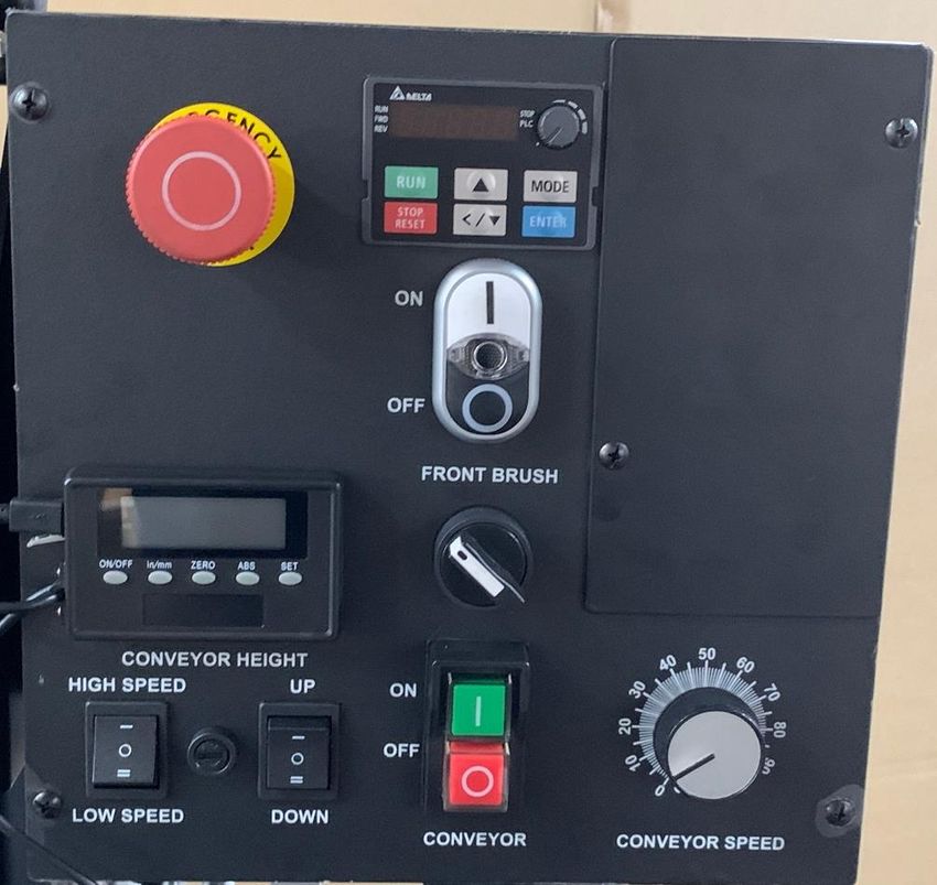
Thank you for investing in a SuperMax SuperBrush by Laguna Tools.
This brush sander is one of a family of unique machines proudly
offered by Laguna Tools. Every Laguna machine is engineered for
years of dependable service. Please feel free to contact Laguna Tools
if you have a question or suggestion. We appreciate working with you
and your choice of a Laguna Tools machine for your shop.

Regards,
Torben Helshoj
President & Founder Laguna Tools

                         Dealer Machinery Warranty
New woodworking machines sold by Laguna Tools carry a two-year warranty effective
from the date of dealer invoice to consumer. Machines sold through dealers must be
registered with Laguna Tools within 30 days of purchase to be covered by this warranty.
Laguna Tools guarantees all new machine sold to be free of manufacturers’ defective
workmanship, parts and materials. We will repair or replace, without charge, any parts
determined by Laguna Tools, Inc. to be a manufacturer’s defect. We require that the
defective item/part be returned to Laguna Tools with the complaint. An RMA (return
merchandise authorization) must be requested, from Laguna Tools, and included with
any and all parts or machines returned to Laguna Tools for warranty consideration. Any
machines returned to Laguna Tools must be returned with packaging in the same
manner in which it was received. If a part or blade is being returned it must have
adequate packaging to ensure no damage is received during shipping. In the event the
item/part is determined to be damaged due to lack of maintenance, cleaning or
misuse/abuse, the customer will be responsible for the cost to replace the item/part, plus
all related shipping charges. This limited warranty does not apply to natural disasters,
acts of terrorism, normal wear and tear, product failure due to lack of maintenance or
cleaning, damage caused by accident, neglect, lack of or inadequate dust collection,
misuse/abuse or damage caused where repair or alterations have been made or
attempted by others.

This manual applies to the SuperBrush 49. Enter the model number and
serial number below for quick reference when ordering accessories, supplies
or parts. NOTE: The model and serial number plate can be found on the
cross rail, below the conveyor, when viewed from the infeed/front of the
machine.

Model: ___________

Serial: ___________

Laguna Tools                                                   7291 Heil Avenue
Huntington Beach                                               CA 92647

                 800-234-1976                       www.lagunatools.com

                                  LAGUNATOOLS.COM                                        2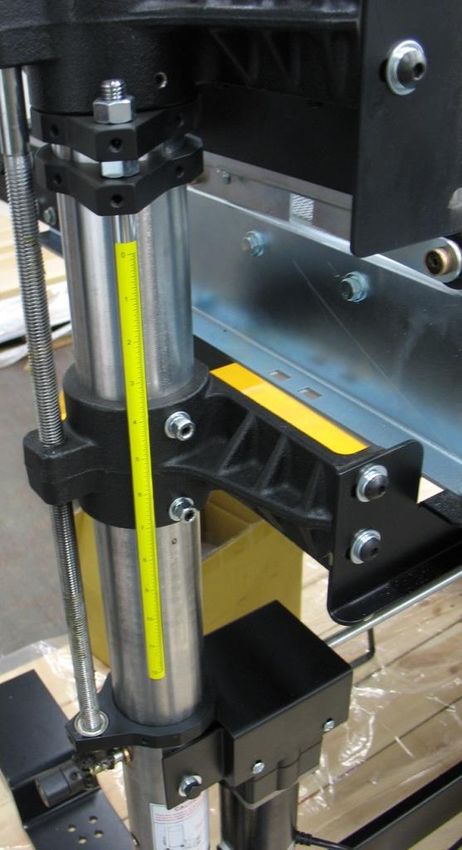
CONTENTS
Warranty:                             02

Safety:                               04
     Important Safety Instructions    05
     General Safety Rules             09

Unpacking:                            12

Assembly:                             13

Components:                           19

Power Supply:                         20
    Connecting Power                  20
    Wiring Diagrams                   23

Operation:                            25

Maintenance:                          29

Trouble Shooting:                     29

Exploded Views:                       30
     Parts List                       31

Specifications:                       40

Supplies:                             40

                    LAGUNATOOLS.COM        3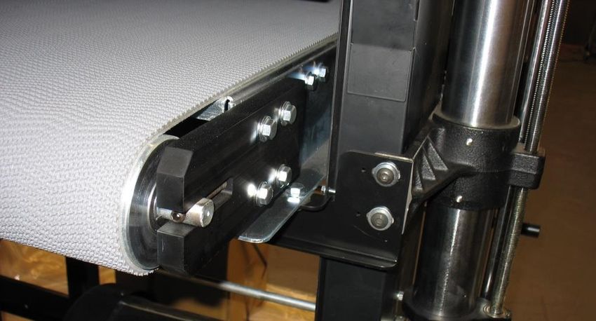
SAFETY
READ AND UNDERSTAND THIS MANUAL AND ALL INSTRUCTIONS BEFORE USING THIS
EQUIPMENT. Failure to follow all instructions may result in electric shock, fire and/or
serious personal injury or property damage! Electronic copies of this manual are
available at www.lagunatools.com.

SAFETY GUIDELINES - DEFINITIONS
This manual contains information that is important for you to know and
understand. This information relates to protecting YOUR SAFETY and
PREVENTING EQUIPMENT PROBLEMS. To help you recognize this information,
we use the symbols below. Please read the manual and pay attention to
these sections.

Indicates an imminently hazardous situation which, if not avoided, will result in death or
serious injury.

Indicates a potentially hazardous situation which, if not avoided, could result in death or
                                      serious injury.

Indicates a potentially hazardous situation which, if not avoided, may result in minor or
moderate
injury.

(Used without the safety alert symbol) indicates a potentially hazardous situation which,
if not avoided, may result in property damage.

                                  LAGUNATOOLS.COM                                           4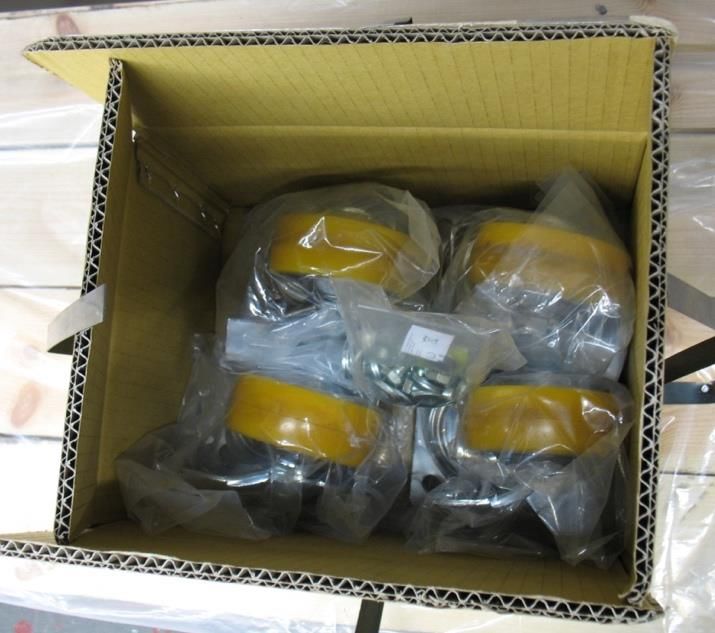
Woodworking, metalworking, composites, etc. (and similar materials) can be dangerous
if safe and proper operating procedures are not followed. As with all machinery, there
are certain hazards involved with the operation of the machine. Using the machine with
respect and caution will considerably lessen the possibility of personal injury. However,
if normal safety precautions are overlooked or ignored, personal injury to the operator
may result. Safety equipment such as guards, push sticks, hold-downs, featherboards,
goggles, dust masks and hearing protection can reduce the potential for injury. Even
the best guard will not make up for poor judgement, carelessness or inattention.
Always use common sense and exercise caution in the workshop. If a procedure feels
dangerous, do not try it. Figure out an alternative procedure that is safer. REMEMBER:
Your personal safety is your responsibility.

IMPORTANT SAFETY INSTRUCTIONS

This machine was designed for certain applications only. We strongly
recommend that this machine not be modified and/or used for any
application other than that for which it was designed. If you have any
questions relative to a particular application, DO NOT use the machine until
you have first contacted the manufacturer to determine if it can or should be
performed on the product.

If you have any questions relative to its application DO NOT use the product
until you have contacted the manufacturer and we have advised you.

When using an electrical appliance/machine, basic precautions should always
be followed, including the following:

          READ ALL INSTRUCTIONS BEFORE USING (THIS MACHINE)!

To reduce the risk of fire, electric shock, or injury:
1. Do not leave appliance when plugged in. Unplug from outlet when not in
use and before servicing.
2. Do not use outdoors or on wet surfaces
3. Do not allow to be used as a toy. Close attention is necessary when used
by or near children.
4. Use only as described in this manual. Use only manufacturer’s
recommended attachments.
5. Do not use with damaged cord or plug. If appliance is not working as it
should, has been dropped, damaged, left outdoors, or dropped into water,
return it to a service center.

                                  LAGUNATOOLS.COM                                       5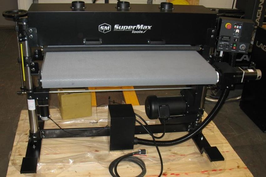
6. Do not pull or carry by cord, use cord as a handle, close a door on cord, or
pull cord around sharp edges or corners. Do not run appliance over cord.
Keep cord away from heated surfaces.
7. Do not unplug by pulling on cord. To unplug, grasp the plug, not the cord.
8. Do not handle plug or appliance with wet hands.
9. Do not put any object into openings. Do not use with any opening blocked;
keep free of dust, lint, hair, and anything that may reduce air flow.
10. Keep hair, loose clothing, fingers, and all parts of body away from
openings and moving parts.
11. Turn off all controls before unplugging.
12. Use extra care when cleaning on stairs.
13. Do not use to pick up flammable or combustible liquids, such as gasoline,
or use in areas where they may be present.
14. Connect to a properly grounded outlet only. See Grounding Instructions.

SAVE THESE INSTRUCTIONS

   1. Read and understand the warnings posted on the machine and
      in this manual. Failure to comply with all of these warnings
      may cause serious injury.

   2. Replace the warning labels if they become obscured or removed.

   3. This SuperBrush is designed and intended for use by properly trained
      and experienced personnel only. If you are not familiar with the proper
      and safe operation of this type of machine, do not use until proper
      training and knowledge have been obtained.

   4. Do not use this machine for other than its intended use. If used for
      other purposes, LAGUNA TOOLS INC., disclaims any real or implied
      warranty and holds itself harmless from any injury that may result
      from that use.

   5. Always wear approved safety glasses/face shields while using this
      machine.

   6. Before operating this machine, remove tie, rings, watches and other
      jewelry, and roll sleeves up past the elbows. Remove all loose clothing
      and confine long hair. Non-slip footwear or anti-skid floor strips are
      recommended.

   7. Wear ear protectors (plugs or muffs) during extended periods of
      operation.

   8. Some dust created by power sanding, sawing, grinding, drilling and
      other construction activities contain chemicals known to cause cancer,
      birth defects or other reproductive harm. Some examples of these
      chemicals are: (next page)

                              LAGUNATOOLS.COM                                  6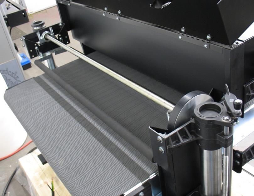
•     Lead from lead based paint.
   •     Crystalline silica from bricks, cement and other masonry
         products.
   •     Arsenic and chromium from chemically treated lumber.

   Your risk of exposure varies, depending on how often you do this type
   of work. To reduce your exposure to these chemicals, work in a well-
   ventilated area and work with approved safety equipment, such as
   face or dust masks/respirators that are specifically designed to filter
   out microscopic particles.

9. Do not operate this machine while tired or under the influence of
   drugs, alcohol or any medication.

10.Make certain the switch is in the OFF position before connecting the
   machine to the power source.

11.Make certain the machine is properly grounded.

12.Make all machine adjustments or maintenance with the machine
   unplugged from the power source.

13.Form a habit of checking to see that all extra equipment such as
   adjusting keys, wrenches, scrap, stock, and cleaning rags are removed
   away from the machine before turning on.

14.Keep safety guards in place at all times when the machine is in use. If
   removed for maintenance purposes, use extreme caution and replace
   the guards immediately when maintenance is complete.

15.Make sure the dust collector is on a flat even surface and the wheels
   locked in place before use.

16.Check damaged parts. Before further use of the machine, a guard or
   other part that is damaged should be carefully checked to determine
   that it will operate properly and perform its intended function. Check
   for alignment of moving parts, binding of moving parts, breakage of
   parts, mounting and any other conditions that may affect its operation.
   A guard or other part that is damaged should be properly repaired or
   replaced.

17.Provide for adequate space surrounding work area and non-glare,
   overhead lighting.

18.Keep the floor around the machine clean and free of scrap material, oil
   and grease.

                          LAGUNATOOLS.COM                                    7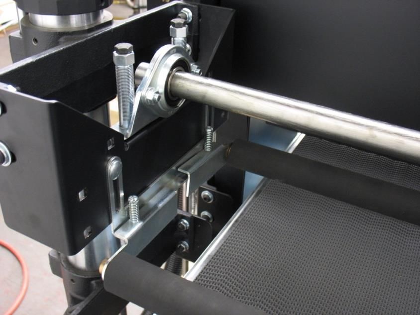
19.Keep visitors a safe distance from the work area. Keep children
      away.

   20.Make your workshop child proof with padlocks, master switches or by
      removing starter keys.

   21.Give your work undivided attention. Looking around, carrying on a
      conversation and “horse-play” are careless acts that can result in
      serious injury.
      .
   22.Maintain a balanced stance at all times so that you do not fall or lean
      against the dust collector. Do not overreach or use excessive force to
      perform any machine operation.

   23.Use the right tool at the correct speed and feed rate. Do not force a
      tool or attachment to do a job for which it was not designed. The right
      tool will do the job better and safer.

   24.Use recommended accessories; improper accessories may be
      hazardous.

   25.Maintain machinery with care. Follow instructions for lubricating and
      changing accessories.

   26.Turn off the machine before cleaning. Use a brush or compressed air
      to remove dust or debris — do not use your hands.

   27.Do not stand on the machine. Serious injury could occur if the machine
      tips over.

   28.Never leave the machine running unattended. Turn the power off and
      do not leave the machine until it comes to a complete stop.

   29.Never operate or run the machine without closing the drum up against
      the lid. Failure to do so will result in the machine amperage increasing
      and may trip your circuit.

Familiarize yourself with the following safety notices used in this manual:

SAFETY GUIDELINES - DEFINITIONS
This manual contains information that is important for you to know and
understand. This information relates to protecting YOUR SAFETY and
PREVENTING EQUIPMENT PROBLEMS. To help you recognize this information,
we use the symbols, described earlier. Please read the manual and pay
attention to these sections.

                              LAGUNATOOLS.COM                                   8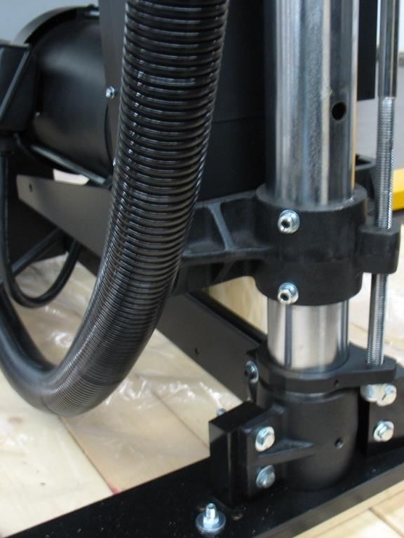
GENERAL SAFETY RULES

FAILURE TO FOLLOW THESE RULES MAY RESULT IN SERIOUS
INJURY.

FOR YOUR OWN SAFETY, READ AND UNDERSTAND THE INSTRUCTION
MANUAL BEFORE OPERATING THE MACHINE. Learn the unit’s application
and limitations as well as the specific hazards peculiar to it.

KEEP WORK AREA CLEAN. Cluttered areas and benches invite accidents.

DON’T USE IN DANGEROUS ENVIRONMENT. Don’t use this unit in damp
or wet locations, or expose it to rain. Keep work area well-lighted.

KEEP CHILDREN AND VISITORS AWAY. All children and visitors should be
kept a safe distance from work area.

DISCONNECT UNIT before servicing.

CHECK DAMAGED PARTS. Before further use of the unit, properly repair or
replace any part that is damaged.

FAILURE TO FOLLOW THESE RULES MAY RESULT IN SERIOUS
INJURY.

ADDITIONAL SAFETY INFORMATION
Intended use. This machine is intended for the applications discussed and
approved by Laguna/SuperMax. Do not use this machine for non-approved
applications or flammable, combustible, or hazardous materials.

Hazardous dust. Dust created while using machinery may cause cancer,
birth defects, or
long-term respiratory damage. Be aware of dust hazards associated with
each work piece material, and always wear a NIOSH-approved respirator to
reduce your risk.

Dust allergies. Dust from certain woods and other materials may cause an
allergic reaction in people and animals. Make sure you know what type of
dust you will be exposed to in case there is a possibility of an allergic
reaction.

                            LAGUNATOOLS.COM                                 9
Wear respirator. Fine dust that is too small to be caught in the filter may
be introduced into the ambient air during operation. Always wear a NIOSH-
approved respirator during operation and for a short time after to reduce
your risk of permanent respiratory damage.

Disconnecting power supply. Turn the switch off, disconnect from the
power supply, and allow machine to come to a complete stop before leaving
the machine unattended or doing any service, cleaning, maintenance, or
adjustments.

Suspended dust particles and ignition sources. Do not operate in areas
were explosion risks are high. Areas of high risk include, but are not limited
to, areas near pilot lights, open flames, or other ignition sources.

Fire suppression. Only operate in locations that contain a fire suppression
system or have a fire extinguisher nearby.

Static electricity. Plastic dust lines generate high amounts of static
electricity as dust chips pass through them. Although rare, sparks caused by
static electricity can cause explosions or fire. To reduce this risk, make sure
all dust lines are thoroughly grounded by using a grounding wire.

Regular cleaning. Regularly check the machine for excessive dust and
debris and clean. Make sure to regularly clean the surrounding area where
the machine is operated—excessive dust buildup on overhead lights, heaters,
electrical panels, or other heat sources will increase the risk of fire.

             SAVE THESE INSTRUCTIONS.
 Refer to them often and use them to instruct others.
Please read and save these instructions. Read carefully before attempting to
assemble, install, operate or maintain the product described. Protect yourself
and others by observing all safety information. Failure to comply with
instructions could result in personal injury and/or property damage! Retain
instructions for future reference.

DO NOT EXPOSE THE MACHINE TO RAIN OR OPERATE THE MACHINE IN
DAMP LOCATIONS.

                              LAGUNATOOLS.COM                                 10
MOTOR SPECIFICATIONS
The typical main motor is 10 HP and is wired for 208-230 Volt, Three-Phase,
60 HZ, AC current. Confirm your motor electrical configuration before
connecting power! Before connecting the machine to the power source, make
sure the starter and switches are in the "OFF" position. Power Cord and
“plug” are NOT included. These must be installed by a qualified
technician/electrician to meet all applicable codes.
Confirm electrical configuration (Voltage & Phase) of brush machine before
connecting to power source!
GROUNDING INSTRUCTIONS
THIS MACHINE MUST BE GROUNDED WHILE IN USE TO PROTECT THE
OPERATOR FROM ELECTRIC SHOCK.
1. This machine must be connected to a grounded metal, permanent wiring
system; or an equipment-grounding conductor must be run with the circuit
conductors and connected to the equipment-grounding terminal or lead on
the appliance.
The installer, such as a qualified electrician, shall cut (or bend over) and
insulate the grounding conductor from a field wiring supply cable.
In the event of certain types of malfunctions or breakdowns, grounding
provides a path of least resistance for electric current—in order to reduce the
risk of electric shock.
Improper connection of the equipment-grounding wire can result in a risk of
electric shock. The wire with green insulation (with or without yellow stripes)
is the equipment-grounding wire. If repair or replacement of the power cord
or plug is necessary, do not connect the equipment-grounding wire to a live
(current carrying) terminal.
Check with a qualified electrician or service personnel if you do not understand
these grounding requirements, or if you are in doubt about whether the tool is
properly grounded. If you ever notice that a cord or plug is damaged or worn,
disconnect it from power, and immediately replace it with a new one.
Full Load Amperage Draw; 208V 3 Phase ...........................29 Amps
LAGUNATOOLS.COM 11Power Supply Circuit Requirements
The power source circuit for your machine must be g r o u n d e d and
r a t e d f o r the a m p e r a g e given below. Never replace a circuit breaker
on an existing circuit with one of higher amperage without consulting a
qualified electrician to ensure compliance with wiring codes. If you are
unsure about the wiring codes in your area or you plan to connect
your machine to a shared circuit, consult a qualified electrician.
Circuit Size (208-230V, 3-Phase) ................30 Amp. minimum
IN ALL CASES, MAKE CERTAIN THE RECEPTACLE OR DISCONNECT IS
PROPERLY GROUNDED. IF YOU ARE NOT SURE, HAVE A QUALIFIED
ELECTRICIAN CHECK THE RECEPTACLE OR DISCONNECT.
UNPACKING
Your SuperBrush 49 comes packed in a single box attached to a pallet.
Before attempting to assemble this machine, follow these directions:
1. Carefully cut the banding straps and remove them from the box.
2. Remove the box covering the machine.
3. Remove the plastic cover from the machine.
4. Remove the small box from the pallet.
5. Remove the four bolts securing the machine to the pallet.
6. Using the picture below, ensure that all parts are present and in good
condition.
Figure 1: Inventory NOTE: Electrical cord and plug are not
included.
LAGUNATOOLS.COM 12DESCRIPTION (QUANTITY)
A. Box (4 Casters & hardware)
B. Owner’s Manual (1)
C. CR-2032 Batteries (2)
Figure 2: Casters & Hardware
Report any missing or damaged parts to your dealer or distributor. Prior to
machine assembly and use, read this manual thoroughly to familiarize
yourself with proper assembly, maintenance and safety procedures.
ASSEMBLY
This step requires a forklift. The SuperBrush 49 is heavy, be careful when
lifting and handling it with a forklift! Failure to comply may cause serious
injury and/or damage to the machine and/or property!
Tools/items Required:
9/16” wrench
1/2” wrench
5mm hex wrench
Power Cord and Plug (unless hard wiring into a disconnect)
LAGUNATOOLS.COM 13To assemble your SuperBrush 49, follow these steps:
For your own safety, do not connect the machine to the power source until
the machine is completely assembled. Please also make sure that you read
and understand the entire manual.
1. Make sure the four locking set screws in the Table Support Casting are
tight. Unbolt machine from pallet. Using a forklift, lift the SuperBrush 49
from the pallet. The forks should lift from under the conveyor support cross
members. Be careful when placing the forks not to damage other areas or
wiring, Fig. 3 & 5.
Figure 3: Table Support Set Screws
2. Attach the four casters to the legs of the machine by using the included
bolts and washers through each hole of the caster (from the bottom-up) into
the leg of the machine, Fig. 4. Start all four bolts and washers before
tightening the bolts.
LAGUNATOOLS.COM 14Figure 4: Attaching casters
3. Lower the machine to the floor.
Table Support Set
Screws (2 each side)
Figure 5: Table Support Set Screws
LAGUNATOOLS.COM 154. Loosen the four nuts then the four set screws locking the table support
casting, Fig. 5. Finger tighten these same set screws. Hold the set screw
with a Hex wrench and tighten the nut. Note, these set screws are brass
tipped and are designed to lightly rub on the column.
5. Loosen the two set screws in the motor support casting, Fig. 6. Important:
Loosen these set screws before attempting to raise or lower motor for brush
installation!
Motor Support
Set Screws (2)
Figure 6: Motor Lock Set Screws
6. Check tightness of all hardware.
NOTE: shipping can loosen nuts, bolts and set screws.
7. Remove shipping shaft from brush machine, Fig. 7;
A. Loosen drive belt by raising motor with motor tension handle on top of
the column near drive belt.
B. Slide drive belt off pulley.
C. Remove two bolts from each bearing.
D. Remove shipping shaft from brush sander.
E. Loosen set screws in each bearing and driven pulley.
F. Slide pulley and bearings off shaft.
LAGUNATOOLS.COM 16Hand Crank, motor
Bearings (2)
Shipping Arbor
Mounting Bolts (2)
Set Screws (2)
Pulley
Figure 7A & B: Shipping Arbor and Bearings
8. Installing brush head;
A. Install brush head (if not already installed) by removing brush head
from shipping box.
B. Slide one bearing (from Shipping Arbor) on each end of the brush
shaft. Do not yet tighten the set screws for the bearing collar, Fig. 7B.
C. Place the shaft key into the key slot of the drive shaft of the brush head.
D. Slide the pulley, Fig. 7A (from Shipping Arbor) onto the drive shaft over
the key.
E. Raise the main motor by using the hand crank, Fig. 7A, at the top of the
column to lift the motor.
F. Place the brush head into the brush machine while holding the drive
belt out-of-the-way.
G. Center the brush head over the conveyor and install Mounting Bolts,
Fig. 7B, from the flange of the bearing into the mating bracket of the
brush machine. Tighten the bearing mounting bolts.
H. Tighten the two set screws, Fig. 7B, in each bearing collar to secure the
brush head shaft to the bearings.
I. Align the pulley of the brush head with the drive pulley of the main
motor. Secure by tightening the set screw(s) in the driven pulley.
J. Lower the main motor for proper tension of the drive belt. Proper
tension is slight deflection of the drive belt when pressed from the side.
K. Make sure all bolts and set screws are tight.
LAGUNATOOLS.COM 179. Check alignment (parallelism) of the brush head to the conveyor. Measure
from the bottom of the brush bristles to the top of the conveyor belt on the right
and left side. If the brush head is not parallel;
A. loosen the two bearing bolts (that secure the bearing to the machine)
on the lower side of the brush, Fig. 8.
B. Raise the bearing on the low side by using a hex wrench in the center
of the bearing stud and rotate both equally until the brush head is
parallel.
C. Tighten the bolts attaching the bearing to the machine bracket.
Bearing Bolts
Bearing Stud
Figure 8: Aligning Brush Head
Dust Collection, Connection/Assembly
1. Connect dust collection hose to each 4” port on machine. Minimum of *600
CFM per port.
*NOTE: The CFM requirement can vary depending on brush head, application(s) and material.
Dust Ports (3)
Figure 9: Dust Ports
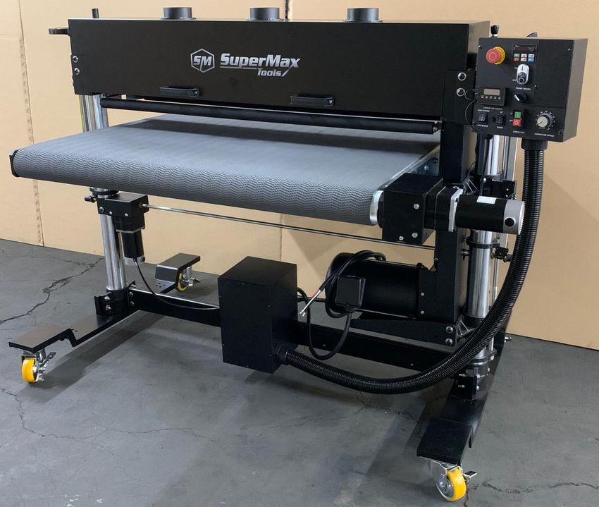
LAGUNATOOLS.COM 18COMPONENTS
Emergency Stop
Motor Raising
Handle (behind
Conveyor Height Control Panel)
(manual)
Control Panel
Tension Rollers
(See Fig. 12)
(2)
Conveyor
Conveyor Motor
Conveyor Lift
Motor
Main Motor
Figure 10: Main Components of SuperBrush 49
NOTE: Assembly is continued in next section “Power Supply”
LAGUNATOOLS.COM 19POWER SUPPLY
Power Supply Circuit Requirements
The power source circuit for your machine must be g r o u n d e d and
r a t e d f o r the a m p e r a g e given below. Never replace a circuit breaker
on an existing circuit with one of higher amperage without consulting a
qualified electrician to ensure compliance with wiring codes. If you are
unsure about the wiring codes in your area or you plan to connect
your machine to a shared circuit, consult a qualified electrician.
Circuit Size (208-230V, 3-Phase) .................30 Amp minimum
IN ALL CASES, MAKE CERTAIN THE RECEPTACLE IN QUESTION IS PROPERLY
GROUNDED. IF YOU ARE NOT SURE, HAVE A QUALIFIED ELECTRICIAN
CHECK THE RECEPTACLE.
MOTOR SPECIFICATIONS
The typical main motor is 10 HP and is typically wired for 208-230 Volt,
Three Phase, 60 HZ, AC current. Confirm your motor electrical configuration
before connecting power! Before connecting the machine to the power
source, make sure the starter and switches are in the "OFF" position. Cord
and “plug” are NOT included. These must be installed by a qualified
technician/electrician to local codes.
Figure 11: Electrical Connection Box
LAGUNATOOLS.COM 20NOTE: A “plug” and cord are NOT included and must be installed by a
qualified technician/electrician or the power cable connected (hard wired) to
an appropriate disconnect according to local codes.
A qualified electrician should do the connection. When completed, the
machine must conform to the National Electric Code and all local codes and
ordinances.
FUNCTION, Control Panel (Front)
RPM Adjustment
Emergency
STOP
RPM Readout
Brush ON/OFF
DRO
Brush Rotation
Conveyor
height speed
Conveyor Speed
Conveyor Fuse Conveyor Conveyor
UP/DOWN ON/OFF
Figure 12: Control Panel Components
LAGUNATOOLS.COM 21FUNCTION, Control Panel Back
Motor Height Adjustment
Conveyor High Speed
Adjustment
Figure 13: Control Panel Components (Back)
NOTE: The speed of “High Speed” Conveyor lifting can be adjusted on the back of
the
control panel with a rotating stud.
LAGUNATOOLS.COM 22WIRING DIAGRAMS
POWER CONNECTIONS
Figure 14: Power Connections & Wiring
LAGUNATOOLS.COM 23INTERNAL WIRING
Figure 15: Internal Wiring
LAGUNATOOLS.COM 24OPERATION
1. Confirm brush head is parallel to conveyor bed. See Page 17, “Checking
Parallelism” to adjust if necessary.
2. Confirm the electrical supply is correct and connected to machine.
3. Make sure no one is working on or doing maintenance to machine.
4. Adjust contact of brush head onto material to be processed by either
turning the height adjustment handle (1 revolution equals 1/32”), or by
pressing the UP/DOWN switch on the control panel. NOTE: brush contact will
vary with application(s), material and brush head configuration. Confirm
correct contact with sample testing information or your salesperson.
Manual
Height Adj.
Electronic
Height Adj.
Figure 16: Height Control Adjustments
Electronic Height
Adjustment
Figure 17: Height Control Adjustment, electronic
LAGUNATOOLS.COM 255. Confirm correct contact of hold-down (pressure) rollers. Adjust contact by
loosening the roller bracket in each corner and raising or lowering to provide
proper tension. Correct tension is achieved when material feeds through
brush properly without slipping on the conveyor belt.
Tension Roller Adj.
(2 each side)
Figure 18: Tension (Hold-Down) Roller Adjustment
6. DRO;
Install two CR-2032 batteries (included) by pulling the DRO from the Control
Box and removing the battery cover from the back and installing the
batteries.
DRO Calibration; the typical method to use the DRO is to read the
bristle penetration into stock being processed.
A. With machine “OFF”, place stock under the brush head.
B. Adjust conveyor table (up or down) until the tip of the longest
bristles are just about touching the material.
C. Press “ON” to turn the DRO on, Fig. 19.
D. Press “ZERO” to zero out the DRO, Fig. 19.
E. Press “in/mm” to select desired inch or millimeter setting, Fig. 19.
F. Remove material from under brush.
G. Raise conveyor to desired setting/bristle penetration. See sample
letter or confirm appropriate bristle penetration with salesperson.
NOTE: Appropriate bristle penetration will change with various
applications, materials and brush wear. Adjust accordingly.
Excessive bristle penetration will prematurely shorten brush life!
LAGUNATOOLS.COM 26Figure 19: DRO calibration
7. To start brush, press the “FRONT BRUSH” “ON” button on the front of the
Control Panel, (Fig. 19 & 39). Confirm brush rotation is correct for
application and material. If not correct, press OFF button, wait for machine
to stop. Change rotation with rotation switch with “Front Brush”. Turn ON
brush.
8. Staring Conveyor;
A. To start conveyor, press “CONVEYOR” “ON” button, Fig 20:
B. Adjust speed of conveyor with “CONVEYOR SPEED” dial, 0-100%.
E-STOP
Brush ON/OFF
Brush Rotation
Forward & Reverse
Conveyor Speed
Control
Conveyor ON/OFF
Figure 20: Brush & Conveyor controls
LAGUNATOOLS.COM 27NOTE: Conveyor belt will require (periodic) adjustment to maintain proper
tacking on conveyor bed. Adjust by tightening the adjustment stud, Fig. 21,
with a 5mm Hex Wrench) on the side the belt is drifting toward and loosen
the opposite side an equal rotation.
NOTE: Make adjustments before conveyor belt rubs on side of conveyor bed.
Tracking Stud
(2)
Figure 21: Conveyor Tracking
9. Adjust RPM of brush head by rotating knob on “VFD”, Fig. 12 (Variable
Frequency Display) adjustment panel on top of main control panel. Confirm
correct RPM with sample testing information or your salesperson. RPM reads
out on display.
Excessive RPM will prematurely shorten brush life!
10. Start dust collector (open blast gates if so equipped).
11. Place material on conveyor and maintain control of stock until the
tension roller is holding stock properly.
12. To stop, press the “OFF” buttons for the brush and conveyor, Fig. 20.
Press the “E-STOP” button if there is an Emergency, Fig. 20! To reset the E-
STOP button, twist and pull back on the button.
LAGUNATOOLS.COM 28The EMERGENCY STOP button should only be used for an Emergency! It
disconnects all power to the machine during an Emergency. It should not
be used as the normal shut down procedure and it should not be used
when conducting maintenance. Power should be positively disconnected
to the machine for maintenance or repairs.
MAINTENANCE
Conveyor Belt
Keep conveyor belt centered on conveyor bed. Adjust tracking stud as
needed.
Keep conveyor belt clean to help prevent slippage of material.
Dust Collection
To ensure proper operation and longest brush life of the SuperBrush it is
important to maintain full air flow of your dust collection system. Make sure
the filter media is clean and there are no obstructions in the ducting.
TROUBLESHOOTING
Symptom Possible Cause Possible Solution
Machine Power supply switched Ensure power supply is ON and
does not OFF or is faulty. has the correct voltage.
start or a
breaker Wall fuse/circuit breaker Ensure adequate circuit size;
trips. is blown/tripped. install inlet restrictor, replace
weak breaker.
Faulty power switch. Replace switch.
Motor is at fault. Test/repair/replace.
LAGUNATOOLS.COM 29Exploded Views
STAND ASSEMBLY
Figure 22: Stand Assembly
LAGUNATOOLS.COM 30Stand Assembly Parts List
Ref. Part
No. No. Description Size Qty.
1 ....... 31-0020 ................ HANDLE, SWIVEL ASSY ........................................ ............................... 1
2 ....... 20-0772 ................ ROLL PIN ................................................................ 3/16"X1" ................. 1
3 ....... 50-3080 ................ OILITE WASHER .................................................... 5/8” I.D. .................. 2
4 ....... 635DS-139 ........... E-RING .................................................................... E-10 ....................... 2
5 ....... 30-1112 ................ SUPPORT, ADJUSTING SCREW .......................... ............................... 2
6 ....... 10-2804 ................ SET SCREW ........................................................... 1/4”-20X1/2” ......... 18
7 ....... 30-1240 ................ SCREW, INBOARD HEIGHT ADJ. FOLLOW ......... ............................... 1
8 ....... 93497-2-108 ......... SPACER .................................................................. ............................... 2
9 ....... 20-1101-1 ............. GEAR, MITER HEAVY DUTY ................................. ............................... 6
10 ..... 50-3107 ................ OILITE ROUND BUSHING ...................................... 1/2” I.D. .................. 5
11 ..... 93497-2-111 ......... SUPPORT BLOCK .................................................. ............................... 4
12 ..... 20-1103 ................ SHAFT COLLAR ..................................................... 1/2” I.D. .................. 2
13 ..... 30-3044 ................ TUBE, COLUMN ..................................................... ............................... 1
14 ..... 30-1209B .............. SCREW, RPM, MOTOR .......................................... ............................... 1
15 ..... 30-5103 ................ MOUNT, MOTOR .................................................... ............................... 1
16 ..... 12-0003 ................ HEX NUT ................................................................. 5/16”-18 ................. 6
17 ..... 11-0206 ................ FLAT WASHER ....................................................... 5/16”X18X2t........... 6
18 ..... 10-9906 ................ SET SCREW, BRASS TIPPED ............................... 5/16”-18X3/4”......... 6
19 ..... 93497-2-119 ......... HEX CAP SCREW .................................................. 3/8”-16x2-1/4” ........ 8
20 ..... 11-9103 ................ FLAT WASHER ....................................................... 3/8”X23X2t........... 48
21 ..... 913002-121 .......... SOCKET HEAD BUTTON SCREW......................... 3/8”-16X1-1/4” ..... 12
22 ..... 80-2324 ................ NYLON WASHER ................................................... ............................... 1
23 ..... 93497-2-123 ......... CASTER .................................................................. 4PUKB ................... 4
24 ..... 30-1241 ................ SCREW, OUTBOARD HEIGHT ADJ. MAIN ........... ............................... 1
25 ..... 12-0209 ................ FLANGE LOCK NUT ............................................... 3/8”-16 ................. 25
26 ..... 30-1101-1 ............. BASE, COLUMN ..................................................... ............................... 2
27 ..... 93497-2-127 ......... BASE SUPPORT BRACKET................................... ............................... 1
28 ..... 12-8015 ................ NYLON INSERT LOCK NUT ................................... 5/8”-11 ................... 1
29 ..... 10-8905 ................ SET SCREW ........................................................... 1/2”-13X1/2” ........... 2
30 ..... 93497-2-130 ......... ROD, TRANSFER ................................................... ............................... 1
31 ..... 30-5206 ................ SUPPORT BRUSH .................................................. ............................... 2
32 ..... 20-1180-02 ........... SPACER .................................................................. ............................... 1
33 ..... 30-5204 ................ SUPPORT, OUTBOARD TABLE ............................ ............................... 1
34 ..... 93497-2-134 ......... BASE ....................................................................... ............................... 2
35 ..... 93267-2-135 ......... WASHER, OILITE ................................................... ............................... 2
36 ..... 93497-2-136 ......... HEX CAP SCREW .................................................. 3/8”-16X5/8” ......... 16
37 ..... 91267-146 ............ FLAT WASHER ....................................................... 5/8”X30X3t............. 1
38 ..... 80-4015 ................ CAP, PLASTIC COLUMN TUBE ............................. ............................... 2
39 ..... 10-2903 ................ SET SCREW ........................................................... 5/16”-18X3/8”......... 8
40 ..... 40-0106 ................ MOTOR MOUNT ..................................................... ............................... 1
41 ..... 30-5205 ................ SUPPORT, INBOARD TABLE ................................ ............................... 1
42 ..... 40-0049 ................ BRACKET, TABLE MOUNT .................................... ............................... 2
43 ..... 93497-143 ............ COVER .................................................................... ............................... 1
44 ..... 31-0027 ................ HANDLE, SWIVEL, LARGE .................................... ............................... 1
45 ..... 30-1112-0 ............. SUPPORT, ADJUSTING SCREW, W/BEARING .... ............................... 4
46 ..... 93497-2-146 ......... SOCKET HEAD BUTTON SCREW......................... 3/8”-16X1” ............ 12
47 ..... 93267-2-147 ......... SET SCREW, BRASS TIPPED ............................... 1/4”-20X1” .............. 1
48 ..... 480BS-145............ FLAT WASHER ....................................................... 1/4”X16X2t............. 2
49 ..... 12-0001 ................ HEX NUT ................................................................. 1/4”-20 ................... 2
50 ..... 480BS-111............ LOCK WASHER ...................................................... 3/8” ...................... 33
51 ..... 93497-151 ............ SUPPORT BRACKET ............................................. ............................... 1
52 ..... 93497-152 ............ SCREW ................................................................... 1/4”-20X3/8” ........... 4
53 ..... 93497-153 ............ FLAT WASHER ....................................................... D27xd10x3t ........... 1
LAGUNATOOLS.COM 31Ref. Part
No. No. Description Size Qty.
54 ..... BB-R8ZZ ............... BEARING ................................................................. R8ZZ ...................... 4
55 ..... 93267-2-155 ......... SPACER .................................................................. ............................... 1
56 ..... 10-8802 ................ SET SCREW ........................................................... 5/16”-18X1/4”....... 14
57 ..... 93497-157 ............ DC GEAR MOTOR .................................................. 180VDC ................. 1
59 ..... 480BS-167............ LOCK WASHER ...................................................... 5/16” ...................... 6
60 ..... 635DS-343 ........... FLAT WASHER ....................................................... M6 .......................... 4
61 ..... 93267-2-413 ......... LOCK WASHER ...................................................... M6 .......................... 4
62 ..... 635DS-344 ........... HEX NUT ................................................................. M6X1.0 .................. 4
63 ..... 93267-2-409 ......... SOCKET HEAD CAP SCREW ................................ M6X1.0X80 ............ 4
64 ..... 91267-242 ............ HEX CAP SCREW .................................................. 3/8”-16X4” .............. 1
65 ..... 93497-165 ............ TUBE, COLUMN ..................................................... ............................... 1
66 ..... 93267-2-158 ......... SET SCREW ........................................................... 1/4”-20X1/4” ........... 4
LAGUNATOOLS.COM 32HEAD ASSEMBLY
Figure 23: Head Assembly (without brush)
LAGUNATOOLS.COM 33Head Assembly Parts List
Ref. Part
No. No. Description Size Qty.
1 ........40-3250 ................ DUST COVER ......................................................... ............................... 1
2 ........80-2841 ................ HANDLE, DUST COVER ........................................ ............................... 2
3 ........913002-121 .......... SOCKET HEAD BUTTON SCREW ........................ 3/8”-16X1-1/4” ....... 8
4 ........11-0104 ................ FLAT WASHER ....................................................... 3/8”X20X2t ............ 8
5 ........40-0613 ................ BRACKET, BEARING MOUNTING ......................... ............................... 1
6 ........50-3067 ................ BEARING ................................................................ ............................... 2
7 ........10-8802 ................ SET SCREW ........................................................... 1/4”-20X1/4” .......... 4
8 ........10-1203 ................ CARRIAGE BOLT ................................................... 5/16”-18X3/4” ........ 8
9 ........93497-2-209 ......... PULLEY ................................................................... ............................... 1
10 ......10-8903 ................ SET SCREW ........................................................... 5/16”-18X3/8” ........ 2
11 ......12-0209 ................ FLANGE LOCK NUT ............................................... 3/8”-16 ................... 8
12 ......91267-212 ............ SOCKET HEAD BUTTON SCREW ........................ 5/16”-18X3/8” ........ 4
13 ......10-3213 ................ SCREW ................................................................... 1/4”-20X1-3/4” ....... 4
14 ......40-0323 ................ BRACKET, LEFT SUSPENSION ............................ ............................... 2
15 ......20-3284 ................ SPRING, TENSION ROLLER ................................. ............................... 4
16 ......40-0326 ................ BRACKET, RIGHT SUSPENSION .......................... ............................... 2
17 ......50-3107 ................ OILITE ROUND BUSHING ..................................... 1/2” I.D. .................. 4
18 ......40-0322 ................ BRACKET, SUSPENSION BASE ........................... ............................... 2
19 ......480BS-111 ........... LOCK WASHER ...................................................... 3/8” ........................ 8
20 ......93497-2-220 ......... ROD ......................................................................... ............................... 1
21 ......30-5218 ................ ROLLER TENSION ................................................. ............................... 2
22 ......12-0207 ................ FLANGE LOCK NUT ............................................... 5/16”-18 ................. 4
23 ......40-0225 ................ HINGE ..................................................................... ............................... 3
24 ......40-4048 ................ BRACKET, DUST COVER MOUNTING ................. ............................... 1
25 ......10-3205 ................ SCREW ................................................................... 1/4”-20X1/2” ........ 12
26 ......11-0504 ................ INTERNAL TOOTH LOCK WASHER ..................... 1/4” ...................... 12
27 ......913022-203 .......... SCREW ................................................................... 5/16”-18X5/8” ........ 4
28 ......11-0205 ................ FLAT WASHER ....................................................... 1/4”X16X2t .......... 12
29 ......12-0001 ................ HEX NUT ................................................................. 1/4”-20 ................. 12
30 ......12-0003 ................ HEX NUT ................................................................. 5/16”-18 ................. 8
31 ......11-0505 ................ INTERNAL TOOTH LOCK WASHER ..................... 5/16” ...................... 4
33 ......40-0009 ................ GUARD, BELT COVER ........................................... ............................... 1
34 ......40-0010 ................ GUARD, BELT, PLATE ........................................... ............................... 1
35 ......91267-235 ............ GUARD, RIGHT BELT COVER .............................. ............................... 1
36 ......91267-236 ............ GUARD, LEFT BELT COVER ................................. ............................... 1
37 ......93267-2-237 ......... BEARING SET ........................................................ ............................... 1
38 ......10-3803 ................ SLOTTED HEX HEAD SCREW .............................. #10-24X3/8” ........... 6
39 ......635DS-207 ........... FLAT WASHER ....................................................... 5/16” ...................... 4
41 ......81-3132W ............. KNOB, LOCKING W/SET SCREW ......................... ............................... 2
42 ......30-1112 ................ SUPPORT, ADJUSTING SCREW .......................... ............................... 2
43A ....30-1260HR ........... DEPTH GAUGE ROD ............................................. ............................... 1
43B ....94-1654 ................ DECAL, SCALE ....................................................... ............................... 1
45 ......925002-109 .......... HEX NUT ................................................................. 1/2”-13 ................... 2
47 ......635DS-210 ........... DUST PORT ............................................................ ............................... 3
48 ......635DS-135 ........... SCREW ................................................................... 1/4”-20X3/8” ........ 12
50 ......91267-242 ............ HEX CAP SCREW .................................................. 3/8”-16X4” ............. 4
51 ......93267-2-251 ......... ADJUSTMENT NUT ................................................ ............................... 4
53 ......93497-2-253 ......... BRACKET, BEARING MOUNTING ......................... ............................... 1
54 ......93497-2-254 ......... BEARING SET ........................................................ ............................... 1
LAGUNATOOLS.COM 34CONVEYOR ASSEMBLY
Figure 24: Conveyor Assembly
LAGUNATOOLS.COM 35CONTROL PANEL ASSEMBLY (Incl. w/Conveyor Parts)
Figure 25: Control Panel Assembly (Included with Conveyor parts list)
LAGUNATOOLS.COM 36VFD & POWER IN ASSEMBLY (Incl. w/Conveyor Parts)
Figure 26: VFD & Power-In Assembly (included with Conveyor parts list)
LAGUNATOOLS.COM 37Conveyor Assembly Parts List, includes Control Box & VFD
Ref. Part
No. No. Description Size Qty.
1 ........635DS-361 ........... EMERGENCY STOP LABEL .................................. ............................... 1
2 ........93267-2-302 ......... EXTERNAL TOOTH LOCK WASHER .................... M4.......................... 2
3 ........93497-2-303 ......... CONTROL BOX SUPPORT BRACKET .................. ............................... 1
4 ........93497-2-304 ......... CONTACTOR .......................................................... ............................... 1
5 ........93267-2-305 ......... SOCKET HEAD BUTTON SCREW ........................ M5X0.8X8 .............. 5
6 ........93267-2-306 ......... HEX NUT ................................................................. M5X0.8 .................. 1
7 ........72-1260 ................ CONTROLLER, 180 VDC, VARIABLE SPEED, CONVEYOR ... ............................... 1
8 ........93497-308 ............ PLATE ..................................................................... ............................... 1
9 ........93497-2-309 ......... SCREW ................................................................... 5/16”-18X5/8” ........ 2
10 ......93267-2-310 ......... FUSE HOLDER ....................................................... ............................... 1
12 ......93497-2-312 ......... DC GEAR MOTOR .................................................. 180VDC ................. 1
13 ......93497-2-313 ......... STRAIN RELIEF ...................................................... PG-21 .................... 2
14 ......93497-2-314 ......... POLY-V BELT ......................................................... ............................... 1
15 ......93497-315 ............ LOWER CONTROL BOX ........................................ ............................... 1
16 ......93497-2-316 ......... KEY ......................................................................... 8x7x60 ................... 1
17 ......93267-2-317 ......... ZINC OXIDE VARISTOR ........................................ ............................... 1
18 ......72-6106-01A......... KNOB ...................................................................... ............................... 1
19 ......93497-2-319 ......... PULLEY, DRIVE ...................................................... ............................... 1
20 ......20-0763 ................ KEY ......................................................................... 3/16”X3/16”X3/4” ... 1
21 ......93267-2-321 ......... KEY ......................................................................... 3/16”x3/16”x1-1/4” . 1
22 ......40-1000 ................ LOWER, INNER BELT GUARD .............................. ............................... 1
23 ......93267-2-323 ......... FLAT WASHER ....................................................... 5/16”X18X2t .......... 2
24 ......12-0207 ................ FLANGE LOCK NUT ............................................... 5/16”-18 ................. 6
25 ......93497-2-325 ......... MOTOR, TEFC, 3 Phase ........................................ 10 HP ........................1
26 ......635DS-234 ........... CARRIAGE BOLT ................................................... 5/16”-18X1” ........... 4
27 ......10-9101 ................ HEX CAP SCREW .................................................. 5/16”-18X1/2” ........ 4
28 ......93497-2-328 ......... CONTROL HOUSING ............................................. ............................... 1
29 ......40-4116 ................ CONTROL BOX BOTTOM COVER ........................ ............................... 1
30 ......10-8902 ................ SET SCREW ........................................................... 5/16”-18X3/8” ........ 4
31 ......93497-2-331 ......... COUPLER ............................................................... ............................... 1
32 ......93497-2-332 ......... BRACKET, CONTROL HOUSING .......................... ............................... 1
33 ......93497-2-333 ......... RAIL, BED RH ......................................................... ............................... 1
34 ......93497-2-334 ......... RAIL, BED LH.......................................................... ............................... 1
35 ......12-0209 ................ FLANGE LOCK NUT ............................................... 3/8”-16 ................. 30
36 ......40-4153 ................ BRACKET, DRIVEN ROLLER SUPPORT .............. ............................... 2
37 ......40-4155A .............. BRACKET, DRIVE ROLLER SUPPORT LH ........... ............................... 1
38 ......40-4154 ................ BRACKET, DRIVE ROLLER SUPPORT RH .......... ............................... 1
39 ......13-1015 ................ BEARING, DRIVE ROLLER .................................... ............................... 2
40 ......30-3112-1 ............. ROLLER, DRIVE ..................................................... ............................... 1
41 ......30-3113 ................ ROLLER, DRIVEN................................................... ............................... 1
42 ......93267-2-375 ......... SCREW ................................................................... 1/4”-20X3/8” .......... 2
43 ......10-1302 ................ CARRIAGE BOLT ................................................... 3/8”-16X3/4” ........ 14
44 ......10-9207 ................ HEX CAP SCREW .................................................. 3/8”-16X1-1/2” ..... 12
45 ......10-9205 ................ HEX CAP SCREW .................................................. 3/8”-16X1” ............. 4
46 ......10-9215 ................ SET SCREW ........................................................... 3/8”-16X3” ............. 2
47 ......PG-11 ................... STRAIN RELIEF ...................................................... PG-11 .................... 2
48 ......93497-2-348 ......... FWD/REV SWITCH ................................................. ............................... 1
49 ......40-4202 ................ CONVEYOR BED.................................................... ............................... 1
50 ......93497-350 ............ LOWER CONTROL BOX COVER .......................... ............................... 1
51 ......20-0753 ................ E-RING .................................................................... E-15 ....................... 2
52 ......93497-2-352 ......... STARKLOCK ........................................................... 3/4” ........................ 1
53 ......480BS-177 ........... HEX CAP SCREW .................................................. 3/8”-16X3/4” .......... 2
LAGUNATOOLS.COM 38Ref. Part
No. No. Description Size Qty.
54 ......11-0104 ................ FLAT WASHER ....................................................... 3/8”X20X2t .......... 14
55 ......61-1017 ................ BELT, CONVEYOR POLYURETHANE .................. ............................... 1
56 ......93267-2-356 ......... CONTROLLER, 180 VDC, VARIABLE SPEED, CONVEYOR ... ............................... 1
57 ......72-6202-1 ............. FUSE HOLDER ....................................................... ............................... 1
58 ......10-3803 ................ SLOTTED HEX HEAD SCREW .............................. #10-24X3/8” ........... 6
59 ......93267-2-359 ......... CORD HOLDER ...................................................... ............................... 1
60 ......40-0012 ................ GUARD, BELT ANGLED ......................................... ............................... 1
61 ......40-0011 ................ GUARD, BELT LOWER .......................................... ............................... 1
62 ......72-1270-3 ............. FLAT WASHER ....................................................... 5/16” I.D. THIN ...... 2
63 ......72-1270-4 ............. JAM NUT ................................................................. 5/16”-32 ................. 2
64 ......PLAREVO1836-1152 .. SCREW ................................................................... M4X0.7X6 ............ 21
65 ......93267-2-365 ......... LCD MONITOR ....................................................... ............................... 1
66 ......913002-169 .......... SCREW ................................................................... M4X0.7X8 .............. 5
67 ......72-2051 ................ SIWTCH, HIGH/LOW .............................................. ............................... 1
68 ......72-2050 ................ SWITCH, UP/DOWN ............................................... ............................... 1
69 ......93497-2-369 ......... DRO MOUNTING PLATE ....................................... ............................... 1
70 ......93267-2-370 ......... SCREW ................................................................... M3X0.5X8 .............. 2
71 ......72-2004E .............. ON/OFF SWITCH, CONVEYOR ............................. ............................... 1
72 ......93497-2-372 ......... EXTENSION CORD (NOT SHOWN) , INVERTER . ............................... 1
73 ......93267-2-373 ......... SCREW ................................................................... M3X0.5X6 .............. 1
74 ......PLAREVO1836-170.... ON/OFF SWITCH, DRUM ....................................... ............................... 1
75 ......PLAREVO1836-171.... EMERGENCY STOP............................................... ............................... 1
76 ......480BS-111 ........... LOCK WASHER ...................................................... 3/8” ........................ 6
77 ......93497-2-377 ......... CONTROL PANEL LABEL ...................................... ............................... 1
78 ......93497-2-378 ......... UPPER CONTROL BOX ......................................... ............................... 1
79 ......93497-2-379 ......... UPPER CONTROL BOX COVER ........................... ............................... 1
80 ......93497-2-380 ......... INVERTER .............................................................. ............................... 1
81 ......PLAREVO1216-205.... RUBBER BUSHING ................................................ D25 ........................ 1
82 ......93497-2-382 ......... MOTOR CORD, FRONT MOTOR ........................... ............................... 1
83 ......93497-2-383 ......... POYFLEX-CORRUGATED PIPES ......................... ............................... 1
84 ......93497-384 ............ STRAIN RELIEF ...................................................... PG-29 .................... 1
85 ......93497-2-385 ......... SOCKET HEAD BUTTON SCREW ........................ M5X0.8X16 ............ 1
86 ......93497-2-386 ......... FIEXIBLE CONDUIT ADAPTOR ............................. PF2" ....................... 2
87 ......93267-2-387 ......... TERMINAL BLOCK ................................................. ............................... 1
88 ......93497-2-388 ......... FEED-THRUOGH TERMINALS .............................. ............................. 15
89 ......93497-2-389 ......... DIN RAIL ................................................................. ............................... 1
90 ......93497-2-390 ......... DIN RAIL ................................................................. ............................... 1
91 ......93497-2-391 ......... END BRACKET ....................................................... ............................... 4
92 ......93497-2-392 ......... FILTER SPONGE PLATE ....................................... ............................... 1
93 ......93497-2-393 ......... FILTER SPONGE .................................................... ............................... 1
94 ......93497-2-394 ......... HEX CAP SCREW .................................................. M5X0.8X8 .............. 4
95 ......93497-2-395 ......... AC FAN ................................................................... ............................... 1
96 ......93497-2-396 ......... METAL FAN GUARDS ............................................ ............................... 1
97 ......93497-2-397 ......... SCREW ................................................................... M5X0.8X10 ............ 4
98 ......93497-2-398 ......... SCREW ................................................................... M5X0.8X8 .............. 4
99 ......93497-399 ............ JUNCTION BOX ...................................................... ............................... 1
100 ....93497-3100 .......... JUNCTION BOX COVER ........................................ ............................... 1
101 ....93497-3101 .......... RAIL-MOUNT TERMINAL BLOCKS ....................... ............................... 3
102 ....93497-2-3102 ....... EXTERNAL TOOTH LOCK WASHER .................... M5.......................... 1
103 ....93497-2-3103 ....... DIN RAIL ................................................................. ............................... 1
105 ....93497-2-3105 ....... SCREW ................................................................... M3X0.5X20 ............ 1
106 ....93497-2-3106 ....... HEX NUT ................................................................. M3X0.5 .................. 1
LAGUNATOOLS.COM 39Specifications: SuperBrush 49
Main Motor: 10 HP / 1750 RPM
Electrical: 208V - 230V / 60Hz / 3PH
Circuit: 30 Amp (min.) at 208V, 3PH
Air Volume: 600 CFM per port (min.)
Inlet: Three 4” ports
Switch: ON/OFF for main motor, Conveyor & Lift, E-STOP
Packing Size: 72” x 44” x 56“
(L x W x H) (1829 x 1118 x 1422 mm)
Machine weight: 754 lbs. (342 kg.)
Shipping weight: 1135 lbs. (515 kg.)
SUPPLIES:
Conveyor Belt # 61-1017
Various brush heads # varies
Contact Laguna Tools for supplies :
Ph: 800.234.1976
www.lagunatools.com
LAGUNATOOLS.COM 40NOTES LAGUNA TOOLS LAGUNATOOLS.COM 41
7291 Heil Avenue
         Huntington Beach, CA 92647
              Ph: 800.234.1976
            www.lagunatools.com

100820

                LAGUNATOOLS.COM       42
You can also read