A Biomass-Based Integral Approach Enables Li-S Full Pouch Cells with Exceptional Power Density and Energy Density
←
→
Page content transcription
If your browser does not render page correctly, please read the page content below
RESEARCH ARTICLE
                                                                                                                            www.advancedscience.com

A Biomass-Based Integral Approach Enables Li-S Full Pouch
Cells with Exceptional Power Density and Energy Density
Yuping Liu, Yvo Barnscheidt, Manhua Peng, Frederik Bettels, Taoran Li, Tao He, Fei Ding,
and Lin Zhang*

                                                                                                          are reaching the practical limits and can
Lithium-sulfur (Li-S) batteries, as part of the post-lithium-ion batteries                                hardly go beyond 300 and 1000 W kg−1 ,
(post-LIBs), are expected to deliver significantly higher energy densities. Their                          respectively.[2–4]
power densities, however, are today considerably worse than that of the LIBs,                                Among the promising new chemistries,
limiting the Li-S batteries to very few specific applications that need low power                          anion-redox Li-S batteries are widely seen as
                                                                                                          a top candidate because of their high theo-
and long working time. With the rapid development of single cell components
                                                                                                          retical cathode energy density of 2600 Wh
(cathode, anode, or electrolyte) in the last few years, it is expected that an                            kg−1 based on the weight of S8 .[5,6] How-
integrated approach can maximize the power density without compromising                                   ever, the development of practical Li-S full
the energy density in a Li-S full cell. Here, this goal is achieved by using a                            cells is still hampered by a number of
novel biomass porous carbon matrix (PCM) in the anode, as well as N-Co9 S8                                challenges. For the anode, the Li dendrite
                                                                                                          growth leads to low Coulombic efficiency
nanoparticles and carbon nanotubes (CNTs) in the cathode. The authors’
                                                                                                          (CE), shortened cycle life, and even seri-
approach unlocks the potential of the electrodes and enables the Li-S full                                ous safety concerns.[7,8] For the cathode, the
pouch cells with unprecedented power densities and energy densities                                       dissolution of lithium polysulfides (LiPSs)
(325 Wh kg−1 and 1412 W kg−1 , respectively). This work addresses the                                     intermediates in the electrolyte (so-called
problem of low power densities in the current Li-S technology, thus making                                “shuttling effect”) and the sluggish redox ki-
the Li-S batteries a strong candidate in more application scenarios.                                      netics of S8 ↔ Li2 S will cause dramatic ca-
                                                                                                          pacity fading and low CE, especially with
                                                                                                          high sulfur mass loadings, and cycled un-
                                                                                                          der large current densities.[9]
                                                                                      To solve these issues, a considerable amount of research
1. Introduction                                                                    has been devoted to improving the individual cell compo-
To meet the rise of electric vehicles and grid/home energy stor-                   nents of Li-S batteries. For example, advanced electrodes with
age, rechargeable batteries with superior energy density (Wh                       strong anchoring for LiPSs and fast LiPSs conversion have been
kg−1 ), as well as power density (W kg−1 ), are urgently required.[1,2]            demonstrated.[10] The fast plating/striping for Li anode has also
For the dominant LIBs, their energy density and power density                      been realized.[11] For practical applications, electrode designs
                                                                                   that can accommodate high sulfur mass loading, low (elec-
                                                                                   trolyte/sulfur) E/S ratio, and large current density have been re-
Dr. Y. Liu, Dr. M. Peng, F. Bettels, T. Li, T. He, Prof. F. Ding, Prof. L. Zhang
                                                                                   ported. Thanks to these achievements, it can be expected that in-
Institute of Solid State Physics                                                   tegrated approaches will be developed for high-performance Li-S
Leibniz University Hannover                                                        full cells, by considering a favorable mix of the performance pa-
Appelstrasse 2, Hannover 30167, Germany                                            rameters of each component.[12,13]
E-mail: lin.zhang@fkp.uni-hannover.de                                                 There have been a few attempts along this direction, but only
Dr. Y. Liu, Dr. M. Peng, F. Bettels, T. Li, T. He, Prof. F. Ding, Prof. L. Zhang   with relatively low active material mass loadings.[13,14] Moreover,
Laboratory of Nano and Quantum Engineering (LNQE)
Leibniz University Hannover                                                        today’s Li-S batteries have low power densities, limiting their ap-
Schneiderberg 39 Hannover 30167, Germany                                           plications to very few specific scenarios that need low power, low
Y. Barnscheidt                                                                     mass, and long working time (for example, high altitude long en-
Institute of Electronic Materials and Devices                                      durance unmanned aerial vehicles – HALE UAVs). In fact, most
Leibniz University Hannover                                                        of the Li-S studies today focus on improving the energy density,
Schneiderberg 32 Hannover 30167, Germany
                                                                                   but overlook the importance of power density. This is probably
      The ORCID identification number(s) for the author(s) of this article
                                                                                   due to the fact that many of the electrode protection strategies,
      can be found under https://doi.org/10.1002/advs.202101182                    which are used to enhance the energy density, tend to passivate
© 2021 The Authors. Advanced Science published by Wiley-VCH GmbH.                  the electrodes and cause a slow ionic kinetics and thus reduce the
This is an open access article under the terms of the Creative Commons             power density.
Attribution License, which permits use, distribution and reproduction in              However, power density is important in a much wider range of
any medium, provided the original work is properly cited.                          application scenarios, for example, in contemporary electric ve-
DOI: 10.1002/advs.202101182                                                        hicles (especially, during acceleration and uphill driving) and in

Adv. Sci. 2021, 2101182                                                 2101182 (1 of 8)    © 2021 The Authors. Advanced Science published by Wiley-VCH GmbH
www.advancedsciencenews.com                                                                                            www.advancedscience.com

Figure 1. The morphology and porous structure of the PCMs. a) Schematic illustration of the fabrication process, b) SEM image, c) nitrogen adsorption–
desorption isotherm, d) TEM image, e) HRTEM image, f) XRD patterns, g) Raman spectra of the PCMs. The insert of (e) is the SAED image.

grid/home energy storage. Interestingly, in the so-called “Ragone            cells with superior energy and power densities (325 Wh kg−1 and
plots”,[15] Li-S batteries are expected to show higher power den-            1412 W kg−1 , respectively), which are considerably higher than
sities than that of LIBs, which is unfortunately not the case in             that of the state-of-the-art LIBs. To the best of our knowledge, this
real situations. This problem becomes even more severe when                  is the first demonstration of superior energy/power densities si-
using more realistic parameters, such as high sulfur mass load-              multaneously in a Li-S pouch cell, with high S mass loadings and
ings (>5 mg cm−2 ) and low E/S ratio (300 Wh          2. Results and Discussion
kg−1 ) and power density (>1000 W kg−1 ) at the same time. Fur-
thermore, the pouch cells are more fragile than the coin cells, and          2.1. The Preparation and Characterization of PCMs
they are easier to fail during cycling. The recent researches on the
failure mechanisms in pouch cells reveal that the limited diffu-              The PCMs have been synthesized by using the watermelon flesh
sion kinetics causes uneven electrochemical reactions in both the            as a source of carbon. The watermelon flesh has a porous struc-
Li anode and sulfur cathode, together with the electrolyte deple-            ture with a high surface area. Hence it has a great potential to
tions across the electrode and the thermal runaway. This leads to            be used as a 3D host material, for a uniform Li melt infiltra-
the failure of the pouch cells, especially those with high S mass            tion/plating and fast electron/ion transportation. To maintain
loadings.[17,18]                                                             its porous structure, the watermelon flesh was first treated with
   Herein, this work shows that the ambitious goals outlined                 a freeze-dried process, and followed by carbonization, see Fig-
above can be achieved via the following three steps: 1) a novel              ure 1a. The detailed process can be found in the experimental sec-
biomass-based PCM has been developed and used as the Li metal                tion. This novel concept provides a scalable and versatile method
host in the anode, which can homogenize the flux of Li ions and               for producing highly porous carbon matrices.
inhibit the Li dendrite growth. This leads to a significant improve-             The morphology of the PCMs was investigated by scan-
ment of the full cell performances, especially at large areal capac-         ning electron microscopy (SEM). The SEM images prove the
ities and high current densities; 2) N-Co9 S8 nanoparticles used in          honeycomb-like porous structure and the large surface area (Fig-
the cathode can efficiently immobilize and catalyze the LPSs dur-              ure 1b and Figure S1, Supporting Information), indicating that
ing the conversion, which is another contributing factor for the             the unique honeycomb-like network of the watermelon flesh
accelerated reaction kinetics and the improved power density;[19]            was preserved after the freeze-drying and carbonization. The N2
3) the cathode was constructed by mixing S, N-Co9 S8 with CNTs,              adsorption–desorption isotherms revealed a large BET surface
where the CNTs can simultaneously boost the electrical and me-               area of 296 m2 g−1 (Figure 1c). This, together with the excel-
chanical properties of the cathode. This is particularly important           lent conductivity, will facilitate a fast plating of Li at large areal
at high sulfur mass loadings and low E/S ratios, and is crucial              capacities. The morphology of the PCMs was also character-
for a high S utilization and thus high specific capacity (energy              ized by transmission electron microscopy (TEM) (Figure 1d,e).
density).[20] This integrated approach enables the Li-S full pouch           The HRTEM suggests an amorphous structure of carbonized

Adv. Sci. 2021, 2101182                                          2101182 (2 of 8)     © 2021 The Authors. Advanced Science published by Wiley-VCH GmbH
www.advancedsciencenews.com                                                                                           www.advancedscience.com

Figure 2. The electrochemical plating/striping of the PCMs host and the planar Cu. Voltage profiles of the Li plating/stripping: a) PCMs and b) planar
Cu, insert is the enlarged curve. c) Comparing CE of the PCMs (black) and the planar Cu (red). Top-view SEM images of the anodes after plating: d)
PCMs and e) planar Cu. Cross-sectional SEM images of the anodes after plating: f) PCMs and g) planar Cu. (d–g) were measured with an areal capacity
of 15 mAh cm−2 and under a current density of 3 mA cm−2 . h) Symmetric cell cycling performances: Li@PCMs (black) and Li@Cu (red), with an areal
capacity of 15 mAh cm−2 under a current density of 7.5 mA cm−2 .

watermelon flesh, and the selected area electron diffraction                      The Li@PCMs anode was prepared by a melt infusion process
(SAED) (inset of Figure 1e) shows a few bright ring patterns cor-           (see method). Benefiting from the large surface area and the cap-
responding to the d-spacing of 4.2, 2.9, and 2.0 Å, respectively.           illary forces generated by PCMs, the lithium melt can be easily in-
   The X-ray diffraction (XRD) pattern and Raman spectra were                fused into the pore channels when a PCMs sheet is placed on the
measured to further determine the components of the as-                     surface of the molten Li (Figure S2b, Supporting Information).
prepared PCMs. As shown in Figure 1f, two broad diffraction                  Finally, the composite anode was immersed into the electrolyte to
peaks at around 22° and 44° were observed, which correspond to              form a stable solid electrolyte interphase (SEI) layer (Figure S2d,
the (002) and (100) planes of the graphitic carbon, respectively.[21]       Supporting Information). Due to the low density and high poros-
The Raman spectra further elaborate the structures of the as-               ity of PCMs, Li@PCMs was able to achieve a high specific capac-
prepared carbon material, revealing two pronounced peaks—D                  ity of 3487 mAh g−1 after being charged to 1.0 V versus Li/Li+
band at about 1338 cm−1 from the disordered sp3 -C atoms and G              under 100 µA cm−2 (specific capacity calculated by the weight
band at about 1595 cm−1 from the in-plane bond-stretching mo-               of the Li metal, Figure S3, Supporting Information), which is >
tion of pairs of sp2 -C atoms, respectively.[22] The intensity of the       90% of the theoretical specific capacity of Li metal (3861 mAh
G band is higher than that of the D band, indicating a higher in-           g−1 ). The newly developed PCMs provide a much higher specific
plane bond-stretching motion of sp2 -C atoms (graphitization) in            capacity when compared to most of the carbon-based Li metal
the PCMs.                                                                   host.[25] This indicates that the PCMs host does not diminish the
   The nanostructured carbon was first used as the sulfur host by            advantage of the high capacity of Li metal. We also observed that
Nazar’s group,[5] then varieties of bio-derived materials have been         the electrode completely turns black after the charging (Figure
developed in Li-S batteries to suppress the shuttle effect over the          S2c, Supporting Information).
past few years.[23] However, recent studies show that the nonpo-
lar carbon-based sulfur hosts can only achieve limited improve-
ment in Li-S batteries, due to their weak interaction with the po-          2.2. Li Metal Electrochemical Plating/Striping
lar LiPSs.[24] On the other hand, the porous carbons can regulate
the nucleation process of metallic Li electrodeposition as well as          Li plating/stripping experiments were then performed, in order
the subsequent growth process, as shown in the milestone work               to investigate the nucleation overpotential and the CE of Li metal
from Cui’s group.[7] Thus, the research interest of the bio-derived         anodes, see Figure 2. The Li nucleation was studied by the nu-
materials is moving from the sulfur host to the Li metal host.              cleation barrier at the initial stage of Li deposition. With a large

Adv. Sci. 2021, 2101182                                          2101182 (3 of 8)     © 2021 The Authors. Advanced Science published by Wiley-VCH GmbH
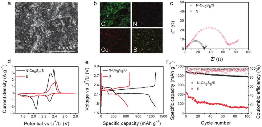
www.advancedsciencenews.com                                                                                                   www.advancedscience.com

Figure 3. The electrochemical performance of the N-Co9 S8 /S electrode compared with that of the S electrode. a) SEM, b) EDS mapping of C, N, Co, and
S, respectively, c) EIS spectra, d) CV curves at the scan rate of 0.1 mV s−1 , e) charge/discharge profiles at the current density of 0.2 A g−1 , and f) cycling
performances.

areal capacity (15 mAh cm−2 ) and a high current density (3 mA                   “deep” cycling of Li metal, especially with a high S loading.[17,27]
cm−2 ), the PCMs host shows a lower plating overpotential of ≈                   So far, most of the works on Li-S batteries focused mainly on the
30 mV compared to ≈ 50 mV of planar Cu (Figure S4, Support-                      sulfur cathode, but didn’t recognize the importance of the Li an-
ing Information). After the initial cycle, the planar Cu shows se-               ode. This work provides useful insights that the full potential of
vere fluctuations during striping, while the PCMs host demon-                     Li-S full pouch cells can be unlocked by optimizing both the Li
strates a much stable striping process. And even after 100 cycles,               anode and sulfur cathode.
the PCMs host still shows a relatively low plating/striping overpo-
tential, and no obvious increase can be observed. Figure 2c shows
the average CE (98.79%) of PCMs after 200 cycles under a high                    2.3. Electrochemical Performance of the N-Co9 S8 /S Electrode
current density with a large Li capacity, which is much higher
than that of the planar Cu (62.32% after 100 cycles). Furthermore,               As discussed above, the full capability of a Li-S full cell depends
even with a much larger areal capacity (30 mAh cm−2 ), the PCMs                  on the synergism between the Li anode and the sulfur cath-
host still displays stable voltage profiles and a relatively high av-             ode. Considering the dissolution of LiPSs in the electrolyte and
erage CE (98.46% after 50 cycles, Figure S5, Supporting Infor-                   the sluggish redox kinetics of S8 ↔ Li2 S, we used the N-Co9 S8
mation). In addition, the morphology of anodes after plating was                 nanoparticles mixed with sulfur (N-Co9 S8 /S) as the cathode. This
measured by SEM. As shown in Figure 2d, the Li@PCMs showed                       is because the N-Co9 S8 nanoparticles can effectively immobilize
an extremely flat surface without any obvious crevices, confirm-                   and catalyze the LiPSs during its conversion, which has been
ing the outstanding reversibility of the dense nucleation on the                 demonstrated in our recent work.[19] The structural and morpho-
PCMs and the high utilization of the PCMs for Li deposition.                     logical characterizations of N-Co9 S8 nanoparticles are shown in
In comparison, Li was sparsely deposited on the planar Cu host,                  Figure S7, Supporting Information. The morphology of the N-
forming a mossy-like loose texture with large crevices, which can                Co9 S8 /S composite is shown in Figure 3a, and the corresponding
be attributed to the growth of Li dendrites (Figure 2e). These can               element mappings of C, N, Co, and S reveal the uniform chemi-
be further confirmed by the cross-sectional SEM images in Fig-                    cal compositions (Figure 3b).
ure 2f,g.                                                                           The electrochemical performances for the obtained N-
   Furthermore, symmetric cells with a large Li deposition ca-                   Co9 S8 /S8 composites were evaluated in half-cells (paired with Li
pacity (15 mAh cm−2 ) were cycled under a high current density                   foil as the counter and reference electrode). The electrochemical
(7.5 mA cm−2 ), in order to evaluate the interfacial stability of Li             impedance spectroscopy (EIS) of the N-Co9 S8 /S electrode shows
metal anodes, see Figure 2h. The Li@Cu symmetric cell exhibits                   a much smaller semicircle compared to that of the S electrode, in-
random voltage oscillations and a significantly shorter cycle life,               dicating a faster charge transfer behavior and improved kinetics
which can be attributed to the Li dendrite growth and the unstable               (Figure 3c). The cyclic voltammetry (CV) curve of the N-Co9 S8 -
interfaces during the repeated plating/striping. In contrast, the                based electrode shows two pairs of redox peaks (O1 , O2 , R1 , and
Li@PCMs symmetric cell demonstrates a stable voltage profile                      R2 , scan rate: 0.1 mV s−1 , Figure 3d). Importantly, a consider-
with a low polarization (only ≈ 100 mV) and an ultralong life (>                 ably mitigated electrochemical polarization and increased peak
300 h) (Figure 2h and Figure S6, Supporting Information). This                   current density can be achieved by the N-Co9 S8 /S electrode, es-
is better than the previously reported results in terms of high cur-             pecially for the transformation from the higher-order LiPSs to
rent density, large Li capacity, and low polarization.[13,26]                    the low order LiPSs (about 2.1 V). This demonstrates the faster
   Importantly, recent studies reveal that the pouch cell failure                kinetic and higher S utilization of the N-Co9 S8 /S electrode (Fig-
may be mainly due to the Li anode degradation because of the                     ure S8, Supporting Information). And this is further supported

Adv. Sci. 2021, 2101182                                              2101182 (4 of 8)       © 2021 The Authors. Advanced Science published by Wiley-VCH GmbH
www.advancedsciencenews.com www.advancedscience.com
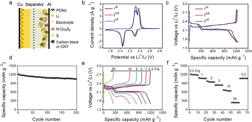
Figure 4. The electrochemical performance of the Li@PCMs||N-Co9 S8 /S full coin cell. a) Schematic illustration of the structure of Li−S full cells, b) CV
profiles (scan rate: 0.1 mV s−1 ), c) charge/discharge curves (current density: 0.2 A g−1 ), d) long-term cycling performance (current density: 0.2 A g−1 ),
e) voltage profiles at different current densities, and f) rate performance. (S mass loading: 1 mg cm−2 , the areal capacity of Li composite: 2 × excess of
S (3.35 mAh cm−2 ), and the thickness of Li composite is about 30 µm.)
by the galvanostatic charge/discharge test (0.2 A g−1 , Figure 3e, cycling stability with a high capacity retention of 1054 mAh g−1
and Figure S9, Supporting Information), where the overpotential over 200 cycles (Figure 4d).
is 200 mV for the S electrode and only 100 mV for the N-Co9 S8 /S The large plating/striping capacity/current density of
electrode, and the specific capacity of the S electrode is about 50% Li@PCMs anode, as well as the unique catalytic function of
to that of the N-Co9 S8 /S electrode. The cycling performances are N-Co9 S8 , can accelerate the kinetic conversion of S8 ↔ Li2 S to
shown in Figure 3f. The N-Co9 S8 /S electrode shows a capacity improve the rate performance of the Li-S full cell. As shown in
retention of 1174 mAh g−1 and an average CE of 99.38% over Figure 4e,f, the full cell could still maintain a high reversible
100 cycles, both of which are much higher than those of the S capacity of 240 mAh g−1 even at an ultrahigh current density
electrode (186 mAh g−1 and 95.25%, respectively). The superior (50 A g−1 ). The specific capacity restores to 1067 mAh g−1 when
cyclability of the N-Co9 S8 /S electrode has been discussed in detail the current returns from 50 to 0.2 A g−1 . It is worth noting, that
in our recent work.[19] the charge/discharge profiles show two well-defined plateaus
at about 2.1 V and low overpotentials even at high current
densities, strongly proving the excellent reaction kinetics. In
contrast, without the N-Co9 S8 additive and the PCMs host, severe
2.4. Electrochemical Performance of the Li@PCMs||N-Co9 S8 /S shuttling behavior, large overpotential, and dramatic capacity
Full Coin Cell decay were observed for the Li@Cu||S full cell (Figure S10,
Supporting Information).
Li-S full cells were then constructed to take advantage of the supe- Despite the high theoretical energy density, however, it is very
rior performances of both Li@PCMs anode and N-Co9 S8 /S cath- challenging to achieve high energy density and high power den-
ode. Figure 4a represents the schematic diagram of the Li-S coin sity simultaneously in a practical Li-S full cell. There are strin-
cell (with 2 × excess Li@PCMs anode). The CV curves of the Li-S gent requirements on the sulfur mass loading (≥ 5 mg cm−2 ), Li
full cell show two couples of reversible reduction (located at 2.3 areal capacity deposition (≥ 10 mA cm−2 ), current density (≥ 10 A
and 2.06 V) and oxidation peaks (located at 2.31 and 2.38 V), as g−1 ), and the E/S ratio. This imposes a great challenge when con-
shown in Figure 4b. The peak at 2.3 V corresponds to the poly- structing the cathode, especially for a pouch cell. The traditional
merization of sulfur into long-chain LiPSs (Li2 Sn , 4 < n < 8), carbon black shows limited electrical and mechanical properties
and the reduction peak at 2.1 V indicates the further reduction in the high S mass loading cathode (compared with the CNTs),
of the long-chain LiPSs to the short-chain LiPSs (Li2 Sn , n ≤ 2). thus cannot be used to maximize the specific capacity of the elec-
The two oxidation peaks at 2.3 and 2.4 V are associated with the trode without sacrificing the power density (Figure S11, Support-
reverse transformation from the short-chain LiPSs to the long- ing Information).
chain LiPSs and finally to the S8 , respectively. We note that the
redox peaks almost overlap for the 2nd and 3rd cycles, which
is the indication of excellent reversibility for the electrochemi- 2.5. Power and Energy Densities of the Li@PCMs||N-Co9 S8 /S
cal processes. The typical charge/discharge profiles are shown in Full Cell
Figure 4c, which are similar to the results from the half cell. The
Li@PCMs||N-Co9 S8 /S full cell is also investigated by the long To solve this issue, the last step in our approach is to mix the
term galvanostatic cycling test. Due to the highly efficient uti- CNTs with N-Co9 S8 /S cathode. The SEM images of this compos-
lization of both anode and cathode, the full cell exhibits excellent ite show a relatively large packing density, and the cross-sectional
Adv. Sci. 2021, 2101182 2101182 (5 of 8) © 2021 The Authors. Advanced Science published by Wiley-VCH GmbHwww.advancedsciencenews.com www.advancedscience.com
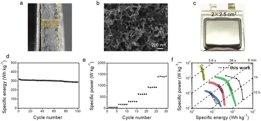
Figure 5. The power and energy densities of the Li@PCMs||N-Co9 S8 /S full cell with high sulfur mass loading. a) Cross-sectional and b) top-view SEM
images of the N-Co9 S8 /S electrode, c) the photo of Li–S pouch cell, d) the specific energy and e) the specific power of the Li-S pouch cell, and f) Ragone
plot comparing various energy storage devices.
view shows a thickness of only 120 µm at 6.3 mg cm−2 (Figure 5a). high energy, high power Li-S batteries for practical applications
The detailed SEM displays that CNTs can support a robust 3D (e.g., electric vehicles/grid storage).
interconnected network (Figure 5b and Figure S12, Supporting
Information). Owning to the excellent electrical and mechanical
properties, the well-dispersed CNTs offer an excellent conductive 3. Conclusions
network and also greatly mitigate the volume change during the
repeated charging/discharging. Figure 5c shows the photo of a In summary, it has been a challenge to realize a practical Li-S
Li@PCMs|N-Co9 S8 /S full pouch cell with a size of 2 × 2.5 cm2 . full (pouch) cell with superior energy density and power density.
And the pouch cell operates at an open-circuit voltage of 2.468 V We propose a biomass-based integral approach to solve this prob-
(Figure S13, Supporting Information). lem. A novel type of biomass-based PCMs have been fabricated by
The results of high mass loadings are very encouraging. The freeze-drying and then carbonizing the watermelon flesh, which
Li@PCMs||N-Co9 S8 /S full pouch cell demonstrates an extremely allows the complete suppression of the Li dendrite growth, and
high energy density of 325 Wh kg−1 when cycled at 0.2 A g−1 . more importantly, a fast Li deposition with large areal capacity.
Even after 100 cycles, the values still maintain at 288 Wh kg−1 This leads to the significant increase of power density in a Li-S
(Figure 5d). When further increased the current density to 5 A full cell, without sacrificing the energy density. Combined with
g−1 , the pouch cell can deliver a relatively high power density of the N-Co9 S8 /S cathode that based on the recently developed N-
466 W kg−1 (after 100 cycles, Figure S15, Supporting Informa- Co9 S8 nanoparticles and the CNTs, the full cells show unprece-
tion). And these results are significantly higher than the previous dented performances even with high active material mass load-
reports.[28,29] It is worth pointing out, that there is still plenty of ings and under low E/S ratios. The state-of-the-art Li@PCMs||N-
room for improvement of the energy density and power density, Co9 S8 /S full pouch cell unlocks the great potentials of both anode
by optimizing the component parameters in a pouch cell.41,44 The and cathode, thus achieving superior energy density and power
specific capacity and areal capacity are shown in Figure S14, Sup- density (325 Wh kg−1 and 1412 W kg−1 , respectively). This work
porting Information, which are larger than the traditional C/S successfully addresses the well-known issue of low power densi-
based cathode, suggesting an improved sulfur utilization. Even ties in Li-S full (pouch) cells, and therefore bringing the maturity
when the sulfur mass loading is increased to 9.8 mg cm−1 , the of Li-S technology to the next level.
specific capacities of both the coin cell and pouch cell still show
appreciable values (Figure S16, Supporting Information). This
specific capacity represents an extremely high level when com- 4. Experimental Section
pared with the previous Li-S full cell works (see Table S1, Sup- Preparation of the Porous Carbon Matrices: A watermelon was cut into
porting Information). small pieces and freeze-dried over 24 h. Then the freeze-dried watermelon
The rate performance of the Li@PCMs||N-Co9 S8 /S full cells pieces were carbonized in a tube furnace under the N2 atmosphere. The
are also impressive (Figure S17, Supporting Information). The procedure consisted of the first heating to 200 °C at 5 °C min−1 and staying
power density of the Li-S full pouch cell is higher than the previ- at 200 °C for 1 h, and then the second heating to 800 °C at 10 °C min−1
ous Li-S studies (< 1000 W kg−1 ).[28] When compared with other and staying at 800 °C for 3 h (to fully carbonize the watermelon). After
the full carbonization, the bright-red watermelon became black pieces. Fi-
main-stream energy storage technologies, an Li@PCMs||N-
nally, these black pieces were ground to powder to form the porous carbon
Co9 S8 /S pouch cell shows significantly improved performances matrices.
in terms of the energy and power densities (Figure 5f).[4,30] There- Preparation of the Porous Carbon Matrices-Based Li Anode: The above-
fore, the biomass-based integral approach enables the design of obtained porous carbon matrices were uniformly coated onto the Cu (with
Adv. Sci. 2021, 2101182 2101182 (6 of 8) © 2021 The Authors. Advanced Science published by Wiley-VCH GmbHwww.advancedsciencenews.com www.advancedscience.com
10 wt% PVDF), and then cut into disc-shaped working electrodes (with a Where C is the capacity (mAh), V is the average output voltage (V), M is
diameter of 12 mm for coin cell, and a size of 2 × 2.5 cm2 for pouch cell, the total weight of the cell (g), and T is time (h).
the mass loading of PCMs on Cu foil is about 0.2 mg cm−2 ). Li metal
melt infusion was carried out in the argon-filled glovebox under sub-ppm
H2 O and O2 (MBRAUN UNI lab) conditions. First, several polished Li Supporting Information
foils were put into a stainless steel crucible and heated on a hotplate at
Supporting Information is available from the Wiley Online Library or from
300 °C. Subsequently, the PCM-based working electrode was put on top of
the author.
the molten Li, and the Li melt was infused into the porous structures and
the interspace among the porous carbons. The color of the electrode sur-
face changes from black to light yellow, indicating the formation of porous Acknowledgements
carbon matrices-Li anode (Li@PCMs). The mass loading of Li can be con-
trolled by the infusion time. Finally, the Li@PCMs anodes were immersed The authors would like to thank Prof. Armin Feldhoff for providing the
into the electrolyte (1.0 m LiTFSI in DOL/DME with 0.1 m LiNO3 ) for 2 SEM, TEM, and XRD facilities.
h to form a stable SEI. Furthermore, Li@PCMs anodes can be also pre-
pared by pre-depositing Li into/onto the PCMs use the half cells. Then the
Li@PCMs anodes can be extracted from the half cells, and used in the Conflict of Interest
symmetrical batteries and full cells, separately.
Preparation of the N-Co9 S8 /S Cathode: The N-Co9 S8 nanoparticles The authors declare no conflict of interest.
were prepared according to our recent work.[19] Sublimed sulfur was im-
pregnated onto the N-Co9 S8 nanoparticles by a melt-diffusion method.
The as-prepared N-Co9 S8 nanoparticles and sulfur were ground together
Data Availability Statement
with a mass ratio of 8:2, and then the mixture was heated at 155 °C for 12 Research data are not shared.
h in a sealed vial to facilitate sulfur diffusion under the argon atmosphere.
The carbon black/S (C/S) composite was prepared using the same method
as the N-Co9 S8 /S composite. The sulfur electrodes were prepared using a Keywords
slurry coating method, 80 wt% N-Co9 S8 /S (or C/S), 10 wt% carbon black
or CNTs, and 10 wt% PVDF (binder) were mixed in NMP to form a slurry biomass-based porous carbon matrices, dendrite-free Li anodes, electric
and coated on Al foil and then dried at 60 °C over 12 h. (Note: the low vehicles/grid storage, Li-S pouch cells, superior energy/power densities
sulfur mass loading electrodes used the carbon black as the conductive
additive, while the high sulfur mass loading electrodes used the CNTs as Received: March 23, 2021
conductive additive. This is because the CNTs can simultaneously boost Published online:
the electrical and mechanical properties of the thick cathodes.)
Characterizations: The morphology and microstructure of the samples
were investigated by SEM (JEOL JSM-6700F) and TEM (JEOL JEM-2100F-
UHR). N2 adsorption/desorption isotherms were determined using an
[1] a) B. Dunn, H. Kamath, J. M. Tarascon, Science 2011, 334, 928. b)
ASAP2050 instrument (Micromeritics Instrument Corp). The surface area
was determined based on the Barrett–Joyner–Halenda (BET) method. X- P. G. Bruce, S. A. Freunberger, L. J. Hardwick, J. M. Tarascon, Nat.
ray diffraction was performed on a PANalytical X-ray diffractometer at a Mater. 2012, 11, 19.
scanning rate of 0.05° s−1 . Raman spectroscopy was carried out on the [2] S. Chu, A. Majumdar, Nature 2012, 488, 294.
inVia Raman spectrometer from Renishaw with a HeNe laser (632.8 nm [3] a) D. C. Lin, Y. Y. Liu, Y. Cui, Nat. Nanotechnol. 2017, 12, 194. b) M.
excitation wavelength). Winter, B. Barnett, K. Xu, Chem. Rev. 2018, 118, 11433. c) N. Nitta, F.
Pouch Cell Assembly: First, both the Li anode and sulfur cathode were X. Wu, J. T. Lee, G. Yushin, Mater. Today 2015, 18, 252.
cut into pieces with a size of 2 × 2.5 cm2 . Second, the Ni tab was pressed [4] Y. Miao, P. Hynan, A. von Jouanne, A. Yokochi, Energies 2019, 12, 1074.
to attach with the cathode and covered with a separator, and then the Al [5] X. L. Ji, K. T. Lee, L. F. Nazar, Nat. Mater. 2009, 8, 500.
tab was pressed to attach the anode. Finally, the Li-S full cell was injected [6] A. Manthiram, Y. Z. Fu, S. H. Chung, C. X. Zu, Y. S. Su, Chem. Rev.
with electrolyte and sealed by Al laminated films. 2014, 114, 11751.
Electrochemical Measurements: Both CR2032-type coin cells [7] G. Y. Zheng, S. W. Lee, Z. Liang, H. W. Lee, K. Yan, H. B. Yao, H. T.
and pouch cells were assembled in an argon-filled glove- Wang, W. Y. Li, S. Chu, Y. Cui, Nat. Nanotechnol. 2014, 9, 618.
box for the electrochemical measurements. 1.0 m lithium [8] a) D. C. Lin, Y. Y. Liu, Z. Liang, H. W. Lee, J. Sun, H. T. Wang, K. Yan,
bis(trifluoromethanesulfonyl)imide (LiTFSI, Sigma-Aldrich) dissolved in J. Xie, Y. Cui, Nat. Nanotechnol. 2016, 11, 626. b) J. Zheng, M. H.
a mixture 1,3-dioxolane (DOL, Sigma-Aldrich) and 1,2-dimethoxyethane Engelhard, D. Mei, S. Jiao, B. J. Polzin, J. G. Zhang, W. Xu, Nat. Energy
(DME, Sigma-Aldrich) (1:1 v/v) with 2 wt% LiNO3 (Sigma-Aldrich) 2017, 2, 17012. c) Y. Zhang, T. T. Zuo, J. Popovic, K. Lim, Y. X. Yin, J.
additive was used as the electrolyte. The E/S ratio for low sulfur mass
Maier, Y. G. Guo, Mater. Today 2020, 33, 56. d) S. Jin, Y. D. Ye, Y. J.
loading (about 1 mg cm−2 ) is about 4 µl mg−2 , for high sulfur mass
Niu, Y. S. Xu, H. C. Jin, J. X. Wang, Z. W. Sun, A. M. Cao, X. J. Wu, Y.
loading (about 6.3 and 9.8 mg cm−2 ) it is about 1.5 µl mg−1 .[29] Celgard
Luo, H. X. Ji, L. J. Wan, J. Am. Chem. Soc. 2020, 142, 8818.
2400 membrane was used as the separator. The cycling performances
of the cells were measured by galvanostatic charge/discharge within the [9] a) Y. Yang, G. Y. Zheng, Y. Cui, Chem. Soc. Rev. 2013, 42, 3018. b) A.
voltage window of 1.7–2.8 V versus Li/Li+ (LAND CT 2001A). CV and EIS Manthiram, S. H. Chung, C. X. Zu, Adv. Mater. 2015, 27, 1980. c) G.
measurements were conducted by using Metrohm Auto-lab. M. Zhou, H. Z. Tian, Y. Jin, X. Y. Tao, B. F. Liu, R. F. Zhang, Z. W. Seh,
The Evaluation of Energy/Power Densities: The energy density (Eg ) and D. Zhuo, Y. Y. Liu, J. Sun, J. Zhao, C. X. Zu, D. S. Wu, Q. F. Zhang, Y.
power density (Pg ) can be calculated by using the following equations: Cui, Proc. Natl. Acad. Sci. U. S. A. 2017, 114, 840.
[10] a) G. Babu, N. Masurkar, H. Al Salem, L. M. R. Arave, J. Am. Chem.
CV Soc. 2017, 139, 171. b) Z. Sun, J. Zhang, L. Yin, G. Hu, R. Fang, H.
Eg = (1) M. Cheng, F. Li, Nat. Commun. 2017, 8, 14627. c) L. Li, L. Chen, S.
M
Mukherjee, J. Gao, H. Sun, Z. B. Liu, X. L. Ma, T. Gupta, C. V. Singh,
W. C. Ren, H. M. Cheng, N. Koratkar, Adv. Mater. 2017, 29, 1602734.
Eg d) L. Luo, S. H. Chung, H. Y. Asl, A. Manthiram, Adv. Mater. 2018, 30,
Pg = (2) 1804149.
T
Adv. Sci. 2021, 2101182 2101182 (7 of 8) © 2021 The Authors. Advanced Science published by Wiley-VCH GmbHwww.advancedsciencenews.com www.advancedscience.com
[11] a) X. E. Wang, R. Kerr, F. F. Chen, N. Goujon, J. M. Pringle, D. Mecer- [20] a) S. H. Park, P. J. King, R. Y. Tian, C. S. Boland, J. Coelho, C. F. Zhang,
reyes, M. Forsyth, P. C. Howlett, Adv. Mater. 2020, 32, 1905219. b) Y. P. McBean, N. McEvoy, M. P. Kremer, D. Daly, J. N. Coleman, V. Ni-
Cui, Acta Phys.-Chim. Sin. 2019, 35, 661. c) C. Z. Zhao, H. Duan, J. Q. colosi, Nat. Energy 2019, 4, 560. b) Y. P. Liu, X. Y. He, D. Hanlon, A.
Huang, J. Zhang, Q. Zhang, Y. G. Guo, L. J. Wan, Sci. China: Chem. Harvey, U. Khan, Y. G. Li, J. N. Coleman, ACS Nano 2016, 10, 5980. c)
2019, 62, 1286. Y. P. Liu, X. Y. He, D. Hanlon, A. Harvey, J. N. Coleman, Y. G. Li, ACS
[12] a) M. Armand, J. M. Tarascon, Nature 2008, 451, 652. b) A. Mauger, Nano 2016, 10, 8821.
C. M. Julien, A. Paolella, M. Armand, K. Zaghib, Materials 2019, 12, [21] a) L. Liu, Y. X. Yin, J. Y. Li, N. W. Li, X. X. Zeng, H. Ye, Y. G. Guo, L. J.
3892. c) S. Afyon, K. V. Kravchyk, S. T. Wang, J. van den Broek, C. Wan, Joule 2017, 1, 563. b) L. F. Chen, Z. H. Huang, H. W. Liang, W.
Hansel, M. V. Kovalenko, J. L. M. Rupp, J. Mater. Chem. A 2019, 7, T. Yao, Z. Y. Yu, S. H. Yu, Energy Environ. Sci. 2013, 6, 3331.
21299. d) Y. Yao, H. Y. Wang, H. Yang, S. F. Zeng, R. Xu, F. F. Liu, P. [22] a) A. Sadezky, H. Muckenhuber, H. Grothe, R. Niessner, U. Poschl,
C. Shi, Y. Z. Feng, K. Wang, W. J. Yang, X. J. Wu, W. Luo, Y. Yu, Adv. Carbon 2005, 43, 1731. b) M. Sevilla, A. B. Fuertes, ACS Nano 2014,
Mater. 2020, 32, 1905658. 8, 5069.
[13] H. Y. Li, Z. Cheng, A. Natan, A. M. Hafez, D. X. Cao, Y. Yang, H. L. [23] H. D. Yuan, T. F. Liu, Y. J. Liu, J. W. Nai, Y. Wang, W. K. Zhang, X. Y.
Zhu, Small 2019, 15, 1804609. Tao, Chem. Sci. 2019, 10, 7484.
[14] W. L. Cai, G. R. Li, D. Luo, G. N. Xiao, S. S. Zhu, Y. Y. Zhao, Z. W. Chen, [24] P. Wang, B. J. Xi, M. Huang, W. H. Chen, J. K. Feng, S. L. Xiong, Adv.
Y. C. Zhu, Y. T. Qian, Adv. Energy Mater. 2018, 8, 1802561. Energy Mater. 2021, 11, 2002893.
[15] B. E. Conway, Electrochemical Supercapacitors: Scientific Fundamentals [25] a) H. S. Wang, D. C. Lin, J. Xie, Y. Y. Liu, H. Chen, Y. B. Li, J. W. Xu,
and Technological Applications, Springer Science & Business Media, G. M. Zhou, Z. W. Zhang, A. Pei, Y. Y. Zhu, K. Liu, K. C. Wang, Y. Cui,
Berlin 2013. Adv. Energy Mater. 2019, 9, 1802720. b) R. Zhang, X. Chen, X. Shen,
[16] K. L. Zhu, C. Wang, Z. X. Chi, F. Ke, Y. Yang, A. B. Wang, W. K. Wang, X. Q. Zhang, X. R. Chen, X. B. Cheng, C. Yan, C. Z. Zhao, Q. Zhang,
L. X. Miao, Front. Energy Res. 2019, 7, 123. Joule 2018, 2, 764.
[17] L. L. Shi, S. M. Bak, Z. Shadike, C. Q. Wang, C. J. Niu, P. Northrup, H. [26] F. Pei, A. Fu, W. B. Ye, J. Peng, X. L. Fang, M. S. Wang, N. F. Zheng,
K. Lee, A. Y. Baranovskiy, C. S. Anderson, J. Qin, S. Feng, X. D. Ren, ACS Nano 2019, 13, 8337.
D. Y. Liu, X. Q. Yang, F. Gao, D. P. Lu, J. Xiao, J. Liu, Energy Environ. [27] D. P. Lv, J. M. Zheng, Q. Y. Li, X. Xie, S. Ferrara, Z. M. Nie, L. B. Mehdi,
Sci. 2020, 13, 3620. N. D. Browning, J. G. Zhang, G. L. Graff, J. Liu, J. Xiao, Adv. Energy
[18] a) X. Y. Huang, J. J. Xue, M. Xiao, S. J. Wang, Y. N. Li, S. C. Zhang, Mater. 2015, 5, 1402290.
Y. Z. Meng, Energy Storage Mater. 2020, 30, 87. b) C. Barchasz, [28] H. Nagata, Y. Chikusa, Energy Technol. 2016, 4, 484.
L. Boutafa, E. Mayousse, B. Chavillon, Electrochim. Acta 2018, 292, [29] W. J. Xue, Z. Shi, L. M. Suo, C. Wang, Z. A. Wang, H. Z. Wang, K. P. So,
974. A. Maurano, D. W. Yu, Y. M. Chen, L. Qie, Z. Zhu, G. Y. Xu, J. Kong, J.
[19] Y. Liu, S. Ma, L. Liu, J. Koch, M. Rosebrock, T. Li, F. Bettels, T. He, Li, Nat. Energy 2019, 4, 374.
H. Pfnür, N. C. Bigall, F. Ding, L. Zhang, Adv. Funct. Mater. 2020, 30, [30] T. Q. Lin, I. W. Chen, F. X. Liu, C. Y. Yang, H. Bi, F. F. Xu, F. Q. Huang,
2002462. Science 2015, 350, 1508.
Adv. Sci. 2021, 2101182 2101182 (8 of 8) © 2021 The Authors. Advanced Science published by Wiley-VCH GmbHYou can also read