A Multi-Core Basic Software as Key Enabler of Application Software Distribution - ERTS 2018
←
→
Page content transcription
If your browser does not render page correctly, please read the page content below
A Multi-Core Basic Software as Key Enabler of
Application Software Distribution
André Göbel Denis Claraz
Continental Automotive GmbH, Continental Automotive France SAS
P.O. Box 100943 1, av. Paul Ourliac, BP 1149
D-93009 Regensburg 31100 Toulouse
Germany France
Email: andre.goebel@continental-corporation.com Email: denis.claraz@continental-corporation.com
Abstract—In the last 20 years, functional evolution in the I. M ULTI -C ORE N EEDS IN THE P OWERTRAIN D OMAIN
automotive Powertrain has been motivated by three main
pillars: low CO2 emissions, low particle emissions and increase A. Introduction
of torque throughput. In addition to these permanent objectives After introduction of the first 32bit automotive micro-
(e.g. Euro 7 standard), new constraints are rising up, like
integrated transmission systems, electrification, autonomous controllers (e.g. Motorola MPC555, MPC563, Infineon
driving, connectivity as well as changed domain architectures. Tricore TC1796) the hardware (HW) vendors answered to the
growing computation needs with increasing clock frequencies,
Finally, new complexities have to be handled, which require optimized architectures and dual controller solutions. Thus
today 6 times as much computation power as 15 years ago, when the power supplies and cooling efforts were similarly growing
32 bits controllers were introduced (e.g. former Motorola MPC
563 @ 40MHz). This demand is answered by the introduction and the only way out was the introduction of dual-core and
of multi-core micro-controller architectures designed for the a bit later multi-core micro-controller architectures which
automotive environment. And the trend of requiring additional offered the desired computation power basing on lower
computation power will continue in the future where one frequencies (e.g. Infineon Aurix TC2xx). In addition the
might step forward towards more powerful multi-core or even hardware technology went down towards 40nm. In further
many core systems. But the development of powerful hardware
architectures does not release software architecture from evolution steps the HW architectures got optimized, but still
careful usage of system resources. This is because a multi-core needs to be optimized for the future again in order to react to
system can be used in an efficient way only if a high rate of the increasing computation demands one can see in a forecast
parallelization can be achieved according to Amdahl’s law[8]. to the next decade of Powertrain applications. So it can be
estimated already today that the needed computation power
Even if AUTOSAR [4] allows a partitioning of software
components (SWC) across cores, it does simply not consider a in 2022 will be at least doubled compared to today.
multi-core basic software (BSW) until today. Instead it phrases Nevertheless, multi-core architectures do not provide
just concept ideas not realized in the standard. So it is the automatically a gain of performance, particularly for highly
task of this paper to give an overview about the possibilities coupled systems with strong HW interaction as well as hard
of the AUTOSAR standard and to sketch an alternate solution real-time requirements. It might even be counter-productive,
based on the AUTOSAR foundation offering a distributable
BSW across cores which allows a distribution of not only a if it is not properly handled. So it is essential for the effective
SWC but even the individual runnables of it. It will explain usage of these architectures to achieve freely distributable
how the BSW itself is distributed, and how the access to the Application SWC along cores by single runnables what has
peripherals from different cores is made possible. Furthermore already been presented in a previous ERTS2 edition [6]. But
a concept of core abstraction will be described, allowing to for that a real multi-core BSW is required as a key enabler.
share even the same task architecture between projects based on
different micro-controllers. Consequently, the paper will propose Besides the main focus on efficiency, a maximum freedom
a qualification of the BSW into 3 multi-core conformance classes. in the allocation of the ASW runnables is required, knowing
that many of them need an access to the HW peripherals. Of
The principles described in this contribution are applied in course, locking other cores while accessing the peripheral is
the daily work in our Powertrain projects, and are already in not an option, like enforcing all ASW components with HW
production since 2016 for a central Powertrain controller of
a German OEM, and since 2017 for an engine system of a interface to be integrated on one and the same core.
french OEM. At the date of publication, other engine systems
applications and hybrid systems based on this concept are in
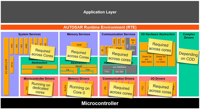
production, and further ones are planned for 2018. B. The layered Architecture
Index Terms—Multi-core, Real-time system, AUTOSAR, Au- A classical embedded software (SW), as it is defined for
tomotive, Embedded software, BSW, Basic software, CPU-Load, example by the AUTOSAR standard, is typically split into
Powertrain four main parts as shown in Figure 1: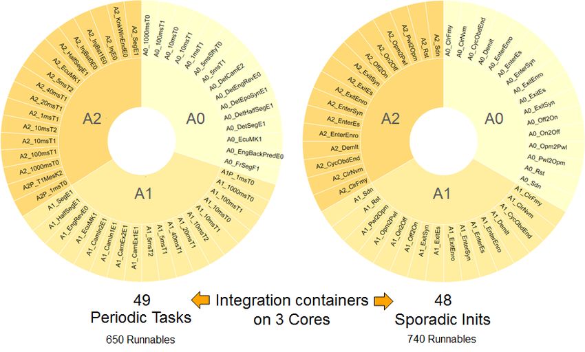
•   The high level applicative SW (ASW) which is designed         core context), and a new process cares about the challenging
      in a way that it can be easily reused across system           multi-core issues such as increased scheduling complexity
      platforms, and across project configurations, e.g. for 4, 6   (parallelism, chaining, synchronization), increased integration
      cylinders, gasoline, diesel or electric engines. The ASW      complexity (1500 runnables to be integrated in 100 containers)
      is named as SWC according to AUTOSAR.                         and concurrent accesses to shared resources.
  •   A runtime environment (RTE) which enables the inter-          On the one side, the concurrent accesses to shared memory,
      facing in between SWC and BSW modules.                        has been solved in the Powertrain domain of Continental by
  •   The BSW which enables the re-usability of ASW across          the introduction of an adequate and optimized process based
      different HW platforms. For that, the BSW gives access        on an automatic protection, new architectural concepts (like
      to the core services and peripherals, abstracting different   e.g. core synchronized transitions) and protecting the SW by
      micro-controllers as well as connected peripherals such       the use of buffers [6]. So a slightly prepared software can
      as ASICs and FPGAs of different vendors.                      be freely distributed across cores, tasks, as well as multiple
  •   The micro-controller hardware which is connected by the       contexts.
      BSW towards RTE and application.                              On the other side, the concurrent accesses to the shared HW
                                                                    peripherals is ensured by a well prepared BSW. This means
                                                                    in effect, the ASW will be free to access HW resources from
                                                                    many different places, in one or the other direction (input
                                                                    capture, output control) or sometimes a mixture of both.
                                                                    D. Distributing Application and Basic Software
                                                                       For efficient use of single, multi or even many core system it
                                                                    requires a powerful and flexible BSW which provides commu-
                                                                    nication, diagnosis and input/output features to the application
                                                                    and which is scalable to all kinds of core configurations. In a
                                                                    simplified view the BSW connects the ASW to the hardware
                                                                    to allow a re-use of the ASW on different hardware platforms.

                Figure 1. The ICC3 AUTOSAR BSW

C. Running Multi-Core-Ready Applications
   From application point of view, it is a valid wish to run
the software on the system independently whether it is a
single or multi-core implementation. Anyway, it is not possible
to fix a distribution from the beginning of the project, till
the start of production, for various reasons. And it is even
less possible to force a common core distribution between
different projects using different HWs, following different
schedules, but nevertheless sharing common SWCs. To reach

                                                                                 Figure 3. A possible but inefficient Solution

                                                                       In case the BSW is not well prepared for multi-core, and
                                                                    is accessible only from one core, one can easily end-up
                                                                    in a situation, where all ASW runnables which directly or
                                                                    indirectly access to a BSW interface and through it to a HW
                                                                    resource have to be located on the same core, where the
                                                                    BSW resides. This results in a long calculation chain and
                                                                    in strong integration constraints on the ASW runnables as
                                                                    already described in the introduction and shown in Figure 3.
                                                                    Furthermore, as many recurrences are required, like described
                                                                    in Figure 2, this may result in difficult interleaving situations.
                                                                    To avoid such inefficient situation, a real prepared BSW is
                  Figure 2. Real Time Partitioning                  required. But before defining this ideal multi-core BSW, one
                                                                    needs to understand the boundary conditions defined by the
this goal, the SWCs are designed independently of any core          AUTOSAR standard. In addition the available micro-controller
association (but slightly prepared compared to legacy single        architectures along the used platform have to be considered.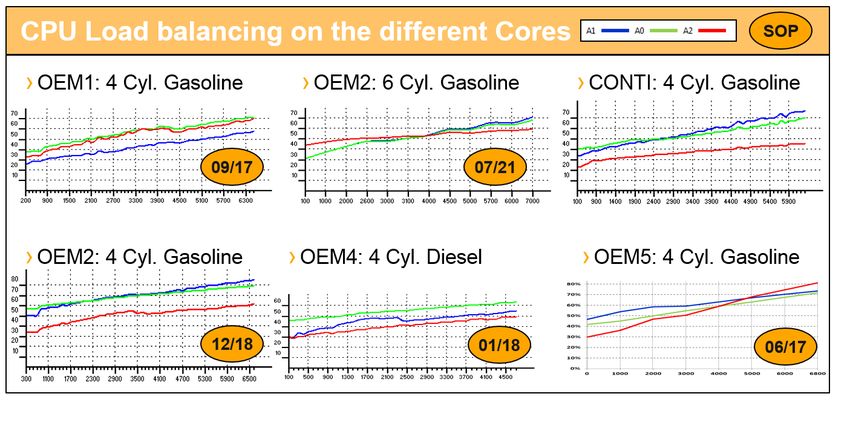
II. F ROM AUTOSAR TO A M ULTI -C ORE BSW
A. AUTOSAR versus Multi-Core
   Originally AUTOSAR [1] was developed for single core
control units, even if the standard considered to combine
such ECUs with a bus system in between. Each control
unit is defined to contain exactly one application running
on one operating system (OS) instance. The first extension
of the AUTOSAR standard concerning multi core was only
supporting the distribution of the ASW to different cores.
Thereby at least one OS-Application is allocated to one core
and all items of a software component (runnables, non volatile
data blocks, exclusive areas) need to be solely implemented          Figure 4. Software Distribution across Control Units using AUTOSAR
with OS resources belonging to exactly this OS-Application.
The communication in between should be done using the
runtime-environment RTE / Inter OS Communication (IOC)
and the BSW was assumed to run on a single core while all
accesses shall be performed exactly by this core. The IOC is
defined for that use case as highly generic mechanism offering
a superset of functionality to cover all possible use cases.
In a second evolution step [2] the AUTOSAR standard sup-
ports additionally the distribution of the BSW to different
cores. With this extension, the Schedule Manager part of the
RTE provides features for the cross core inter and intra BSW
module communication. Additionally the MemMap specifica-
tion [5] contained in the AUTOSAR standard from version
4.2.2 [3] onwards allows an allocation of symbols on different        Figure 5. Software Distribution across Cores using pure AUTOSAR
cores. This is an important prerequisite for a multi-core BSW.
A drawback of this second evolution was the low profoundness
of standardization. On the one hand this supports various          BSW (see Figure 5) one would cause access conflicts to the
vendor specific extensions but on the other hand it drastically    hardware as the BSW is simply existing twice. The CPU load
decreases the interoperability and performance of BSW from         would mainly be influenced in this scenario by the load on the
different vendors in a multi-core ECU.                             bus system at the intersection of the individual cores towards
The biggest problem remaining in the AUTOSAR BSW ar-               the hardware resources.
chitecture is the synchronous architecture which leads to an         To overcome this situation one would need to split the
interface design where it is expected that the called operations
act immediately returning the final status. Instead multi-core
requires asynchronous operation to avoid blocking of cores
what is contradictive to the synchronous interface architecture
of AUTOSAR. As a conclusion a rework of the interfaces
towards asynchronous interfaces with according status opera-
tions or feedback signals would be required.

B. Capabilities of a pure AUTOSAR Implementation
   Looking at the AUTOSAR standard there is a RTE defined
to connect application and BSW to allow a mapping of
interfaces in between the layers and even OS-Applications.
This allows to distribute ASW to different control units to use       Figure 6. Software Distribution across Cores using AUTOSAR RTE
the available computation power across the car in an efficient
way as shown in Figure 4. But what is looking very promising       BSW into parts which are assigned to cores with individual
on car level might tempt one to apply it inside a multi-           OS-Applications still using the RTE provided communication
core micro-controller. But even if this is technically possible    according to Figure 6. This means, that the transfer of requests
from AUTOSAR perspective by using one OS-Application per           to the right core towards the BSW would be done using the
core, this shows various drawbacks such as high CPU load           RTE invoking IOC. This avoids access conflicts on the periph-
consumption, memory overhead or unnecessary blocking of            eral side, but still causes a high communication overhead in
cores or interrupts. Especially when considering a duplicated      between the cores. A better alternative would be one of the
following ideas:                                                      robustness reasons. Instead it is better to solve the root cause
   • Transfer the application call chain to the core where the        by generally preventing ”blocking waits” by the architecture
      BSW resides (see Figure 3)                                      definition even if the implementation then does not comply to
   • Transfer the call on BSW level as an implementation              the AUTOSAR standard any more.
      variant of the AUTOSAR BSW distribution specification
The conclusions out of both approaches are on the one hand
that the first idea is contradictive in terms of CPU load
distribution across cores, causing high task response times
until execution chains can be completed. On the other hand the
second idea could not be exactly implemented as the standard
describes. This is because AUTOSAR requires an identical
behaviour of the almost synchronous interface operations
independent of the listed call scenarios below:
   • call on a single core system
   • call from the same core than the one the BSW resides
   • call from a different core than the one the BSW resides
As a consequence, the synchronous operations defined in the
standard would block several cores when getting called, what
again has a high influence on the CPU load. As an example,
a simple operation of the AUTOSAR PWM driver shall be                           Figure 7. Blocking Behaviour of AUTOSAR PWM
used, namely Pwm SetDutyCycle(), what is specified in table
Table I.
                                                                      C. The ideal Basic Software
                          Table I                                       Keeping the vision of distributing the application by
           AUTOSAR P WM S ET D UTY C YCLE OPERATION
                                                                      runnable to different cores one needs to have an ideal BSW
   Service Name:                   Pwm SetDutyCycle                   which can be called from any core without taking care on
     Reference:                     SWS Pwm 00097                     which core it is really running on. This for sure needs to
      Syntax:                      Pwm SetDutyCycle(
                          Pwm ChannelType ChannelNumber,              be done without duplicating the BSW according to Figure 5
                                    uint16 DutyCycle)                 but instead creating a BSW which offers interfaces on any
    Sync/Async:                        Synchronous                    core implementing a kernel on a single core only. In between
    Re-entrancy:        Re-entrant for different channel numbers
    Description:    Service sets the duty cycle of the PWM channel.

   Following the AUTOSAR specification it is mandatory to
implement the operation as synchronous. That leads to the
drawback that one needs to implement a blocking wait to the
Pwm SetDutyCycle().
As shown in Figure 7, the ASW is allocated on Core 1 and
needs to trigger a PWM output, using a distributed BSW.
The ASW calls the according Pwm SetDutyCycle() operation,
which then needs to transfer the control flow to core 2, which
is in the given example the BSW core. The operation on core
1 then waits for completing the triggered action on the BSW
core which receives and processes the request in parallel. Af-
terwards an according status will be set to notify the interface                  Figure 8. Access to the ideal Basic Software
operation on core 1 that the operation is finished which then
can unlock the ”blocking wait” and continues to operate. The          the interfaces and the kernel the control and data flow can
drawback is obvious as two cores are blocked and no parallel          be realized using a module specific implementation for
execution can take place at this time. This is especially difficult   an optimal core resource consumption. Thus the BSW is
in co-operative or partly pre-emptive task environments which         reachable by any core without the need of routing the transfer
are typically used in Powertrain applications. Only pre-emptive       by the RTE and bypassing the OS-Application approach.
environments using extended tasks could help here paying the          That is as shown in Figure 8. For that purpose it is first of
price with a high CPU load and memory overhead for the                all important to identify which BSW modules have to be
additional operating system features reducing the ”symptoms”          reachable across cores and which ones can remain as single
(instead of the root cause) of the blocking wait. Furthermore,        core module following the AUTOSAR defined architecture
extended tasks and therefore wait states, are not an option for       as shown in Figure 9 . This is important as some BSW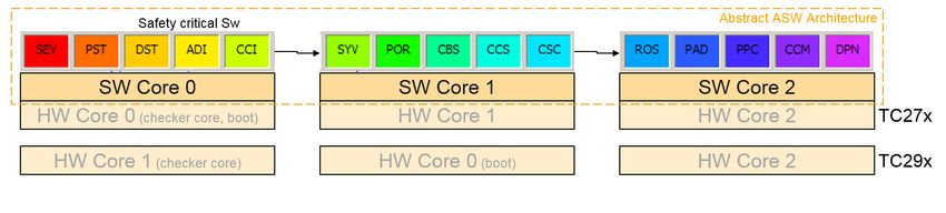
modules might be finally offered on one core only as these
are acting on hardware peripherals which have to be accessed
exclusively. For all BSW modules identified as multi-core

                                                                            Figure 10. Direct Data Access using Adc ReadGroup()

                                                                    is synchronously finished. If the application instead needs to be
                                                                    notified about the finished PWM output an according feedback
               Figure 9. Core Scope of BSW Modules                  signal needs to be used which can be generated at the PWM
                                                                    edge the value is transferred to the output peripheral. This
relevant one needs to decide for an according implementation        feedback signal would then start a system event (task) on a
behind the user interface which ensures a suitable cross            defined core according to Figure 12.
core communication. For that purpose, a set of generic
libraries is offered which provides a generic implementation
of according multi-core mechanisms to the BSW modules.
But for what kind of implementation one shall decide? And
what paradigms shall be used as basis for the design choice?

   1) The first BSW paradigm - A Blockade Free BSW:
Generally an ideal realization requires that the BSW runnables
can be triggered asynchronously to avoid any kind of spin-
lock situations. So, all synchronous operation calls need to
be considered as a simple buffer access. All asynchronous
operation calls need to be treated as requests to be queued
to the kernel and all blocking synchronized operation calls                   Figure 11. Pwm SetDutyCycle() as Fire & Forget
need to be migrated towards asynchronous operations with
an according feedback signal. Out of that considerations the
following two generic design patters are derived:
   • Direct data (or peripheral) access for synchronous reading
      and writing of data
   • Passing control (and data) flow for asynchronous actions
      with optional feedback
While the first design pattern for direct data access shall
be applied especially for BSW drivers providing or writing
atomic data such as ADC or DIO, what is shown in the
Adc ReadGroup() example Figure 10. It can also be applied
for drivers writing non atomic data such as SPI where a
collision during the write and read is very unlikely. For the SPI
case it might be required to introduce a semaphore to avoid
data inconsistency in the unlikely case of a collision.                        Figure 12. Pwm SetDutyCycle as Fire & Reply
  The second design pattern for passing control and data
flow with optional feedback is ideal for solving the PWM              2) The second BSW paradigm - An optimal cross Core
implementation issue (see Figure 7) as it decouples the ASW         Communication: This paradigm requires to implement the
control flow from the driver operation performing the final         design patterns out of the first paradigm to realize a man-
output as shown in Figure 11. As a precondition the ASW             agement of data and control flow across cores. The multi-core
SWC calling the Pwm SetDutycycle() shall not perform an             mechanisms and design patterns derived have to be carefully
action which depends on the finished PWM output. In other           used as too much protection can again have a negative impact
words the application shall not expect that the PWM operation       on the overall CPU load and memory consumption. So any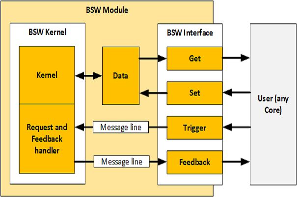
multi-core pattern shall be used in a minimal scope only (e.g.
just protecting a minimal amount of C instruction inside a
function). Furthermore the implementation of the multi-core
mechanisms shall cover a small set of use cases only to
be optimized for exactly one purpose to gain much better
performance than globally designed mechanisms like IOC. As
a consequence a set of multiple design patterns and library
implementations is required to cover the required use cases of
a multi-core BSW.
So, as one typical example, a hardware optimized message
passing mechanism, named ”MEPA” is available in the Pow-
ertrain platform as alternate to generic mechanisms such as the
AUTOSAR IOC. MEPA offers the following send operations:
   • Transfer a control flow to another core
                                                                                       Figure 13. BSW Multi-Core approach
   • Transfer a control flow extended by a simple 32bit
      variable
   • Transfer a control flow extended with a pointer to a user
                                                                       as trigger with optional feedback, and any simple data transfer
      specific data package                                            is realized as a kind of atomic (not interruptible) access as
On receiver side one can either:                                       sketched in Figure 13. According to that, it is possible that
   • Trigger an interrupt containing the receiver code                 any user can call the BSW directly without taking care about
   • Trigger a system event (task)                                     the core on which it is finally executed.
   • Poll the event in a recurrent time grid

Thereby the order of incoming messages is kept and so the              E. BSW Examples
inputs are serialized. Furthermore the channels are individual            Before giving a set of examples related to the previously
for each BSW module, means there exists at least one                   defined BSW multi-core types it has to be considered that
channel per BSW module. Implementing all user operations               there is no 1:1 mapping in between a function stack or
on receiver side on the same interrupt or task level one can           cluster to exactly one multi-core type. Instead it is typically a
furthermore save efforts for re-entrancy protection as the             combination of multiple types. So it is important to design the
tasks or interrupts can not interrupt themselves. So disabling         function stack or cluster in a way that all interfaces towards
interrupts is simply not required any more.                            other BSW function stacks, BSW clusters or SWC comply
                                                                       to type 1 and 2. Instead type 3 shall be used inside the
                                                                       function stack or cluster only. Finally the following three
D. BSW Design for Multi-Core
                                                                       typical examples shall be given:
   To map the right functionality on the right core, the BSW              1) Example 1 - Memory Stack - Type 1 and Type 3: The
has to be analysed following the AUTOSAR stack approach                Memory Stack (MEM) is required for any kind of memory
in order to identify which of the BSW modules are interfacing          reprogramming. The non-volatile memory manager (NVM)
to other clusters or ASW software components. Additionally,            especially cares about the storage of data for usage during the
it needs to be analysed, which BSW modules are used inside             following driving cycles. The NVM interfaces are required at
an AUTOSAR stack only. For that purpose the considerations             any core and are provided as global (shared) code. Instead the
shown in Figure 9 shall be re-used. Doing that, it needs to be         kernel is in local scope of core 1. The used modules such
respected that clusters or even parts of a functional stack shall      as FEE and FLS are available on this core exclusively. This
be distributable across cores. Out of the analysis the following       ensures that the data flash consistency can be managed on
BSW multi-core types can be derived:                                   NVM kernel level. The NVM architecture shown in Figure 14
   • Type 1: BSW modules with interfaces available on any              visualizes the usage of the MEPA service which is used to
      core and one kernel on a single core (e.g. DEM, FIM,             transfer the incoming requests of the consumers to the NVM
      MCAL drivers)                                                    kernel. The requests then are polled by the kernel in a defined
   • Type 2: BSW modules with a distributed kernel executed            recurrence, e.g. for writing ”on the fly data” to the data flash.
      per core (e.g. DIO, exception handler, interrupt driver,         If desired the consumer can be notified about the finished
      watchdog)                                                        request by using a MEPA callback, which this time triggers
   • Type 3: BSW modules available on a single core only               an according feedback task.
      (e.g. flash driver), the interfaces are not globally available      2) Example 2 - Communication Stack - Type 1 and Type 3:
The transfer of data and control flow in between the BSW               The communication stack provides communication services
interfaces and cores is realized according to the multi-core           towards the application, where the COM interfaces for inter-
paradigms inside the relevant BSW modules or at least inside           system-communication need to be provided on any core. The
the BSW stack. So any kind of control flow transfer is realized        kernel implementation and even specific networks such as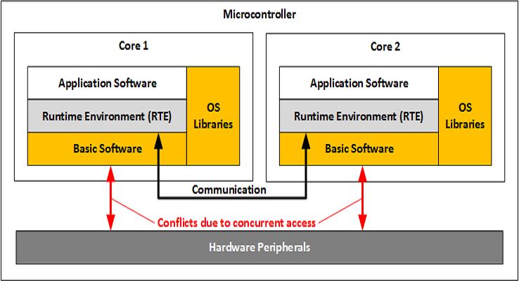
is implemented providing user interfaces as global (shared)
                                                                  code which can be executed on any core providing access
                                                                  to the acquired ADC values. The ADC kernel instead is
                                                                  provided core local and called by a task to recurrently trigger
                                                                  the auto-scan conversion. The PWM instead is implemented
                                                                  basing on MEPA, similarly to the NVM shown in example
                                                                  1 and is already sketched in the chapter ”The first BSW
                                                                  paradigm - A Blockade Free BSW”. The DIO driver is a
                                                                  special case, as the overhead of implementing any multi
                                                                  core implementation would cause much more CPU resource
                                                                  overhead as the resulting bus conflicts in case of concurrent
                                                                  accesses in between the cores. So each core calls a global
                                                                  (shared) code of the DIO module which then directly accesses
                                                                  the hardware peripheral, as the peripheral can be accessed in
      Figure 14. Memory Stack - NVM Architecture (simplified)     an atomic way.

CAN, Ethernet or Flexray are realized on individual cores.
The motivation for this is a load distribution of the different
networks across cores. As shown in figure Figure 15 the central
part is the PDU router which is generated per core, routing
the messages in between the different networks, the COM
as user interface and the diagnostic communication manager
(DCM). The PDU router consists finally of core individual
local implementations using the MEPA service in between
to cross the core boundaries. The network stacks (e.g. CAN,
Flexray, Ethernet) are provided as core local implementations
not accessible by other cores as the only interface exists
towards the PDU router. The DCM is also connected to the
PDU router, but allocated on the same core than the network
used for diagnostic communication. This is to reduce the                 Figure 16. MCAL Peripheral Driver Example (simplified)
amount of messages and so the CPU load consumption of
interrupts which would be required to transfer the calls across          III. C ORE A BSTRACTION AND M ULTI -C ORE
core boundaries. The COM module is available as global                            C ONFORMANCE C LASSES
(shared) code which is scheduled per core with an individual      A. Abstracting Cores
message configuration. So finally the messages are routed via
PDU router and COM to the correct SWC.                               To make the BSW and application more independent a
                                                                  further valuable step is to introduce a core abstraction ap-
                                                                  proach that allows a core clustering to separate calculation
                                                                  domains, e.g. for the purpose of integrating different products
                                                                  to one box, as engine and transmission control, or to separate
                                                                  computation clusters depending on the HW implementation.
                                                                  Furthermore it helps the ASW and BSW developers to think
                                                                  independent of the core which is typically linked to a hard-
                                                                  ware implementation as the same core number could have a
                                                                  different meaning and available features on a different HW. To
                                                                  distinguish and identify the cores, the core abstraction defines
                                                                  an own naming scheme consisting of two characters. The first
                                                                  character defines the calculation domain with the values ’A’
                                                                  to ’Z’, while the second character defines the abstract core
                                                                  number from ’0’ to ’9’. Typically a multi-core micro-controller
           Figure 15. COM Stack Architecture (simplified)         consists of one domain ’A’, with e.g. 3 cores, but there might
                                                                  be future architectures providing several domains, like caused
   3) Example 3 - MCAL - Type 2 and Type 3: The MCAL              by a hardware bridge in between two groups of cores.
(Micro Controller Abstraction Layer) provides basic functions     As a typical example of today’s multi-core architectures three
such as ADC, PWM, Digital I/O etc. which have to provide          abstract cores are integrated in one calculation domain with
interfaces to any core (see Figure 16). The ADC module            according attributes what are: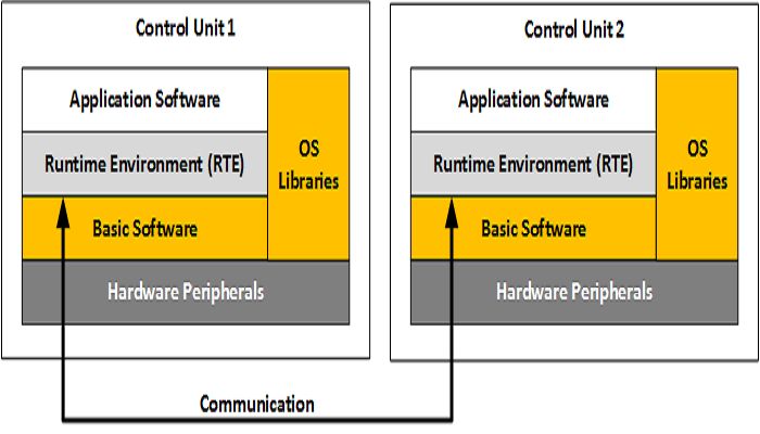
•   A0 - Safe Core with safe and unsafe partitions for safety    C. Multi-Core Conformance Classes
      related ASW and BSW
                                                                      Similarly to the ICC classification, a proposal of multi-core
  •   A1 - Unsafe communication core
                                                                   conformance classification (MCC) is made: It corresponds to
  •   A2 - Unsafe alternate core
                                                                   different implementation levels of multi-core concepts, from
The application and BSW is assigned to the cores basing on         low to high level of achievement. The objective here is not on
affinities to e.g. distribute the BSW load or to ensure that       modularity / re-usability point of view like the implementation
safety software is calculated on a lock-step CPU. On the           conformance classes (ICC), but rather on the efficiency and
ASW side, this abstraction concept allows to share the same        abstraction, for the ”customers” of the BSW layer (e.g. ASW
architecture (task system) between projects using different        SWC, BSW Complex Device Drivers (CDD)) towards their
controllers, where for example, not all cores have the same        multi-core constraints. Basically, if the AUTOSAR approach is
level of safety. With the core abstraction one can assign SWC      motivated by a better reuse and exchange of SW-components,
and BSW modules already on platform level and manage a             across OEMs, across suppliers, across ECUs as well as across
generic project architecture. This enables a good overview         domains it is not acceptable that these components have any
about the correctness of ASW and BSW mapping in a given            core related configuration. For instance, it is not acceptable
project.                                                           that a SWC has any requirement vs. a given core identifier or
The abstract definition now needs to be transferred to the real    architecture. Even for pure internal reuse across projects of the
project HW by assigning abstract to physical cores such as         same domain (e.g. engine control), it must be possible that a
shown in the example below for an Infineon TC29x:                  component is reusable between a low end system based on a
  •   A0 - mapped to core 1 as this core has a lock-step feature   dual core (e.g. Infineon Aurix TC26x) and a high end system
      required for safety implementations                          based on a 6 core controller (e.g. Infineon Aurix TC39x).
  •   A1 - mapped to core 0                                        As in a functional domain like engine control, the functions
  •   A2 - mapped to core 2                                        are highly coupled, ahead of the individual components, one
                                                                   also needs to share the same overall ASW architecture across
The core abstraction can be used furthermore when integrating      these different platforms: The coupling, and therefore the
several different applications to a multi or many core system      integration constraints between the functions are independent
such as a combination of a transmission and engine system          of the underlying HW and BSW.
using for example a calculation domain A and B. So a flexible      Therefore, the following levels are defined:
mean is provided to develop ASW and HW independent BSW                1) MCC1 - Core specific BSW: The complete BSW is
services independent of the physical hardware.                     allocated on one Core, and accessible only there. An operating
                                                                   system (OS) and some basic services are nevertheless available
B. AUTOSAR Implementation-Conformance-Classes (ICC)                on the other cores, so that ASW can already be scheduled on
                                                                   these other cores, under the condition that it does not use
   As a starting point of the definition of multi-core confor-     BSW services. Depending on the typology of the application,
mance classes for BSW the AUTOSAR defined implemen-                this could be an acceptable constraint or not. For applications
tation conformance classes (ICC) shall be used, which are          highly decoupled with the HW, with limited and localized
defined as follows:                                                BSW interfaces, relaxed real time control, but high compu-
  •   In an ICC1 BSW, only the interfaces to the SWC (routed       tation power need, this MCC1 level might be sufficient. When
      via RTE) are defined. The internal architecture is up to     many different and coupled functions are interfacing the BSW
      the vendor.                                                  (for inputs, outputs, diagnosis, etc...), this is more difficult, and
  •   In an ICC2 BSW, the architecture down to the function        leads to a lot of chaining across cores (Figure 3), as the BSW
      stacks and their interfaces is defined, what allows an       ”affinity” conflicts with the ”sequence constraints” between
      exchange of internal solutions with a 3rd party.             functions. Obviously, this ends-up in a strong constraint on
  •   In an ICC3 BSW, the architecture is defined down to          the ASW integration, and an inefficient SW.
      the implementation of a BSW module what allows an             A phase concept has been developed (see Figure 17), which
      exchange on module level. There is no freedom of
      implementation.
While the ICC3 level allows more flexibility for the OEM
in the selection of SW vendors to have a maximum
exchangeability between different software vendors, ICC1
allows more freedom of implementation, and therefore more
optimization possibilities for the BSW supplier. For functional
domains, with tight real time constraints, the ICC2 approach                         Figure 17. Phases in a 10ms Task
is a good balance between these contradictive requirements
of performance vs. modularity.                                     standardizes sequences and fix acquisition and command
                                                                   phases [7]. It could fit to such MCC1 architecture, but it is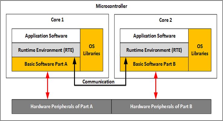
more a functional view, and in reality exchanges with the BSW usually more suited to access the HW peripherals, one is more
are distributed over the complete sequence. But note that there suited to computation, not all may reach the same frequency,
could be a MCC1 case, where only one core, out of all cores have the same performance index. It ends up in a situation
of the controller, can be used by the ASW. This might be an where the best location for the BSW interrupts is core 0
intermediate step in the introduction of multi-core, or even an for one controller, but core 1 for another controller of the
architectural choice, when a high end controller is used for same family. Similarly, safety relevant functions which have
e.g. increased ROM demands rather than computation power. to be executed under the control of a checker core have to be
located on core 0 on one controller, but core 1 on another one.
The consequence of such situation (i.e. diversity of controller
architectures) is a variety of ASW architectures, as the core
allocation of the ASW functions finally might get influenced
by the controller architecture. Therefore, to reduce this effect,
a core abstraction concept as shown before allows to share the
same ASW Architecture (i.e. task system) for different projects
based on different controllers. Abstract cores (SW cores) are
Figure 18. Distribution of a Calculation Sequence on a MCC1 BSW decoupled from real physical cores (HW cores), and a mapping
is established between them.
2) MCC2 - Distributable BSW: The BSW can be Out of the defined MCC one can easily apply the definition
distributed across cores, and the BSW interfaces are available
on all cores. In this case, the ASW components can be
located on any core, reaching to a high level of flexibility:
Typically, an ASW component controlling a PWM does
not need to be integrated on the same core, where the
PWM driver is integrated. Furthermore, two different ASW
components controlling two different valves through PWMs
do not need to be integrated on the same core, although Figure 20. MCC3 BSW with Core Abstraction for free Core Distribution
they are addressing the same driver and the same HW. The
to the AUTOSAR architecture following the listed rules:
• MCC1 is applied to all BSW modules which are intended
for the purpose of raw access to memory devices such as
flash drivers, memory tests etc. So it is required that one
interface level above performs the core abstraction.
Figure 19. MCC2 BSW with Focus on Functional Coupling excluding BSW
• MCC2 is applied to BSW which needs to access HW
driver takes care of the possible conflicts. With such a MCC2 peripherals or core registers and therefore needs to know
BSW, the freedom for ASW runnables integration is high, on which core it is operating such as typical MCAL
and one can concentrate on the pure functional and data flow drivers. Call-outs and interrupts need to be configured
constraints. Of course, the level of freedom one can achieve to the correct physical core.
• MCC3 is applied to BSW which does not access HW
here, depends on the underlying cross core communication
overhead (e.g. buffering, interaction, locking, synchronization, and so does not need to know on which core it is
...) or an acceptable asynchronism. For the majority of cases, integrated to. Call-outs and interrupts are routed to the
like PWM commands, ADC inputs, and many more, this according core defined by the core abstraction set-up of
overhead, or asynchronism is fully acceptable. For some the project.
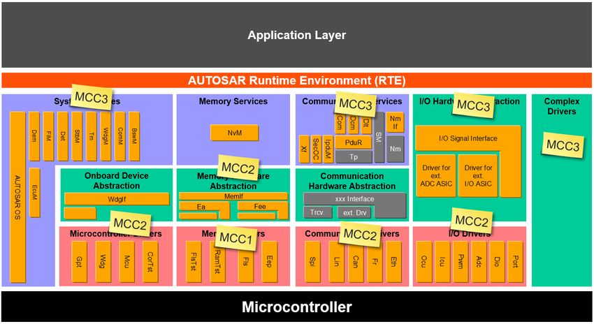
others, not. For the more complex real time functions like
the acquisition of the engine speed (precision required in a Figure Figure 21 shows the assignment of MCC to the
time resolution of a few microseconds), the decoupling is AUTOSAR architecture.
not affordable. For other functions the link to the HW is not
motivated by the real-time constraints, but by the availability D. Achievements with Core Abstraction and MCC
of some HW feature on a given core: such as cores equipped Of course, the shown ideas of core abstraction and multi-
with a double precision floating point unit, cores with core conformance classes (MCC) is standardized in our orga-
lock-step (checker) capability for safety implementations etc. nization, but may be adapted to answer a particular project
request. This approach allows also to handle the diversity
3) MCC3 - Abstracted BSW: The BSW provides an ab- across HW families and controller suppliers. The same prin-
straction of the cores, which eases the handling of diversity ciple applies for all new families, and allows an extension to
between cores, and controllers. For instance, even in the upcoming hardware architectures with 6 or even more cores.
same controller family (e.g. Infineon Aurix), the cores are As an ultimate goal of the core abstraction, it is intended that
not equivalent (not full symmetric architecture): one core is the ASW is more and more integrated according to recurrenceFigure 22. Core Performance of current Projects
Figure 21. AUTOSAR Architecture with assigned MCC
has towards the system it is running on, which are mainly
constraints (see Figure 2) and sequence constraints (see Fig- functionally driven. So it is obvious to introduce so called
ure 17), more and more independently of core considerations. ”Multi-Core Conformance Classes” (MCC) to be assigned to
”Meta”-containers are defined, which contain a chain of tasks BSW modules or stacks what indicates to the ”customers”
executed in sequence and on different cores. In some rare of the BSW what the BSW is able to offer in terms of
cases, core affinities can be specified which may influence multi-core compliance. Such is especially interesting as
the targeted task (core). In this exceptional case, an affinity sometimes 3rd party BSW solutions have to be applied which
versus a specific feature of the core is specified, not to a are - unfortunately - mostly usable on single cores only. So
special core identifier (which may not apply on a different one can easily equip the AUTOSAR architecture with a MCC
controller). For instance, affinity to an active checker core, to tag to describe the needs and multi-core compliance of a
a double precision FPU, etc. may be specified. given platform.
IV. S UMMARY AND O UTLOOK
B. Future Steps
A. Conclusion
Unfortunately today there still exists a restricted vision
Using efficiently multi-core micro-controllers one can not
of what can be done with multi-core micro-controller and
directly apply the AUTOSAR standard to all ASW SWCs and
software architectures. Thus only a few software vendors
BSW modules. This is because the standard does not allow
acting in the domain of Powertrain including the ones offering
a proper distribution of software across cores what would
shared services such as operating systems and communication
decrease the degree of parallelization according to Amdahl’s
solutions provide according multi-core solutions to the market.
law[8]. But to distribute the software one needs first an ASW
Therefore it is highly appreciated that the AUTOSAR consor-
which allows a core distribution by SWC runnable to keep
tium launched a work group in the work package architecture
calculation chains, and second a BSW which is accessible
(WP-A) with the goal to rework the multi-core distribution of
on all cores with an identical interface behaviour. This BSW
BSW (WP-A MCBD) where the concepts of a real multi-core
architecture replaces several synchronous operations by asyn-
implementation shall be brought up to the standard. This shall
chronous ones exactly at the point the core boundary needs
be done by driving the standard introducing the ideas sketched
to be crossed. Doing this the BSW also takes care about
within this paper.
serialization of requests coming from runnable sequences
of different cores which could request concurrent access to R EFERENCES
the BSW. The price for that is to leave the ICC2 interface [1] AUTOSAR. Release 3.0. In http://www.autosar.org.
compliance which then needs to be resolved by a kind of [2] AUTOSAR. Release 4.0.3. In http://www.autosar.org.
interface abstraction if the exact AUTOSAR behaviour is [3] AUTOSAR. Release 4.2.2. In http://www.autosar.org.
[4] AUTOSAR. Release 4.3. In http://www.autosar.org.
demanded by the user software, e.g. in case of 3rd party or [5] AUTOSAR. Specification of memory mapping rev 4.2.2. In
OEM solutions. At the end, both kinds of software can be http://www.autosar.org.
found inside the Powertrain platform of Continental used in [6] Denis Claraz, Franck Grimal, Thierry Ledier, Ralph Mader, and Gerhard
Wirrer. Introducing multi-core at automotive engine systems. In ERTS2,
current products which are already used in series production 2014.
of several OEMs with well balanced ECUs regarding core [7] Denis Claraz, Stefan Kuntz, Ulrich Margull, Michael Niemetz, and
resource consumption according to Figure 22. Gerhard Wirrer. Deterministic Execution Sequence in Component Based
Multi-Contributor Powertrain Control Systems. In ERTSS 2012, 2012.
Besides the final implementation and the performance [8] Wikipedia. Amdahls law. In https://en.wikipedia.org, 2017.
optimal solution it is important to provide an architecture
which is understandable and re-usable. For that purpose
the core abstraction is introduced to stop the thinking in
certain cores but instead understanding the needs a softwareYou can also read