The Finite Element Modelling of a Rectangular Slab Lying on Multilayer Elastic Soil - Atlantis Press
←
→
Page content transcription
If your browser does not render page correctly, please read the page content below
Advances in Engineering Research, volume 210
                        Conference on Broad Exposure to Science and Technology 2021 (BEST 2021)

    The Finite Element Modelling of a Rectangular Slab
              Lying on Multilayer Elastic Soil
                    Soelarso1, Jean-Louis Batoz1*, E Antaluca1, F Lamarque1
1
Laboratoire Avenues Alliance Sorbonne Université-Université de Technologie de Compiègne, France
*
Corresponding author. Email: jean-louis.batoz@utc.fr

ABSTRACT
The present paper deals with the finite element modeling of a simple raft foundation supported by elastic soil in order
to define the best parameters to model more complicated foundation systems in the future taking into accord the soil-
structure interaction. The finite element parameters are the type of elements, the contact conditions (sliding or sticking),
the size of the domain to consider. In order to validate our models, we compare our results with those of Cuira and
Simon, published in 2008 in a Geotechnical Journal. The quantities which are evaluated are the differential settlements,
the distribution of reaction stresses and the stresses in both the raft and the supporting multilayer soil.

Keywords: FEM, Rectangular Slab, Elastic Soil, Raft Foundation

1. INTRODUCTION                                                   2. DESCRIPTION OF THE PROBLEM AND
      The present paper deals with the linear static analy-          RESULTS BY CUIRA AND SIMON
sis of a reinforced concrete raft shallow foundation sup-               In [5], the authors are considering the formulas of
ported by a multilayer soil using the finite element              Steinbrenner/Boussinesq for computing the differential
method. Our objective is to model the structure and sup-          settlements and the slab is modelled by rectangular
porting soil using 3D classical elements The raft as well         Kirchhoff plate bending finite elements with three dof
as the supporting soil will both be assumed as linear elas-       per node. Sliding contact is assumed at the interface slab-
tic continuum solids within the range of loadings they are        soil. The authors [2.2] have developed a dedicated soft-
subjected to [6]. All computations have been performed            ware called TASPLAQ taking into account the coupling
using Altair Hyperworks [9], with Hypermesh for the               between the plate finite elements and the Boussinesq for-
pre-post processing and Optistruct for the solver. We will        mulas. Their approach requires the computations of sev-
mostly favor the use of Hexahedron (brick) H8 elements            eral matrices such as a flexibility matrix relating the local
with limited distortion since this type of element in Op-         interaction pressures and the settlements. The final mod-
tiStruct is highly performing (an extension to 3D of the          ified stiffness matrix to be “inverted” is not symmetric,
Q4WT element proposed by Wilson and Taylor [7]).                  but the method avoids discretization of the soil by 3D fi-
That element is able to model the bending of plates with          nite elements.
two elements though the thickness without shear locking,                A rectangular (RC) slab with dimensions 20 m x 20
however for stress evaluation it is necessary to use more         m and thickness 25 cm is subjected to two concentrated
than two elements through the thickness. Regarding the            loads of 500 kN at two points. The plate rests on soils
modelling of the soil structure interaction, we will con-         with material properties given in figure 1. The plate is
sider two extreme situations, namely sliding contact              meshed by rectangular 2D plate elements. The results on
(zero friction) and sticking contact (or full continuity of       figure 2 are the distribution of reactions along AX and
displacements). Our results will be compared to those re-         the settlements. The maximum values are 45 kPa and 6.6
ported by Cuira and Simon [5].                                    mm. The authors also report the distribution of bending
                                                                  moments Mx and My in kN.m/m along AX with peak
                                                                  values under the two concentrated loads on the slab (at 8
                                                                  and 12 m along x), reaching 120 kN.m/m (figure 3). The
                                                                  authors also reported results using the PLAXIS 3D finite

                          Copyright © 2022 The Authors. Published by Atlantis Press International B.V.
    This is an open access article distributed under the CC BY-NC 4.0 license -http://creativecommons.org/licenses/by-nc/4.0/. 129
Advances in Engineering Research, volume 210

element software which is a reference in geotechnical         3. RESULTS AND DISCUSSION LOADING
problems [13]. The results are summarized in Table 1.            CONTACT BETWEEN SLAB AND SOIL.
                                                                 INFLUENCE OF THE 3D MESH AND OF
 Table 1. Comparison of TASPLAQ and PLAXIS 3D
 results [5]
                                                                 DOMAIN SIZE
     Maximum values           TASPLAQ        PLAXIS
                                               3D                   We propose to compare the results reported in [5]
 Displacement (mm)              6.6            6.6            with results obtained by 3D FE results using the different
                                                              software from Hyperworks. We recall that in [5] only the
 Reaction of the soil (kPa)      45              -
                                                              slab is discretized by rectangular bending elements. In
 Moment (Mx) (kN.m/ml)          108            110            our FE model, 3D H8WT element will be used for both
 Moment (My) (kN.m/ml)          122            118            the slab and the soil underneath. In this section we will
                                                              consider, as in [5], sliding contact between the slab and
                                                              the soil, but two aspects will be discussed: the influence
                                                              of the 3D meshes and the influence of the size of the do-
                                                              main of soil surrounding the plate, since that aspect was
                                                              not necessary in [5]. Regarding the size of the domain,
                                                              we will consider size 20 x 20, 30 x 30 and 40 x 40 (in m)
                                                              in xy. The lowest surface (level -30 m) is constrained
                                                              with w = 0 and we will also study the influence of free or
                                                              symmetry conditions on the four vertical surfaces for the
                                                              domain sizes 20 x 20 and 40 x 40 (in m) (figure 4). We
                                                              have been considering three meshes. N0 (18900 H8) cor-
                                                              responds to the mesh of the plate as used by Cuira and
                                                              Simon [5]. N1 (76 032 H8) and N3 373 248 H8 are finer
                                                              meshes. For N0 we consider only two elements through
Figure 1 Rectangular slab under concentrated loads and        the thickness of the slab, but for the other meshes 8 ele-
resting on a multilayer soil [5]                              ments through the thickness are considered. Figure 4
                                                              shows a 3D view of the N0 mesh for the domain
                                                              20x20x30 (in m).

Figure 2 Displacement and reaction of the soil along
AX [5]
                                                              Figure 4 3D model with mesh N0 and domain size
                                                              20x20x30 (m)

                                                                    When the domain size is larger than 20x 20 (in m),
                                                              there is no contact between the slab and the soil. Results
                                                              are reported in Tables 2 and 3 for the different meshes
                                                              and for different constraints on the four vertical surfac-
                                                              es of the 3D domain. We consider both symmetry con-
                                                              ditions and stress-free conditions (figure 4). The maxi-
                                                              mum displacements are increasing when the meshes are
                                                              refined for both types of constraints (around 12%) and,
Figure 3 Bending moments of the slab along AX [5]             as expected, free external surfaces allow more vertical

                                                                                                                      130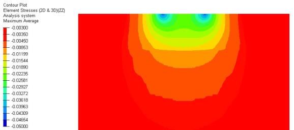
Advances in Engineering Research, volume 210
displacements (around 17%). The effect of the increase (29%), but almost no influence of the domain size and of
of the domain size is to reduce the maximum displace- the stress conditions on the external vertical surfaces.
ments under the loads (by 4% for symmetry conditions This is due to the local character of the stress concentra-
and by 12% when the surfaces are free). tion on the contact surface. This is confirmed on Figure
6 (isovalues of zz on the vertical plane Axz).
Table 2 Vertical displacement. Sliding contact. Do-
main size 20x20x30 m. Table 4 Reaction of the soil (zz stress) sliding con-
Number Maximum Displacement (mm) tact, domain size 20x20 m
Mesh of Ele- Symmetry Free surfaces Maximum Reaction of the soil (kPa)
ments Conditions Mesh Symmetry Condition Free surfaces
N0 18 900 6.77 7.99
N0 35.09 35.16
N1 76 032 6.87 8.08
N1 41.45 41.51
N3 373 248 7.06 8.27
7.06/6.77= (8.27/7.99=1.12) N3 45.25 45.31(45.31/35.16=1.
1.12 (8.27/7.06= 1.17) (45.25/35=1.29) 29)
Table 3 Vertical displacement. Sliding contact. Do- Table 5 Reaction of the soil (zz stress) sliding con-
main size 40x40x30 m tact domain size 40x40 m
Number Maximum Displacement (mm) Maximum Reaction of the soil (kPa)
Mesh of Ele- Symmetry Free surfaces Symmetry Condition Free surfaces
ments Mesh
Conditions N0 35.10 35.10
N0 42 972 6.74 6.98
(6.98/6.74=1.04) N1 41.45 41.46
N1 209 984 6.82 7.07 N3 45.26 45.26
N3 630 843 7.02 7.26
(7.02/7.06= (7.26/8.27=12%
4%) )
(7.26/7.02=1.03)
Figure 6 Iso-values of reaction of the soil. Sliding con-
tact. Mesh N3. Domain size 20x20x30 m. (Zoom in Axz
plane).
Figure 5 Iso-values of vertical displacement. Sliding
contact. N3 mesh with domain size 30x30x30 m.
The isovalues of the w displacement on a central
vertical xz plane are shown on Figure 5 for symmetry
conditions (left) and free surfaces (right) for the fine
mesh N3 and for the 30x30x30 m domain. More dis-
placements are observed in the case of free surfaces (with
u=0.069 mm maximum for the horizontal displacement).
The maximum values of the vertical local reactions
stresses) are reported for the different domains and two
types of conditions on the four vertical planes: for the do- Figure 7 Displacement and reaction of the soil for slid-
main size 20x20x30 see table 4, and for 40x40x30 see ing contact conditions.
table 5. We can notice a significant influence of the mesh
131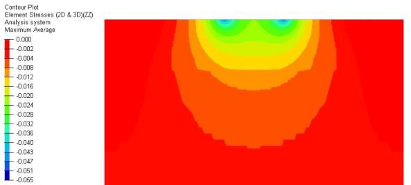
Advances in Engineering Research, volume 210
The distribution of the vertical displacement w and zz Table 7 Bending moments along AX. Sliding con-
stress along AX are given for the domain size of tact. Domain size 40x40 m.
20x20x30 m, for the fine mesh N0 and for symmetry con- Maximum Bending Moments (kN.m/m)
ditions (figure 7) and for the domain size 40x40x30 m, Mesh Symmetry Condition Free surfaces
mesh N3 and free surfaces (figure 8). One can see the
Mx My Mx My
local effects of the two concentrated loads in both figures
and the influence of the mesh, domain size and stress N0 27.43 33.54 27.43 33.54
conditions. N1 70.60 81.49 70.60 81.48
N3 125.56 123.18 125.56 123.18
Figure 8 Displacement and reaction of the soil for slid-
ing contact conditions.
As done in [5] we evaluate the bending moments
Mx and My on the slab, along AX (figure 4), for the two
domain sizes, the two types of boundary conditions on
external surfaces and for the different meshes. The bend-
ing moments Mx and My are related to the stresses xx
and yy . The quality of the results depends on the num-
ber of elements through the thickness but also on the
number of elements on the surface. This can be seen on
tables 6 and 7, when we compare the results using N0 and
N3 for the maximum values of Mx and My along AX. Figure 9 Bending moments Mx and My along AX.
There is a singularity at the positions of the concentrated Sliding contact. Mesh N0 and N3.
loads. However, as for the maximum reaction stresses the
domain size is not important, as well as the conditions on The distribution of Mx and My along AX con-
the outer vertical surfaces. sidering the domain size 20x20 m, the symmetry condi-
tions on the external vertical planes and for mesh N0
Table 6 Bending moments along AX. Sliding con- and N3 are given on Figure 9. One can clearly see the
tact. Domain size 20 x 20 m. strong variations of Mx and My along x, with the peak
Maximum Bending Moments (kN.m/m)) values very sensitive to the mesh. It is also observed
Mesh Symmetry Condition Free surfaces that Mx is changing of sign along x, whereas My re-
mains positive.
Mx My Mx My
N0 27.28 33.43 27.34 33.51 4. RESULTS CONSIDERING STICKING
N1 70.36 81.31 70.45 81.44 CONTACT
N3 125.32 123.01 125.41 123.13 In this section we present the results considering
(125.3/27.3 (123/33.4 sticking contact between the plate and the supporting
=4.6) =3.7) soil. This is equivalent to assuming a full continuity of
the displacements at the soil structure interface. Results
132
Advances in Engineering Research, volume 210
for the maximum displacements are reported in tables 8 presented in the previous section (figure 9) are not sig-
and 9. The influence of the mesh is now limited to 5%, it nificantly changing as seen on Figure14.
was 12% for sliding (section 2), the influence of the
boundary conditions is more important (20% to 5% in the
sliding case). In the average, case per case, the difference
between sticking and sliding contact is a reduction of the
maximum displacement between 5 to 3%.
Table 8. Vertical displacement (sticking contact)
with domain 20 m x 20 m.
Maximum Displacement (mm)
Mesh Number Symmetry Free surfaces
of Ele- Conditions
ments
N0 18 900 6.50 7.78
(7.78/6.50=1.2)
N1 76 032 6.61 7.87
N3 373 6.80 8.06
248 (6.8/6.5=1.05) (8.06/7.78=1.04)
(8.06/6.80=1.185)
Table 9. Vertical displacement (sticking contact)
with domain 40 m x 40 m.
Maximum Displacement (mm)
Mesh Number Symmetry Free surfaces
of Ele- Conditions
ments
N0 42 972 6.41 6.69
(6.69/6.41=1.05)
N1 209 984 6.51 7.79 Figure 10. Iso-values of vertical displacement. Sticking
N3 630 843 6.70 6.98 contact. N3 mesh. Domain size 30x30x30 m (zoom); (a)
(6.7/6.41=1. (6.98/6.69=1.04) Symmetry conditions; (b) free surfaces.
045) (6.98/6.70= 1.04)
Table 10. Reaction of the soil (zz stress). Sticking
The isovalues of the displacements in the verti-cal contact. Domain size 20x20x30 m.
plane Axz are shown in figure 10, for a domain size of Reaction of the soil (kPa)
30x30x30m and for the two types of boundary con-di- Mesh Symmetry Condition Free surfaces
tions on the vertical planes. It is clear that the free condi-
N0 34.72 34.81
tions allow more vertical displacements on the top sur-
face, up to the vertical planes, (with u=0.073 mm maxi- N1 42.38 42.45
mum compared to u=0.68 mm on Figure 5). N3 46.74 46.81
As for the sliding contact, the reactions of the soil
are not influenced by the domain size (Tables 10 and 11)
Table 11. Reaction of the soil (zz stress). Sticking
and by the boundary conditions on the external vertical
contact. Domain size 40x40x30 m.
surfaces. It is also important to see that the values of re-
Reaction of the soil (kPa)
actions are very comparable between sliding and sticking Mesh
contact (only 1 to 3% difference). The peak values of re- Symmetry Conditions Free surfaces
actions are influenced by the number of elements with a N0 34.72 34.73
significant gap between the N0 mesh and the N1 mesh N1 42.38 42.39
(Figures 12 and 13).
We also find that the distribution of bending mo- N3 46.75 46.75
ments is not influenced by the contact conditions be-
tween the slab and the soil (Tables 12 and 13). The results
133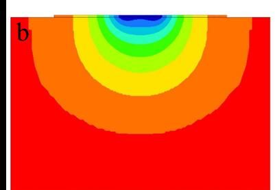
Advances in Engineering Research, volume 210

                                                                 Table 13. Bending Moment of the slab (sticking con-
                                                                 tact) with domain 40 x 40 m
                                                                                   Bending Moment (kN.m/ml)
                                                                 Mesh      Symmetry Condition          Free surfaces
                                                                            Mx           My            Mx          My
                                                                   N0      27.38       33.29         27.34       33.25
                                                                   N1      70.15       80.61         70.11       80.57
Figure 11. Iso-values of reaction of the soil. Sticking            N3     125.08       122.27        125.04      122.23
contact. Mesh N0. Domain size 20x20x30 m. (Zoom in
A xz plane).

Figure 11 shows the isovalues of the reactions of the soil
in the vertical Axz plane (zoom). It is quite similar to fig-
ure 6 (sliding contact).

                                                                Figure 14. Bending moments (Sticking contact) (N0)

                                                                      Addition of CNC to PLA matrix was increase ten-
                                                                sile strength and elongation at break from edible film.
Figure 12. Displacement and reaction of the soil                Mechanical properties of edible films that ap-proached
                                                                the standard edible film were obtained by adding 20%
                                                                CNC to the PLA matrix (T5 100: 20), with tensile
                                                                strength and elongation at break were 7.68 MPa and
                                                                22.4% respectively. Based on the results of func-tional
                                                                group analysis, it appears that the PLA/CNC edi-ble film
                                                                composite has been formed.
                                                                      In this study we have proposed different 3D Finite
                                                                Element models for the analysis of the problem proposed
                                                                by Cuira and Simon [5], using the FE software Altair Hy-
                                                                perworks. Different aspects have been consid-ered: in-
                                                                fluence of the domain sizes, influence of the boundary
                                                                conditions on the external vertical planes, influence of
Figure 13. Displacement and reaction of the soil                the mesh density in the slab and in the soil. We also com-
                                                                pare the results considering sliding contact and sticking
 Table 12. Bending Moment of the slab (sticking con-            contact at the slab soil interface. The re-sults are sum-
 tact) with domain 20 x 20 m                                    marized in tables 14 to 16 for the maxi-mum displace-
                    Bending Moment (kN.m/ml)                    ments, maximum reactions and maxi-mum bending mo-
 Mesh                                                           ments. Our FE results are compared with some values re-
           Symmetry Condition            Free surfaces
                                                                ported in [5] (software TASPLAQ and PLAXIS 3D).
             Mx           My             Mx          My
   N0      27.38         33.21         27.16        33.15
   N1      70.07         80.47         69.88        80.45
   N3      125.00       122.14         124.81      122.11

                                                                                                                         134
Advances in Engineering Research, volume 210
Table 14. Comparison of the maximum displacements
Maximum Displacement (mm)
Domain of soil Sliding Contact Sticking contact TASPLAQ PLAXIS 3D
Symmetry Free surfaces Symmetry Free surfaces
Conditions Conditions
20x20 m
N0 6.77 7.99 6.50 7.78 6.6 6.6
N1 6.87 8.08 6.61 7.87
N3 7.06 8.27 6.80 8.06
40x40 m
N0 6.74 6.98 6.41 6.69
N1 6.82 7.07 6.51 7.79
N3 7.02 7.26 6.70 6.98
Table 15. Comparison of the maximum reactions of the soil.
Maximum Displacement (mm)
Domain of soil Sliding Contact Sticking contact TASPLAQ PLAXIS 3D
Symmetry Free surfaces Symmetry Free surfaces
Conditions Conditions
20x20 m
N0 35.09 35.16 34.72 34.81 45 45
N1 41.45 41.51 42.38 42.45
N3 45.25 45.31 46.74 46.81
40x40 m
N0 35.10 35.10 34.72 34.73
N1 41.45 41.46 42.38 42.39
N3 45.26 45.26 46.75 46.75
Table 16 Comparison of bending moments.
Bending Moments (kN.m/m)
Domain Sliding Contact Sticking contact TASPLAQ PLAXIS 3D
of soil
Symmetry Free surfaces Symmetry Free surfaces
Conditions Conditions
20x20 m Mx My Mx My Mx My Mx My Mx My Mx My
N0 27.28 33.43 27.34 33.51 27.38 33.21 27.16 33.15
N1 70.36 81.31 70.45 81.44 70.07 80.47 69.88 80.45
N3 125.32 123.01 125.41 123.13 125.00 122.14 124.81 122.11 108 122 110 118
40x40 m
N0 27.43 33.54 27.43 33.54 27.38 33.29 27.34 33.25
N1 70.60 81.49 70.60 81.48 70.15 80.61 70.11 80.57
N3 125.56 123.18 125.56 123.18 125.08 122.27 125.04 122.23
135Advances in Engineering Research, volume 210
3D FEM based on linear elasticity can be efficiently 73-82. Jurnal Teknologi (Sciences & Engineering)
used to solve geotechnical problems of shallow founda- Universiti Teknologi Malaysia.
tion systems supported by elastic soils when the maxi- [9] https://www.altair.com/hyperworks/
mum soil compression stress is much smaller (< 1/3) [10] Soelarso , Antaluca E. , Batoz J.L. , Lamarque F.,
compared to the soil ultimate bearing stress capacity On the finite element bearing capacity analysis of a
(also taking into account safety factors). Our results are rib system to be used as shallow foundation con-
in good agreement regarding settlements and structure struction, IOP Conf. Ser.: Mater. Sci. Eng. 673
internal stresses obtained by other numerical models pre- 012030, 2019
sented in [5]. We believe that we can now consider the [11] Soelarso , Antaluca E. , Batoz J.L. , Lamarque F.,
static analysis of SNSF structures in the context of real On the FE modeling of a SNSF shallow foundation
constructions involving an upper structure supported by system in the context of soft soil in Indonesia,
a shallow foundation (raft or SNSF type), as shown in [10 ACEM20 Structures20 Conference, CS220 Session
to 12]. Seoul, 25-28 August 2020.
[12] Soelarso , Antaluca E. , Batoz J.L. , Lamarque F.,
5. CONCLUDING REMARKS On the finite element modeling of a particular shal-
The main conclusions are the FE Models we built low foundation system for soft soil Coupled Sys-
are able to solve the problem with efficiency, precision tems Mechanics, Vol. 10, No. 3 (2021) 247-261.
and versatility to model the soil-structure interaction. In [13] https://www.plaxis.com/
the present situation the sliding contact and the sticking
contact are giving almost the same results for the reac-
tions and for the bending moments but slightly more dis-
placements when considering sliding contact (+ 5 to 3%).
Therefore, sticking contact, or full continuity of displace-
ment, is a satisfactory and simpler approach for simula-
tion in geotechnical problem of soil structure interaction.
Our FEM results are in good agreement with the results
reported in [5] for the maximum displacements, reactions
and bending moments.
REFERENCES
[1] Batoz J.L, Dhatt G. (1990). Modélisation des
structures par éléments finis "solides élastiques",
Vol. 1, Hermés Science Publications, France.
[2] Dhatt G., Touzot G., The finite element displayed, J.
Wiley, 1984.
[3] Bathe K.J., Finite element procedures, Prentice Hall,
1996.
[4] Zienkiewicz, O.C., Taylor, R.L., Zhu, J.Z., The Finite
element method. Its basis and fundamentals, Elsevier,
6th Edition, 2005.
[5] Cuira F, Simon B. (2008). "Modélisation 3D simpli-
fiée d'une plaque sur sol multicouche élastique", Rev-
enue Francaise Geotechnique, No 124, pp 3-17, 2008.
[6] Terzaghi K. “Theoretical soil mechanics -Theory of
Semi-infinite elastic solids, 1943.
[7] Wilson, E.L., Taylor, R., Doherty, S.P., Ghaboussi, J,
(1973), “Incompatible displacement models”, in Fen-
ves et al. (eds), Numerical and Computer Methods in
Structural Mechanics, Academic Press, New York,
pp.43-57,1973.
[8] Darjanto H, Irsyam M, Retno S.R, (2015), “Full Scale
Load Test on The Spider Net System”, 77:11(2015)
136You can also read