UNI MP100 User's Guide - Single-Gas Detectors - mPower Electronics Inc.
←
→
Page content transcription
If your browser does not render page correctly, please read the page content below
UNI
Single-Gas Detectors

     MP100

 User’s Guide

                      Rev. 1.16
                  February 2022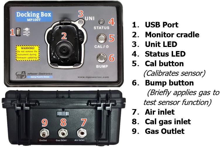
UNI MP100 User’s Guide

                                                          Contents
1.   General Information ................................................................................................................. 3
2.   User Interface ........................................................................................................................... 3
3.   Display ..................................................................................................................................... 4
4.   Operation.................................................................................................................................. 5
     4.1 Turning the Unit On and Off ........................................................................................ 5
     4.2 Warm-up Sequence ....................................................................................................... 5
     4.3 Normal User Mode ....................................................................................................... 5
          4.3.1 Real Time Readings ........................................................................................... 5
          4.3.2 STEL.................................................................................................................. 5
          4.3.3 TWA................................................................................................................... 6
          4.3.4 Peak ................................................................................................................... 6
          4.3.5 Minimum (Oxygen Sensor Only) ...................................................................... 6
          4.3.6 Alarm Log.......................................................................................................... 6
          4.3.7 Backlighting....................................................................................................... 6
     4.4 Configuration Mode ..................................................................................................... 7
          4.4.1 Entering and Exiting Config Mode ................................................................... 7
     4.5 Sensor Calibration and Bump Test ............................................................................... 7
          4.5.1 Zero (Fresh Air) Calibration .............................................................................. 7
          4.5.2 Span Calibration ................................................................................................ 8
          4.5.3 Bump Test .......................................................................................................... 9
     4.6 Setting Instrument Configurations................................................................................ 9
          4.6.1 Alarm Limits...................................................................................................... 9
          4.6.2 Oxygen Monitors ............................................................................................. 10
          4.6.3 Span Value ....................................................................................................... 10
          4.6.4 Bump/Cal Intervals .......................................................................................... 10
          4.6.5 Gas Concentration Unit ................................................................................... 10
          4.6.6 Vibrator Enable/Disable ...................................................................................11
          4.6.7 Power-on Zero Enable/Disable .........................................................................11
          4.6.8 Fast Power-on Enable/Disable..........................................................................11
          4.6.9 Configuration Reset ..........................................................................................11
5.   Computer Interface ................................................................................................................ 12
6.   UNI Docking Box (MP100T) Calibrations............................................................................ 14
     6.1 Docking Box Set-up ................................................................................................... 14
     6.2 Docking Box Gas Connection and Calibration Process ............................................. 15
     6.3 Docking Box Data Download and Calibration Certificates ....................................... 16
7.   Maintenance and Specifications ............................................................................................ 18
     7.1 Battery Replacement................................................................................................... 18
     7.2 Sensor Filter Replacement .......................................................................................... 19
     7.3 Sensor Replacement ................................................................................................... 19
     7.4 Troubleshooting .......................................................................................................... 20
     7.5 Alarm Signal Summary .............................................................................................. 21
     7.6 Sensor Specifications and Default Configurations ..................................................... 23
     7.7 Instrument Specifications ........................................................................................... 24

                                                                     1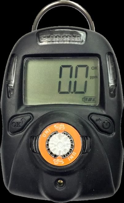
UNI MP100 User’s Guide

                          Read Before Operating
This manual must be carefully read by all individuals who have or will have the responsibility of
using, maintaining or servicing this product. The product will perform as designed only if it is
used, maintained and serviced in accordance with the manufacturer’s instructions.

                                           WARNING !
• Never operate the monitor when the cover is removed.
• Remove the monitor cover and battery only in area known as non-hazardous.
• Use only mPower’s lithium battery part number M500-0001-000 [1.17.02.0002] (3.6V,
  2700mAH, AA size) or part No. ER14505 cell manufactured by EVE Energy Co., LTD
• This instrument has not been tested in an explosive gas/air atmosphere having an oxygen
  concentration greater than 21%.
• Substitution of components will impair suitability for intrinsic safety.
• Substitution of components will void warranty.
• It is recommended to bump test with a known concentration gas to confirm the instrument is
  functioning properly before use.
• Before use, ensure that the colorless ESD layer on the display is not damaged or peeling. (The
  blue protective film used for shipment may be removed.)

                                     AVERTISSEMENT !
• N'utilisez jamais le moniteur lorsque le couvercle est enlevé.
• Retirer le couvercle du moniteur et la batterie uniquement dans une zone connue comme non
  dangereuse.
• Utilisez uniquement la batterie au lithium de mPower, pièce No. M500-0001-000 [1.17.02.0002]
  (3.6V, 2700mAH, taille AA) ou celle de EVE Énergie Cie., Lté, pièce No. ER14505.
• Cet instrument n'a pas été testé dans une atmosphère explosive gaz / air ayant une concentration
  en oxygène supérieure à 21%.
• La substitution de composants compromettra l'aptitude à la sécurité intrinsèque.
• La substitution des composants annulera la garantie.
• Il est recommandé de tester avec un gaz de concentration connu pour confirmer que l'instrument f
  onctionne correctement avant de l'utiliser.
• Avant l'utilisation, assurez-vous que la couche ESD incolore de l'écran n'est pas endommagée
  ou épluchée. (Le film protecteur bleu peut être enlevé.)

         Proper Product Disposal at The End Of Life
                The Waste Electrical and Electronic Equipment (WEEE) directive (2002/96/EC) is
                intended to promote recycling of electronic equipment and their components at end
                of life . This symbol (crossed-out wheeled bin) indicates separate collection of waste
                electrical and electronic equipment in the EU countries. This product may contain
                one or more Nickel-metal hydride (NiMH), Lithium-ion, or Alkaline batteries.
                Specific battery information is given in this user guide. Batteries must be recycled or
                disposed of properly. At the end of its life, this product must undergo separate
                collection and recycling from general or household waste. Please use the return and
                collection system available in your country for the disposal of this product.

                                                2
UNI MP100 User’s Guide

1. General Information
The UNI (MP100) is a single sensor, portable, personal toxic gas monitor. It displays gas
concentration continuously on a big segment LCD. It also monitors the STEL, TWA, Peak and
Minimum (for O2 only) values, and these can be displayed on demand. High, Low, STEL and
TWA alarm thresholds are configurable. The shell is made of high strength, durable material. The
two-key operation is simple to use. Sensor and battery can be replaced easily. Calibration is also
very convenient.

2. User Interface
1.   Audible Alarm Port
2.   LED alarm window
3.   LCD
4.   Left Key (Confirm/Number increasing)
5.   Right Key (Power On-Off/ Cursor moving)
6.   Alligator clip
7.   Sensor Gas Inlet
8.   Vibrator

                                              3
UNI MP100 User’s Guide

3. Display
1.   Gas name, includes: CO, H2S, or O2
2.   Question mark (to confirm action)
3.   Unit status indicator “OK” and to confirm entry
4.   Gas unit, includes: x10-6, ppm, %, mg/m3, µmol/mol
5.   Battery charge status
6.   HIGH, LOW, STEL, TWA alarm indicator (when flashing)
7.   Span calibration (in process or due)
8.   Zero calibration (in process or due)
9.   Concentration reading or other parameter

                                          4
UNI MP100 User’s Guide

4. Operation
4.1 Turning the Unit On and Off
Press and hold the Right Key for 3 seconds, until the red light, buzzer, and vibrator all trigger,
followed by the green light, and the LCD displays “On”. To turn off, press and hold the Right
Key from normal display mode for a 5-second count-down, until the unit displays “Off”.

4.2 Warm-up Sequence
After powering on, the unit enters a warm up and self-test sequence, shows the firmware version

as follows:

   •   If the sensor cannot be identified or is not installed, the screen alternately displays

       and         .

   •   If the Bump or Cal Due setting is enabled and the due date has passed, the display will

       alternate between            or          and          . The Left Key must be pressed to
       acknowledge, otherwise the instrument will turn itself off automatically after 15s.
Lastly, the following values will be shown accordingly:
   • High alarm threshold
   • Low alarm threshold
   • STEL (short-term exposure limit) alarm threshold
   • TWA (8-hour time-weighted average) alarm threshold
4.3 Normal User Mode
4.3.1 Real Time Readings
When warm-up is complete, the unit enters normal mode and starts displaying
instantaneous gas concentrations.

By pressing the Right Key the user can check other values including STEL,TWA, PEAK, MIN
(for O2 only) and Alarm Log. The display returns to real time readings from any other screen if
there is no key action for 60 seconds.
4.3.2 STEL
This displays the Short Term Exposure Limit (STEL) calculation, which is the
average concentration in a moving window over the previous 15 minutes. The

                                                5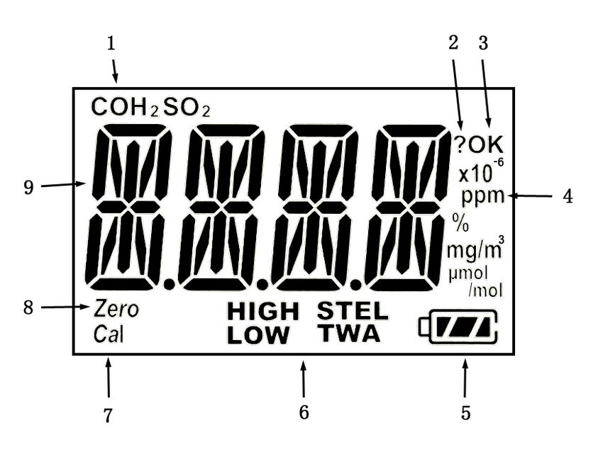
UNI MP100 User’s Guide

STEL value rises and falls with some lag time over the instantaneous reading.
A STEL alarm cannot be cleared except by turning the unit off and back on,
but will clear automatically after 15 minutes in clean air.
4.3.3 TWA
This displays the Time-Weighted Average (TWA) calculation, which is the
average concentration times the fraction of 8 hours that the instrument has
been on. The TWA value is similar to a dose in that it rises but never falls,
until it is reset by turning the unit off. Likewise, a TWA alarm cannot be
cleared except by turning the unit off and back on.
4.3.4 Peak
The Peak screen shows the highest value since the unit was
turned on.

Press the Left Key to enter the Clear Peak screen and Press
the Left Key again to acknowledge and clear the Peak value.

4.3.5 Minimum (Oxygen Sensor Only)
The Minimum screen is used for the oxygen sensor only
and shows the lowest value since the unit was turned on.

Press the Left Key to enter the Clear Min screen and Press
the Left Key again to acknowledge and clear the Min value.
4.3.6 Alarm Log
Up to 50 alarm events lasting ≥5 seconds are logged into
memory and the last 10 such events can be viewed on the
instrument. When A 1 is reached using the Right Key, it
flashes between the A 1 screen and a screen showing the
alarm concentration and type. Values preceded by a “--” with no alarm label indicate a negative
concentration alarm event. Use the Left Key to cycle through the 10 available alarms. To view all
50 alarm events along with date and time stamps, it is necessary to use a Docking Box or
CaliCase connected to a computer with mPower Suite software.
4.3.7 Backlighting
Holding down the Left Key for a few seconds causes the red alarm LEDs to stay on for 5
seconds. This helps the user read the display when in darkness.

                                              6
UNI MP100 User’s Guide

4.4 Configuration Mode
In Config mode, the user can change parameters and calibrate the unit. In general, use the Left
Key to increase the number or confirm an operation, and use the Right Key to move the cursor or
go to the next menu item.
4.4.1 Entering and Exiting Config Mode
Press and hold the Left Key and the Right Key together for 3 seconds until the password screen

is displayed,       followed by        , with one digit or cursor flashing, to prompt the user to
enter the password. The default password is 0000. Use the Left Key to increase the number, and
the Right Key to move the cursor, and the Left “OK” Key again to accept the password input and
enter Config mode. If the digit input is incorrect, use the Right Key to move the cursor and Left
Key to change the input.
NOTE: The MP100 default password is 0000.

To exit Config Mode, press the Right Key until          is displayed, and acknowledge with the
Left Key to return to Normal Mode. Alternatively, just wait for one minute and the unit will
automatically revert to Normal Mode.

4.5 Sensor Calibration and Bump Test
Before the unit can monitor gas correctly, it needs to be calibrated using zero and span gas.
Calibration and Bump Tests are recorded in the instrument datalog for compliance purposes.
4.5.1 Zero (Fresh Air) Calibration
Zero calibration sets the baseline for the sensor. It is preferably done in fresh air at the same
ambient temperature and humidity as will be used for measurements. However, nitrogen, dry
cylinder air, or other gas source known to be free of detectable compounds can also be used. One
exception is that for an oxygen (O2) sensor the Fresh Air Calibration sets the value to 20.9%, so
air must be used.

From the         menu, press the Left Key to start a zero calibration. The unit displays a 15-

second count-down followed by the calibration result as either         or        . The user can

abort the zero calibration during the count-down by pressing the Right Key, after which
is displayed.

                                              7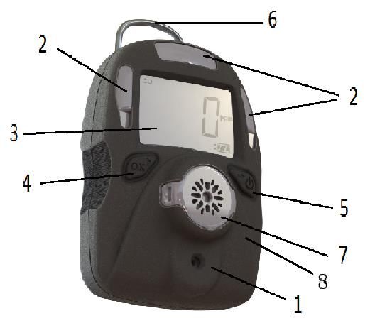
UNI MP100 User’s Guide

4.5.2 Span Calibration
Span calibration determines the sensitivity of the sensor to the gas. Recommended calibration
gases and concentrations are listed in Section 7.6 at the end of this manual and in TA Note 4
(available at www.mpowerinc.com). Special calibration procedures for highly reactive gases are
described in TA Note 6. Oxygen sensor calibration is reversed from other sensors and uses pure
nitrogen with 0% oxygen during the span procedure and 20.9% oxygen (air) during the fresh air
“zero” procedure. We recommend using a fixed flow regulator of at least 0.3 LPM but no more
than 0.6 LPM. Use as short tubing connections as possible.
Span Calibration Procedure
1. Connect the Calibration Adapter to the span gas cylinder’s regulator and snap it into place
   over the UNI sensor.

2. Enter the         menu, start the gas flow, and press the Left Key to start the calibration
   count-down. The calibration time is typically 60 seconds but may be shorter or longer
   depending on the sensor type.

3. To abort the span calibration during count-down, press the Right Key and       is displayed.

4. After count-down, the span calibration result       or        is displayed.
5. Turn off the gas supply and remove the Calibration Adapter.

                                           CAUTION
  During normal monitoring, never operate the MP100 with the Calibration Adaptor attached
  because it will block diffusion of gas into the sensor.

                                              8
UNI MP100 User’s Guide

4.5.3 Bump Test
A Bump Test is a quick check to ensure that the sensor and alarms are working properly. It is

done with the same gas as is used for span calibration. Enter the          menu, start the gas flow,
then press the Left Key to start bump count-down (typically 45 seconds, but varies with sensor).

After count-down, the bump test result          or         is displayed.

To abort the bump test during count-down, press the Right Key and             is displayed.

Although a Bump Test is a recorded event in the datalog, the user can always do an unrecorded
bump check such as by breathing into an oxygen monitor just to verify that the sensor and alarms
are functioning.

4.6 Setting Instrument Configurations
4.6.1 Alarm Limits
 MP100 toxic gas monitors alarm with 2 beeps & flashes per second when concentrations are
over the Low Alarm setpoint, and 3 beeps & flashes per second when over the High Alarm
setpoint. See Section 7.5 for a summary of alarm signals and Section 4.6.2 for Oxygen Monitor
alarms.
All the preset alarm limits, HIGH, LOW, STEL & TWA can be changed. From these menus

                 ,                 ,                 , and              , press the Left Key to
change the corresponding alarm limit, using the same process as for entering a password (Section
4.4.1):
The current setting value is displayed, with the first digit flashing:

Use the Left Key to increase the current digit, cycling from 0 to 9:

Use the Right Key to move the cursor to the next digit:

After all digits are entered, use the Right Key to move to the “OK” symbol,
and press the Left Key to save the entry. The unit will display SAVE for a
few seconds while storing the value; it is not necessary to press OK to
initiate saving.

                                               9
UNI MP100 User’s Guide
Silence Mode can be entered using mPower Suite (Section 5). In this mode, the audio alarm is
disabled when exceeding the Low Alarm, with no change to the visual and vibration alarms. The
audio alarm is still enabled when exceeding High, STEL, TWA or Overrange Alarm conditions.
NOTE 1: The MP100 will show an error message “Err” if:
• The Low alarm is attempted to be set higher than the high alarm setting.
• The High alarm is attempted to be set lower than the low alarm setting.
• The entered value is outside the measuring range.
4.6.2 Oxygen Monitors
Standard Oxygen Monitors: Oxygen monitor alarms function differently than toxic gas
montior alarms in that the normal ambient air reading is 20.9% and an alarm is triggered when
the reading goes BELOW the Low alarm setpoint or ABOVE the High Alarm setpoint. Oxygen
monitors do not have STEL or TWA alarms.
Inert Oxygen Monitors: Oxygen monitors programmed for inert gas applications do not alarm
when the O2 concentrations are below the Low Alarm setpoint or above 19.5%. They give a Low
Alarm (2 beeps/sec) when between the Low and High Alarm setpoints and a High Alarm (3
beeps/sec) when between the High Alarm setpoint and 19.5%. The default Low and High alarm
setpoints are 4% and 5%, respectively, but can be adjusted, while the 19.5% limit is fixed. Thus,
this version is useful both for oxygen deficiency monitoring in normal ambient air when users do
not wear a breathing apparatus, and in inert gas environments, where breathing apparati are
required, to warn of high oxygen levels that may allow explosion to occur.
4.6.3 Span Value
The span gas concentration can be changed from the Cal SET menu using
the same process as for setting alarm limits.
NOTE: The MP100 will show an error message “Err” if:
• The Span setting is less than 5% of the measuring range or greater than the measuring range.
• For the Oxygen sensor, the span setting is greater than 19.0%.
4.6.4 Bump/Cal Intervals
In the Bump and Cal Interval menus, the LCD alternates between: and , or
and . Press the Left Key to enter the menu and change the interval using the same process
as for setting alarm limits. Note that a value of 0 means Bump or Cal notifications are turned off.
NOTE: The MP100 will show “Err” if the interval is out of the valid range: 0-180 day(s).
4.6.5 Gas Concentration Unit
The gas concentration unit menu alternates between and . Press the Left Key to enter the
gas unit sub-menu, showing the currently selected unit blinking. Unit options include x10-6, ppm,
mg/m3 and µmol/mol for toxic gas sensors, and % for oxygen. Use the Right Key to scroll
through the unit list and select, and the Left Key to confirm and exit.
10UNI MP100 User’s Guide
4.6.6 Vibrator Enable/Disable
The vibrator consumes a lot of power and can be disabled to extend the battery life. The Vibrator
menu alternates between and . Press the Left Key to change the vibrator
enable/disable status. The current vibrator status is displayed, alternating between and
if enabled, or between and , if disabled. Use the Right Key to change the
status, and use the Left Key to confirm and exit.
4.6.7 Power-on Zero Enable/Disable
The sensor baseline may shift due to changes in environment conditions, such as temperature or
humidity, and require a zero calibration. The MP100 can prompt the user to zero calibrate every
time the unit is powered on, and this feature can be enabled/disabled.
The Power-on Zero menu alternates between and . Press the Left Key to change
the power-on zero enable/disable status. The current status is displayed, alternating between
and if enabled, or between and if disabled. Use the Right Key to
change the status, and the Left Key to confirm and exit. When the unit is re-started and user is
prompted with to zero, it must be initiated within 30 s or else the zeroing is skipped.
4.6.8 Fast Power-on Enable/Disable
If fast startup is enabled, the screens showing HIGH/LOW/STEL/TWA alarm threshold values
will be skipped during warm up sequence. On start-up, the unit shows the firmware version
number and then goes directly to concentration readings.
The fast power-on menu alternates between and . Press the Left Key to change the
fast startup enable/disable status. Enable or disable Fast Power-on and confirm the status using
the same process as for Vibration Alarm or Power-on Zero enable/disable.
4.6.9 Configuration Reset
If some unit parameters are incorrect and the user has difficulty correcting them, this menu can
be used to set the all the configuration parameters back to the factory default condition. From the
alternating and display, press the Left Key to enter the (reset) menu. Then
press the Left Key to confirm or the Right Key to abort the reset.
11UNI MP100 User’s Guide
5. Computer Interface
Computer interface requires a Single Docking Box or CaliCase Docking Station connected to a
PC fitted with mPower Suite software. mPower Suite can be used to 1) download logged alarm
and calibration events, 2) upload configuration parameters to the instrument and 3) upgrade the
instrument firmware. mPower Suite and instrument firmware can be downloaded from the
website at https://www.mpowerinc.com/software-downloads/ .
1. Connect the USB cable to both the Docking Box and the PC.
WARNING! Connect only in non-hazardous environments!
2. Turn on the instrument and insert it face down into the Docking Box.
3. Start mPower Suite on the PC and click the “Search” button on the bottom panel.
4. Find the instrument in the left bar Device Connected list. Click on the S/N to get the
configuration file from the instrument.
5. Edit the configuration parameters as desired and click “Write” to upload the configuration to
the instrument.
6. “Read” downloads the current configuration file from the instrument.
7. “Save” stores the current configuration file to the PC.
8. “Load” calls up a stored configuration file from the PC to mPower Suite.
9. To update the instrument firmware, select “Firmware Upgrade”. The firmware must first be
downloaded to the PC from the mPower website www.mPowerinc.com.
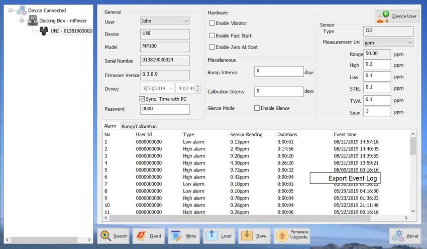
mPower Suite Screen
12UNI MP100 User’s Guide
10. Alarm Events are shown in the bottom half panel and Bump/Calibrations times can be
viewed by clicking on the corresponding tab.
11. To export data to a csv file readable by Excel or other spreadsheet software, move the cursor
over the bottom data panel, right-click the mouse, and then select “Export Event Log”.
Bump/Calibration Results Recalled from UNI Instrument
13UNI MP100 User’s Guide
6. UNI Docking Box (MP100T) Calibrations
6.1 Docking Box Set-up
Before the Docking Box can be used for calibrations, it must be set up for the desired gas type
and span concentration.
1. Connect the USB cable to both the Docking Box and the PC.
WARNING! Connect only in non-hazardous environments!
2. Start mPower Suite on the PC and click the “Search” button on the bottom panel.
3. Find the Docking Box in the left panel Device Connected list and click on it to get the
Docking Box configuration page.
4. Select the Gas Name from the pull-down menu and edit the cylinder gas concentration, lot
number and expiration date as needed.
5. Click “Write” to upload the configuration to the Docking Box. As a reminder, attach a label
to the front panel indicating the gas type. Labels for CO and H2S are provided.
6. The Docking Box will not allow calibrations or bump tests after the cylinder expiration date
entered.
7. Hibernate Timeout is the number of seconds of inaction before the Docking Box turns itself
off automatically. Press the Cal/ button to turn back on.
8. “Save” stores the current Docking Box configuration file to the PC.
9. “Load” calls up a stored Docking Box configuration file from the PC to mPower Suite.
10. To update the Docking Box firmware, select “Firmware Upgrade”. The MP100T firmware
must first be downloaded to the PC from the mPower website www.mPowerinc.com.
14UNI MP100 User’s Guide
6.2 Docking Box Gas Connection and Calibration Process
1. Connect gas and regulator to the quick-connect in the Cal gas inlet port of the Docking Box
using 6-mm or ¼-inch o.d. tubing
2. If ambient air is not free of detectable compounds, connect the air inlet to a fresh air source.
3. If desired, connect tubing to the gas outlet to exhaust away from the operator breathing area.
Docking Box Components Calibration Gas Connections
4. Place the UNI instrument face-down into the cradle.
5. If the Status LED [4] is off, press Cal/ [5] until the LED turns green.
6. Push Cal [5] to initiate calibration or Bump [6] to run a bump test. The LED should blink
green for about 100 s during calibration or 25 s during a bump test.
7. If the calibration or bump is successful, the Unit LED [3] will be green, otherwise red.
8. Up to 2000 Cal or Bump reports will be saved in the internal storage of the Docking Box.
9. To power off, hold the Cal button until the status LED turns off.
Summary of Visual and Audio Alarm Indications
LED Color Buzzer Description
Green blinking None Cal/bump testing
Unit LED Green Beep Once Cal/bump test pass
[3] Orange None Sensor type mismatch
Red 3 beeps per sec Cal/bump test fail
Green None Power On
Status LED
Green blinking None Low battery
[4]
Orange None Charging
Red blinking None Pump block
15UNI MP100 User’s Guide
6.3 Docking Box Data Download and Calibration Certificates
1. To download Cal/Bump test reports, click the Download Log button on the bottom panel. It
is not necessary to have a UNI in the Docking Box. View the reports under the Datalog tab.
Bump/Calibration Results Recalled from UNI Docking Box
2. To export data to a csv file readable by Excel or other spreadsheet software, move the cursor
over the right data panel and click the right mouse button, and then select either the current
Cal/Bump result (Single Datalog) or all the stored results (Whole Datalog).
3. To print a Calibration Certificate, right-click the mouse in the right panel and select Generate
Certificate. Enter any desired information such as operator name and cylinder lot number,
and click Print at the bottom.
16UNI MP100 User’s Guide
17UNI MP100 User’s Guide
7. Maintenance and Specifications
CAUTION!
Maintenance should be performed only by a qualified person who has proper training and fully
understands the contents of the manual.
7.1 Battery Replacement
The battery typically lasts 3 years, but may be drained faster if the unit has
frequently gone into alarm. When the charge is low, the unit displays a red
battery icon and a battery low alarm is triggered once per minute. When the
battery is dead, is displayed and the battery dead alarm triggers
every second. The battery needs to be replaced, as follows:
1) Turn off the MP100 and place it face down on a soft surface.
2) Use a T10 Torx screwdriver to loosen each of the four screws by turning them
counterclockwise.
3) Remove the top cover after carefully unplugging the buzzer connector.
4) Slide the battery out of its compartment.
5) Place the new battery into the compartment with its “+” end oriented toward the “+” on the
printed circuit board.
6) Plug in the buzzer connector and reinstall the top cover.
7) Re-install the screws through the back cover. Be careful to not overtighten the screws.
Filter
Sensor
Battery
18UNI MP100 User’s Guide
WARNING !
• Never operate the monitor when the cover is removed.
• Remove the monitor cover and battery only in area known as non-hazardous.
• Use only mPower’s lithium battery part number M500-0001-000 [1.17.02.0002] (3.6V,
2700mAH, AA size) or part No. ER14505 cell manufactured by EVE Energy Co., LTD.
AVERTISSEMENT !
• N'utilisez jamais le moniteur lorsque le couvercle est enlevé.
• Retirer le couvercle du moniteur et la batterie uniquement dans une zone connue comme non
dangereuse.
• Utilisez uniquement la batterie au lithium de mPower, pièce No. M500-0001-000 [1.17.02.0002]
(3.6V, 2700mAH, taille AA) ou celle de EVE Énergie Cie., Lté, pièce No. ER14505.
7.2 Sensor Filter Replacement
A “peel-and-stick” filter should be used on the MP100 in order to keep debris from fouling the
sensor. Replace the filter whenever it appears dirty, is clogged with particles, has contacted liquid,
or when sensor response becomes weak and/or slow. Use external clip-on filters when operating
in dusty environments for easier filter exchange.
1) Turn off the MP100 and remove the top cover as described above for
battery replacement.
2) Peel off the old filter, and gently press a new filter onto the sensor.
3) Reconnect the buzzer and reinstall the top cover as described above for
battery replacement. Be careful to not overtighten the screws.
7.3 Sensor Replacement External Filter Clip
MP100 models are designed for easy sensor replacement. CO and H2S sensors have typical
operating lives of 5 years, while others are 1 to 2 years, as per warranty (See Specifications in
Section 7.8).
1) Turn off the MP100 and remove the top cover as described above for battery replacement.
2) Replace the old sensor with a new one. Make sure the pins are not bent or corroded. Align the
pins to the corresponding holes and push the sensor straight in. The sensor should fit flush
against the printed circuit board.
3) Check the instrument filter and, if needed, replace as described in the previous section.
4) Reconnect the buzzer and reinstall the top cover as described above for battery replacement.
Be careful to not overtighten the screws.
CAUTION!
Sensors are not interchangeable. Use only mPower sensors, and use only the sensor type
specified for your MP100 monitor. Use of non-mPower components will void the warranty and
can compromise the safe performance of this product.
19UNI MP100 User’s Guide
7.4 Troubleshooting
Problem Possible Reason Solution
Cannot turn on unit Battery not installed Install battery.
Depleted or defective battery. Replace battery.
After turn on unit Calibration due date passed Use Left key to access calibration menu
shows “Cal Due” and and perform calibration. Or use mPower
shuts off with Right key Suite to update to later Cal Due date.
Reading abnormally Incorrect calibration or zeroed when Zero and Span calibrate. Ensure clean air
low detectable gas is present. when zeroing.
(or Fails Calibration) Calibration gas flow > 0.6 LPM Use flow between 0.3 and 0.6 LPM
On-board filter plugged. Replace filter. Use external filter clip in
dusty environments.
Weak sensor. Have Service Technician check raw
counts and replace sensor as needed.
Calibration Adapter is attached. Remove Calibration Adapter.
Reading abnormally Incorrect calibration or degraded Zero and Span calibrate instrument.
high span gas used or tubing absorbs span Ensure span gas is not expired.
(or Fails Calibration) gas Used short, inert (PTFE) tubing
Calibration gas flow < 0.3 LPM Use flow between 0.3 and 0.6 LPM
Environment contains cross- Check TA Note 4 for possible cross-
sensitive substances sensitivities.
Reading abnormally Incorrect calibration or degraded Zero and Span calibrate instrument.
noisy span gas used or tubing absorbs span Ensure span gas is not expired.
(or Fails Calibration) gas Used short, inert (PTFE) tubing
Weak sensor. Have Service Technician check raw
counts and replace sensor as needed.
Buzzer, LED, or Bad buzzer, LEDs, or vibration Call authorized service center.
vibration alarm alarm.
inoperative Blocked alarm port Unblock alarm port.
20UNI MP100 User’s Guide
7.5 Alarm Signal Summary
Display Reason
Over Range alarm:
Buzzer 3 beeps per second
LED 3 flashes per second
1 Vibration per second
“OVER” and “500” (“sensor range”) 1 flash
per second
High alarm:
Buzzer 3 beeps per second
LED 3 flashes per second
1 Vibration per second
“HIGH” 2 flashes per second
Low alarm:
Buzzer 2 beeps per second
LED 2 flashes per second
1 Vibration per second
“LOW” 2 flashes per second
STEL alarm:
Buzzer 1 beeps per second
LED 1 flash per second
1 Vibration per second
“STEL” 2 flashes per second
TWA alarm:
Buzzer 1 beep per second
LED 1 flash per second
1 Vibration per second
“TWA” 2 flashes per second
Negative Drift alarm:
Buzzer 1 beep per second
LED 1 flash per second
1 Vibration per second
21UNI MP100 User’s Guide
Bump Overdue alarm:
Buzzer 1 beep per minute
LED 1 flash per minute
1 Vibration per minute
Cal Overdue alarm:
Buzzer 1 beep per minute
LED 1 flash per minute
1 Vibration per minute
Battery Low alarm:
Buzzer 1 beep per second
LED 1 flash per second
“bAT LoW”1 flash per second
Battery Empty alarm:
Buzzer 1 beep per minute
LED 1 flash per minute
1 Vibration per minute
1 flash per minute
Sensor Error alarm:
Buzzer 1 beep per second
LED 1 flash per second
“SEN Err”1 flash per second
22UNI MP100 User’s Guide
7.6 Sensor Specifications and Default Configurations
Sensor Range Resolution Span* Low High STEL TWA Panel Response Calibration
(ppm) (ppm) (ppm) (ppm) (ppm) (ppm) (ppm) Ring Time t90 (s) Interval†
0-500 1 100 35 200 100 35 15 3 mo
CO
0-1000 1 100 35 200 100 35 15 3 mo
0-1999 1 100 35 200 100 35 15 3 mo
0-50 0.1 25 10 20 15 10 15 3 mo
H2S 0-100 0.1 25 10 20 15 10 15 3 mo
0-200 0.1 25 10 20 15 10 15 3 mo
0-1000 1 25 10 20 15 10 30 3 mo
NH3 0-100 1 50 25 50 35 25 150 1 mo
0-500 1 50 25 50 35 25 150 1 mo
Cl2 0-50 0.1 10 2 5 1 0.5 30 1 mo
ClO2 0-1 0.01 0.5** 0.2 0.5 0.3 0.1 120 1 mo
COCl2 0-1 0.01 0.5** 0.2 0.5 0.3 0.1 120 1 mo
0-1000 1 100 100 400 400 100 70 1 mo
H2
0-2000 1 100 100 400 400 100 70 1 mo
HCN 0-100 0.1 10 4.7 5 4.7 4.7 200 3 mo
NO 0-250 1 25 25 50 25 25 30 1 mo
NO2 0-20 0.1 5 1 10 1 1 30 1 mo
PH3 0-20 0.01 5 1 2 1 0.3 60 1 mo
SO2 0-20 0.1 5 2 10 5 2 15 3 mo
ETO 0-100 0.1 10 2 5 2 1 120 1 mo
(Ethylene Ox) 0-200 0.1 10 2 5 2 1 120 1 mo
O3 0-5 0.01 0.5** 0.1 0.2 0.1 0.1 60 1 mo
HF 0-20 0.1 6** 2 6 6 3 90 1 mo
HCl 0-15 0.1 10** 2 5 5 1 90 1 mo
CH3SH 0-10 0.1 5 2 5 2 0.5 20 3 mo
Acetaldehyde 0-20 0.1 5 2 5 2 1 120 1 mo
THT 0-40 0.1 10 5 10 5 5 60 1 mo
AsH3 0-1 0.01 0.8** 0.2 0.5 0.3 0.1 30 1 mo
* The default span setting equals the recommended span gas concentration.
** Calibration of these sensors requires a gas generator or other special precautions. See TA Note 6 for
recommended procedures and gas sources.
† Suggested calibration interval. Actual required interval must be defined by user and may be shorter under harsh
conditions or longer under favorable conditions – see TA Note 3 for details.
Sensor Range Resolution Span* Low† High† STEL TWA Panel Response
(%) (%) (%) (%) (%) (%) (%) Ring Time t90 (s)
O2 (Galvanic or 0 - 25 0.1 0.0 19.5 23.5 - - Dark 15
Lead-Free) 0 - 30 0.1 0.0 19.5 23.5 - - Blue 15
O2 Inert Alarms† 0 - 30 0.1 0.0 4.0 5.0 - - 15
* Oxygen sensors in MP100 use pure nitrogen or other inert gas for both Span and Bump Test.
† Standard O2 alarms are triggered when O2 levels go either below the Low Alarm or above the High alarm. Inert
monitor alarms are off below the Low alarm or above 19.5% and on above Low & High alarms but below 19.5%.
23UNI MP100 User’s Guide
7.7 Instrument Specifications
Size 3.46 x 2.44 x 1.3 in
(88 x 62 x 33 mm)
Weight 4.4 oz (125 g)
Sensors Electrochemical
Response time 15 seconds (CO/H2S/O2)
(t90) Others vary, see individual sensor specification sheet
Battery Replaceable AA size Lithium battery, 3 years typical operation
Temperature -4°F to 122°F (-20°C to 50°C)
Humidity 5 to 95% relative humidity
(non-condensing)
Alarm Type • High, Low, STEL & TWA alarms adjustable
• Over range alarm
• Low battery alarm
Alarm Signal • 95 dB @ 30 cm
• Bright red LEDs
• Built in vibrator
Calibration 2-point calibration, zero and span, power on zero (user-selectable)
Event Log Up to 50 alarm events
IP Rating IP-67
EMI/RFI EMC directive: 2014/30/EU
Safety Class I, Div 1, Group ABCD
Certifications Class II, Div 1, Group EFG
Class III, Div 1
T4, -20°C ≤ Tamb ≤ +50°C
IECEx Ex ia IIC T4 Ga
ATEX II 1G
Ex ia IIC T4 Ga
Sensor Life CO & H2S expected operating life 5 years or longer, others 1 to 2 years as
per warranty
Warranty 2 years on O2, CO, H2S, SO2, HCN, NO, NO2, and PH3 units including
sensor; 1 year on others
24UNI MP100 User’s Guide
Technical Support and mPower Contacts
mPower Electronics Inc.
3046 Scott Blvd. Santa Clara, CA 95054
Phone: (408) 320-1266
Fax: (669) 342-7077
info@mpowerinc.com
www.mpowerinc.com
25You can also read