User Manual Installation Industrial Ethernet Rail Switch SPIDER Premium Line - Installation SPIDER-PL
←
→
Page content transcription
If your browser does not render page correctly, please read the page content below
User Manual
Installation
Industrial Ethernet Rail Switch
SPIDER Premium Line

Installation SPIDER-PL                          Technical support
Release 10 04/2021                https://hirschmann-support.belden.com
The naming of copyrighted trademarks in this manual, even when not specially indicated, should
not be taken to mean that these names may be considered as free in the sense of the trademark
and tradename protection law and hence that they may be freely used by anyone.

© 2021 Hirschmann Automation and Control GmbH

Manuals and software are protected by copyright. All rights reserved. The copying, reproduction,
translation, conversion into any electronic medium or machine scannable form is not permitted,
either in whole or in part. An exception is the preparation of a backup copy of the software for
your own use.

The performance features described here are binding only if they have been expressly agreed
when the contract was made. This document was produced by Hirschmann Automation and
Control GmbH according to the best of the company's knowledge. Hirschmann reserves the right
to change the contents of this document without prior notice. Hirschmann can give no guarantee
in respect of the correctness or accuracy of the information in this document.

Hirschmann can accept no responsibility for damages, resulting from the use of the network
components or the associated operating software. In addition, we refer to the conditions of use
specified in the license contract.

You can get the latest version of this manual on the Internet at the Hirschmann product site
(www.hirschmann.com).

Hirschmann Automation and Control GmbH
Stuttgarter Str. 45-51
72654 Neckartenzlingen
Germany

                                                                        Installation SPIDER-PL
2021-04-23                                                                      Release 10 04/2021
Contents
Important information 5
Safety instructions 7
About this Manual 15
Key 16
1 Description 17
1.1 General device description 17
1.2 Device name and product code 18
1.3 Device view 20
1.3.1 Front view 20
1.4 Power supply 23
1.4.1 Supply voltage with the characteristic value HH 23
1.4.2 Supply voltage with characteristic value HK 23
1.5 Ethernet ports 23
1.5.1 Pin assignments 25
1.6 Display elements 26
1.6.1 Device state 26
1.6.2 Port status 27
2 Configuration interface 28
2.1 USB interface 28
3 Signal contact 29
4 Installation 30
4.1 Checking the package contents 30
4.2 Mounting the device 31
4.2.1 Installing the device onto the DIN rail 31
4.2.2 Mounting on a flat surface 33
4.3 Grounding the device 34
4.4 Installing an SFP transceiver (optional) 354.5 Connecting the terminal block 36
4.5.1 Connecting the 6-pin terminal block (device variants
with characteristic value HH) 37
4.5.2 Connecting the 6-pin voltage terminal with spring
(device variants with characteristic value HK) 39
4.6 Operating the device 41
4.6.1 Installing terminal blocks, switching on the supply
voltage 41
4.6.2 Connecting data cables 41
5 Configuration (optional) 42
5.1 Configuration readout 47
6 Monitoring the ambient air temperature 48
7 Maintenance and service 49
8 Disassembly 50
8.1 Removing an SFP transceiver (optional) 50
8.2 Removing the device 50
9 Technical data 53
9.1 General technical data 53
9.2 Dimension drawings 55
9.3 Immunity 57
9.4 Electromagnetic compatibility (EMC) 58
9.5 Network range 61
9.6 Power consumption/power output 64
10 Scope of delivery, order numbers and
accessories 65
11 Underlying technical standards 68
A Open Source Software used in the product 69
B Further support 77
Installation SPIDER-PL
4 Release 10 04/2021Important information
Note: Read these instructions carefully, and familiarize yourself with the
device before trying to install, operate, or maintain it. The following notes may
appear throughout this documentation or on the device. These notes warn of
potential hazards or call attention to information that clarifies or simplifies a
procedure.
Symbol explanation
This is a general warning symbol. This symbol alerts you to
potential personal injury hazards. Observe all safety notes that
follow this symbol to avoid possible injury or death.
If this symbol is displayed in addition to a safety instruction of the
type “Danger” or “Warning”, it means that there is a danger of
electric shock and failure to observe the instructions will
inevitably result in injury.
This symbol indicates the danger of hot surfaces on the device.
In connection with safety instructions, non-observance of the
instructions will inevitably result in injuries.
DANGER
DANGER draws attention to an immediately dangerous situation, which will
inevitably result in a serious or fatal accident if not observed.
WARNING
WARNING indicates a potentially hazardous situation which, if not avoided,
could result in death or serious injury.
CAUTION
CAUTION indicates a possible danger which, if not avoided, may result in
minor injuries.
Installation SPIDER-PL
Release 10 04/2021 5NOTICE
NOTE provides information about procedures that do not involve the risk of
injury.
Installation SPIDER-PL
6 Release 10 04/2021Safety instructions
General safety instructions
You operate this device with electricity. Improper usage of the device
entails the risk of physical injury or significant property damage. The
proper and safe operation of this device depends on proper handling
during transportation, proper storage and installation, and careful
operation and maintenance procedures.
Before connecting any cable, read this document, and the safety
instructions and warnings.
Operate the device with undamaged components exclusively.
The device is free of any service components. In case of a damaged
or malfunctioning device, turn off the supply voltage and return the
device to Hirschmann for inspection.
Certified usage
Use the device solely for the application cases described in the
Hirschmann product information, including this manual.
Operate the device solely according to the technical specifications.
See “Technical data” on page 53.
Installation site requirements
When you are selecting the installation location, make sure you
observe the climatic threshold values specified in the technical data.
Operate the device only at the specified ambient temperature
(temperature of the ambient air at a distance of 5 cm (2 in) from the
device) and at the specified relative humidity.
Use the device in an environment with a maximum pollution degree
that complies with the specifications in the technical data.
Install the device in a fire enclosure.
Strain relief
Note: If the strain relief is insufficient, there is a potential risk of torsion,
contact problems and creeping interruptions.
Relieve the connection points of cables and lines from mechanical
stress.
Design strain reliefs in such a way that they help prevent any
mechanical damage to cables, wires or conductors caused by external
influences or their own weight.
To help prevent damage to device connections, connectors and
cables, follow the instructions for proper installation in accordance with
DIN VDE 0100-520:2013-06, sections 522.6, 522.7 and 522.13.
Installation SPIDER-PL
Release 10 04/2021 7 Qualification requirements for personnel
Only allow qualified personnel to work on the device.
Qualified personnel have the following characteristics:
Qualified personnel are properly trained. Training as well as practical
knowledge and experience make up their qualifications. This is the
prerequisite for grounding and labeling circuits, devices, and systems
in accordance with current standards in safety technology.
Qualified personnel are aware of the dangers that exist in their work.
Qualified personnel are familiar with appropriate measures against
these hazards in order to reduce the risk for themselves and others.
Qualified personnel receive training on a regular basis.
Device casing
Only technicians authorized by the manufacturer are permitted to open
the casing.
Never insert pointed objects (narrow screwdrivers, wires, etc.) into the
device or into the connection terminals for electric conductors. Do not
touch the connection terminals.
Keep the ventilation slits free to ensure good air circulation.
See “General technical data” on page 53.
Mount the device in the vertical position.
At ambient air temperatures > +60 °C (+140 °F):
The surfaces of the device housing may become hot. Avoid touching
the device while it is operating.
Requirements for connecting electrical wires
Before connecting the electrical wires, always verify that the
requirements listed are complied with.
The following requirements apply without restrictions:
The electrical wires are voltage-free.
The cables used are permitted for the temperature range of the application case.
Relevant for North America:
Exclusively use 60/75 °C (140/167 °F) or 75 °C (167 °F) copper (Cu) wire.
Table 1: Requirements for connecting electrical wires
Requirements for connecting the signal contact
Before connecting the signal contact, always verify that the requirements
listed are complied with.
The following requirements apply without restrictions:
The voltage connected complies with the requirements for a safety extra-low voltage
(SELV) as per IEC 60950-1 or ES1 as per IEC/EN 62368-1.
The connected voltage is limited by a current limitation device or a fuse.
Observe the electrical threshold values for the signal contact.
See “General technical data” on page 53.
Table 2: Requirements for connecting the signal contact
Installation SPIDER-PL
8 Release 10 04/2021 Requirements for connecting the supply voltage
Before connecting the supply voltage, always verify that the requirements
listed are complied with.
Prerequisites:
All of the following requirements are complied with:
The supply voltage corresponds to the voltage specified on the type plate
of the device.
The power supply conforms to overvoltage category I or II.
The power supply has an easily accessible disconnecting device (for
example a switch or a plug). This disconnecting device is clearly identified.
So in the case of an emergency, it is clear which disconnecting device
belongs to which power supply cable.
The power supply cable is suitable for the voltage, the current and the
physical load. Hirschmann recommends a conductor cross section of
0.5 mm² to 0.75 mm² (AWG20 up to AWG18).
The following requirements apply alternatively:
Relevant when the device is supplied via 1 voltage input:
Alternative 1 The power supply complies with the requirements for a limited power source
(LPS) according to IEC 60950-1 or PS2 according to IEC/EN 62368-1.
Alternative 2 Relevant for North America:
The power supply complies with the requirements according to NEC Class 2.
Alternative 3 All of the following requirements are complied with:
The power supply complies with the requirements for a safety extra-low
voltage (SELV) according to IEC 60950-1 or ES1 according to IEC/
EN 62368-1.
Supply with DC voltage:
A back-up fuse suitable for DC voltage is located in the plus conductor of
the power supply.
The minus conductor is on ground potential. Otherwise, a back-up fuse is
also located in the minus conductor.
Regarding the properties of this back-up fuse:
See “General technical data” on page 53.
Supply with AC voltage:
A back-up fuse is located in the outer conductor of the power supply.
The neutral conductor is on ground potential at both voltage inputs.
Otherwise, a back-up fuse is also located in the neutral conductor.
Regarding the properties of this back-up fuse:
See “General technical data” on page 53.
Table 3: Requirements for connecting the supply voltage
National and international safety regulations
Verify that the electrical installation meets locally or nationally applicable
safety regulations.
Installation SPIDER-PL
Release 10 04/2021 9 Relevant for use in explosion hazard areas (Hazardous
Locations, Class I, Division 2)
Ordinary Location, Explosive Atmosphere Class I
Non-Hazardous Area, Division 2, Groups A, B, C, D
Non-Explosive Atmosphere Hazardous Location
USB connection:
(TXLSPHQWZLWKQRQLQFHQGLYH¿HOGZLULQJ
USB
parameters. USB entity parameters:
Pin 1 and 4
VOC = 5.5V ISC = 1.25A
Ca ȝ)/a ȝ+
Relay contacts: Fault
(TXLSPHQWZLWKQRQLQFHQGLYH¿HOGZLULQJ contacts
parameters. The relay terminals are dependent
upon the following entity parameters:
Vmax = 30V Imax = 90mA
Ci = 2nF Li ȝ+
For Use in Hazardous Locations Class I Division 2 Groups A, B ,C ,D:
Only allowed for SPIDER PL model No´s. which are individually labelled
“FOR USE IN HAZARDOUS LOCATIONS”
1RQLQFHQGLYH¿HOGZLULQJFLUFXLWVPXVWEHZLUHGLQDFFRUGDQFHZLWKWKH1DWLRQDO(OHFWULFDO
Code (NEC), NFPA 70 , article 501. CEC, Appendix J, Annex J 18
The earth conductor must be at least the same wire size (mm² or AWG) as the supply
conductors.
WARNING – EXPLOSION HAZARD – SUBSTITUTION OF ANY COMPONENTS MAY
IMPAIR SUITABILITY FOR HAZARDOUS LOCATIONS OR EXPLOSIVE
ATMOSPHERES.
WARNING – EXPLOSION HAZARD – DO NOT DISCONNECT EQUIPMENT UNLESS
POWER HAS BEEN SWITCHED OFF OR THE AREA IS KNOWN TO BE
NON-HAZARDOUS.
Control Drawing SPIDER PL Series for Use in Hazardous Locations
Class I Division 2, Groups A, B, C, D
Rev.: 2 Document No.: 000197116DNR Page 1/2
Installation SPIDER-PL
10 Release 10 04/2021&DSDFLWDQFHDQGLQGXFWDQFHRIWKH¿HOGZLULQJIURPWKHQRQLQFHQGLYHFLUFXLWWRWKHDVVR-
ciated apparatus shall be calculated and must be included in the system calculations as
shown in Table 1. Cable capacitance, Ccable, plus nonincendive equipment capacitance,
Ci, must be less than the marked capacitance, Ca (or Co), shown on any associated
apparatus used.
The same applies for inductance (Lcable, Li and La or Lo, respectively).
Where the cable capacitance and inductance per foot are not known, the following values
shall be used:
Ccable= 60 pF/ft., Lcable ȝ+IW
Table1:
Nonincendive Equipment Associated Apparatus
Vmax (or Ui) Voc or Vt (or Uo)
Imax (or Ii) Isc or It (or Io)
Pmax (or Pi) Po
Ci + Ccable Ca (or Co)
Li + Lcable La (or Lo)
Suitability for installation in particular applications is at the discretion of the Authority
Having Jurisdiction (AHJ).
Control Drawing SPIDER PL Series for Use in Hazardous Locations
Class I Division 2, Groups A, B, C, D
Rev.: 2 Document No.: 000197116DNR Page 2/2
Installation SPIDER-PL
Release 10 04/2021 11 ATEX directive 2014/34/EU – specific regulations for safe
operation
Relevant for SPIDER-PL devices labeled with an ATEX certificate
number when operating in explosive gas atmospheres according to ATEX
Directive 2014/34/EU, the following applies:
Make sure that the device has the following label:
DEKRA 16ATEX0108X
The modules shall be installed in a suitable enclosure in accordance
with EN 60079-15 providing a degree of protection of at least IP54
according to EN 60529, taking into account the environmental
conditions under which the equipment will be used.
Provisions shall be made to prevent the rated voltage from being
exceeded by transient disturbances of more than 119 V.
Connectors shall be connected or disconnected exclusively in dead-
voltage state.
The USB port shall remain disconnected.
IECEx – Certification Scheme for Explosive Atmospheres
For SPIDER-PL devices labeled with an IECEx certificate number, the
following applies:
Make sure that the device has the following label:
IECEx DEK 16.0064X
The modules shall be installed in a suitable enclosure in accordance
with EN 60079-15 providing a degree of protection of at least IP54
according to EN 60529, taking into account the environmental
conditions under which the equipment will be used.
Provisions shall be made to prevent the rated voltage from being
exceeded by transient disturbances of more than 119 V.
Connectors shall be connected or disconnected exclusively in dead-
voltage state.
The USB port shall remain disconnected.
Installation SPIDER-PL
12 Release 10 04/2021 CE marking
The labeled devices comply with the regulations contained in the following
European directive(s):
2011/65/EU and 2015/863/EU (RoHS)
Directive of the European Parliament and of the Council on the restriction
of the use of certain hazardous substances in electrical and electronic
equipment.
2014/30/EU (EMC)
Directive of the European Parliament and of the Council on the
harmonisation of the laws of the Member States relating to
electromagnetic compatibility.
In accordance with the above-named EU directive(s), the EU conformity
declaration will be at the disposal of the relevant authorities at the
following address:
Hirschmann Automation and Control GmbH
Stuttgarter Str. 45-51
72654 Neckartenzlingen
Germany
You find the EU conformity declaration as PDF file for downloading on the
Internet at: https://www.doc.hirschmann.com/certificates.html
The device can be used in the industrial sector.
Interference immunity: EN 61000-6-2
Emitted interference: EN 55032
You find more information on technical standards here:
“Technical data” on page 53
Warning! This is a class A device. This device can cause interference in
living areas, and in this case the operator may be required to take
appropriate measures.
Note: The assembly guidelines provided in these instructions must be
strictly adhered to in order to observe the EMC threshold values.
LED or laser components
LED or LASER components according to IEC 60825-1 (2014):
CLASS 1 LASER PRODUCT
CLASS 1 LED PRODUCT
Installation SPIDER-PL
Release 10 04/2021 13 FCC note
Supplier's Declaration of Conformity
47 CFR § 2.1077 Compliance Information
SPIDER-PL
U.S. Contact Information
Belden – St. Louis
1 N. Brentwood Blvd. 15th Floor
St. Louis, Missouri 63105, United States
Phone: 314.854.8000
This device complies with part 15 of the FCC Rules. Operation is subject
to the following two conditions: (1) This device may not cause harmful
interference, and (2) this device must accept any interference received,
including interference that may cause undesired operation.
Note: This equipment has been tested and found to comply with the limits
for a Class A digital device, pursuant to part 15 of the FCC Rules. These
limits are designed to provide reasonable protection against harmful
interference when the equipment is operated in a commercial
environment. This equipment generates, uses, and can radiate radio
frequency energy and, if not installed and used in accordance with the
instruction manual, may cause harmful interference to radio
communications. Operation of this equipment in a residential area is likely
to cause harmful interference in which case the user will be required to
correct the interference at his own expense.
Recycling note
After usage, this device must be disposed of properly as electronic waste,
in accordance with the current disposal regulations of your county, state,
and country.
Installation SPIDER-PL
14 Release 10 04/2021About this Manual The “Installation” user manual contains a device description, safety instructions, a description of the display, and the other information that you need to install the device. Documentation mentioned in the “User Manual Installation” that is not supplied with your device as a printout can be found as PDF files for downloading on the Internet at: https://www.doc.hirschmann.com Installation SPIDER-PL Release 10 04/2021 15
Key
The symbols used in this manual have the following meanings:
Listing
Work step
Subheading
Installation SPIDER-PL
16 Release 10 04/20211 Description 1.1 General device description The device is designed for the special requirements of industrial automation. The device meets the relevant industry standards, provides very high operational reliability, even under extreme conditions, and also long-term reliability and flexibility. The device allows you to set up switched Industrial Ethernet networks according to standard IEEE 802.3. You have numerous options of combining the device characteristics. You can determine the possible combinations using the configurator which is available in the Belden Online Catalog https://catalog.belden.com on the web page of the device. Installation SPIDER-PL Release 10 04/2021 17
1.2           Device name and product code
The device name corresponds to the product code. The product code is
made up of characteristics with defined positions. The characteristic values
stand for specific product properties.

Item       Characteristic        Characteristic   Description
                                 value
1 ... 9    Product               SPIDER-PL        SPIDER Premium Line
10         (hyphen)              –
11         Data rate             2                10/100 Mbit/s
                                 3                10/100 Mbit/s and 10/100/1000 Mbit/s
                                 4                10/100/1000 Mbit/s
12        Power over Ethernet    0                without PoE support
          (PoE)
13        (hyphen)               –
14 ... 17 Number                 01T1
          Twisted pair ports     04T1
                                 05T1
                                 06T1
                                 07T1
                                 08T1
                                 16T1
                                 24T1
18 ... 19 Optical fiber port 1   M2               DSC multimode socket for 100 Mbit/s F/O
                                                  connections
                                 S2               DSC singlemode socket for 100 Mbit/s F/O
                                                  connections
                                 M4               ST multimode socket for 100 Mbit/s F/O
                                                  connections
                                 O6               SFP slot for 100/1000 Mbit/s F/O
                                                  connections
                                 Z6               SFP slot for 100 Mbit/s F/O connections
                                 99               without
20 ... 21 Optical fiber port 2   M2               DSC multimode socket for 100 Mbit/s F/O
                                                  connections
                                 S2               DSC singlemode socket for 100 Mbit/s F/O
                                                  connections
                                 O6               SFP slot for 1000 Mbit/s connections
                                 Z6               SFP slot for 100 Mbit/s F/O connections
                                 99               without
22 ... 23 Optical fiber port 3   Z6               SFP slot for 100 Mbit/s F/O connections
                                 99               without
Table 4:     Device name and product code

                                                                    Installation SPIDER-PL
18                                                                          Release 10 04/2021
Item Characteristic Characteristic Description
value
24 Temperature range T Extended -40 °C ... +70 °C
(-40 °F ... +158 °F)
Deratinga
E Extended -40 °C ... +70 °C
with Conformal (-40 °F ... +158 °F)
Coating
25 Certificates and Z9 CE, FCC, EN 61131, RCM
declarations Y9 Z9 + cUL 61010
X9 Z9 + cUL 61010 + ISA 12.12.01
Class 1 Div. 2
W9 Z9 + ATEX Zone 2
UY Z9 + cUL 61010 + DNV
TY Z9 + cUL 61010 + EN 50121-4
R9 Z9 + E1
WV X9 + ATEX Zone 2 + DNV + EN 50121-
4 + E1
WW X9 + ATEX Zone 2 + IEC 61850-3
+ IEEE 1613 + EN 50121-4 + DNV
27 ... 28 Customer-specific HH Hirschmann Standard
version HK Voltage terminal with spring
HU Hub Mode N: N Port mirroring
29 ... 30 Configuration HH Hirschmann Standard
See “General technical data” on page 53.
HV Extended voltage range
See “General technical data” on page 53.
Table 4: Device name and product code
a. For the device variant SPIDER PL-20-06T1Z6Z6Z6..., the maximum permitted ambient air
temperature has to be reduced to +60 °C (+140 °F).
Installation SPIDER-PL
Release 10 04/2021 191.3 Device view
1.3.1 Front view
1 1 1
2 2
2
3
1 3 1 4
2 4
12 1 2 3
3 5
11 3 4 4
4 6
10 5 6 5
9 7 8 6
5 7 5
7 8
6
8 9
SPIDER PL-40-08T1... SPIDER PL-40-05T1... SPIDER PL-40-01T1...
Front view using example of the device variants SPIDER PL-40...
SPIDER PL 40-08T1...
1 LED display elements for device status
2 6-pin, pluggable terminal block for power supply and signal contact
3 ... 6 4 × RJ45 socket for 10/100/1000 Mbit/s Twisted Pair connections
7 USB interface
8 Rail lock slide for DIN rail mounting
9 ... 12 4 × RJ45 socket for 10/100/1000 Mbit/s Twisted Pair connections
SPIDER PL-40-05T1...
1 LED display elements for device status
2 6-pin, pluggable terminal block for power supply and signal contact
3 ... 7 5 × RJ45 socket for 10/100/1000 Mbit/s Twisted Pair connections
8 USB interface
9 Rail lock slide for DIN rail mounting
SPIDER PL-40-01T1...
1 LED display elements for device status
2 6-pin, pluggable terminal block for power supply and signal contact
3 LED display elements for port status
4 RJ45 socket for 10/100/1000 Mbit/s Twisted Pair connections
5 SFP slot for 100/1000 Mbit/s F/O connections
6 Rail lock slide for DIN rail mounting
Installation SPIDER-PL
20 Release 10 04/20211 1 1
2 2
2
3 3
14 1 16 1 4 1 3
9 4
13 2 15 2 5 2 4
12 3 14 3 6 3 5
11 4 13 4 7
4 6
10 5 8 5 12 5 8
5 7
9 6 11 6
7 6
8
7 9 9
SPIDER PL-20-08T1... 8 SPIDER PL-20-06T1... 10 SPIDER PL-20-04T1...
1 2 1 2
3 3
1 2 1 2 26
4
3 4 3 4 25
5 6 7 5 6
7 8 7 8
23 24 5
9 10 9 10
11 12 21 22
11 12
13 14 19 20
13 14
15 16 15 16 17 18
6
4
SPIDER PL-20-16T1... SPIDER PL-20-24T1...
SPIDER PL-30-24T1...
Front view using example of the device variants SPIDER PL-20... and SPIDER PL-30...
SPIDER PL-20-08T1...
(depending on the device variant)
1 LED display elements for device status
2 6-pin, pluggable terminal block for power supply and signal contact
3 LED display elements for port status
4 depending on device variant
DSC multimode socket for 100 Mbit/s F/O connections
DSC singlemode socket for 100 Mbit/s F/O connections
5 ... 6 2 × RJ45 socket for 10/100 Mbit/s Twisted pair connections
7 USB interface
8 Rail lock slide for DIN rail mounting
Installation SPIDER-PL
Release 10 04/2021 219 ... 14 6 × RJ45 socket for 10/100 Mbit/s Twisted pair connections
SPIDER PL-20-06T1...
1 LED display elements for device status
2 6-pin, pluggable terminal block for power supply and signal contact
3, 5, 7 LED display elements for port status
4, 6, 8 SFP slot for 100 Mbit/s F/O connections
9 USB interface
10 Rail lock slide for DIN rail mounting
11 ... 16 6 × RJ45 socket for 10/100 Mbit/s Twisted pair connections
SPIDER PL-20-04T1...
1 LED display elements for device status
2 6-pin, pluggable terminal block for power supply and signal contact
3 ... 6 4 × RJ45 socket for 10/100 Mbit/s Twisted pair connections
7 depending on device variant
ST multimode socket for 100 Mbit/s F/O connections
DSC multimode socket for 100 Mbit/s F/O connections
DSC singlemode socket for 100 Mbit/s F/O connections
8 USB interface
9 Rail lock slide for DIN rail mounting
SPIDER PL-20-16T1...
1 LED display elements for device status
2 6-pin, pluggable terminal block for power supply and signal contact
3 16 × RJ45 socket for 10/100 Mbit/s Twisted pair connections
4 USB interface
SPIDER PL-20-24T1...
SPIDER PL-30-24T1...
1 LED display elements for device status
2 6-pin, pluggable terminal block for power supply and signal contact
3 LED display elements for port status
4 2 × SPIDER PL-20-24T1...
SFP slot for 100 Mbit/s F/O connections
SPIDER PL-30-24T1...
SFP slot for 100/1000 Mbit/s fiber optic connections
5 8 × RJ45 socket for 10/100 Mbit/s Twisted pair connections
6 USB interface
7 16 × RJ45 socket for 10/100 Mbit/s Twisted pair connections
Installation SPIDER-PL
22 Release 10 04/20211.4 Power supply 1.4.1 Supply voltage with the characteristic value HH The following options for power supply are available: 6-pin terminal block You will find information on connecting the supply voltage here: See “Connecting the 6-pin terminal block (device variants with characteristic value HH)” on page 37. 1.4.2 Supply voltage with characteristic value HK The following options for power supply are available: 6-pin terminal block You will find information on connecting the supply voltage here: See “Connecting the 6-pin voltage terminal with spring (device variants with characteristic value HK)” on page 39. 1.5 Ethernet ports You can connect end devices and other segments to the device ports using twisted pair cables or optical fibers (F/O). You find information on the pin assignments for making patch cables here: “Pin assignments” on page 25 10/100/1000 Mbit/s twisted pair port This port is an RJ45 socket. The 10/100/1000 Mbit/s twisted pair port allows you to connect network components according to the IEEE 802.3 10BASE-T/100BASE-TX/ 1000BASE-T standard. This port supports: Autonegotiation Autopolarity Autocrossing (if autonegotiation is activated) 1000 Mbit/s half duplex, 1000 Mbit/s full duplex 100 Mbit/s half-duplex mode, 100 Mbit/s full duplex mode 10 Mbit/s half-duplex mode, 10 Mbit/s full duplex mode Installation SPIDER-PL Release 10 04/2021 23
10/100 Mbit/s twisted pair port
This port is an RJ45 socket.
The 10/100 Mbit/s twisted pair port allows you to connect network
components according to the IEEE 802.3 10BASE-T/100BASE-TX
standard.
This port supports:
Autonegotiation
Autopolarity
Autocrossing (if autonegotiation is activated)
100 Mbit/s half-duplex mode, 100 Mbit/s full duplex mode
10 Mbit/s half-duplex mode, 10 Mbit/s full duplex mode
100/1000 Mbit/s F/O port
This port is an SFP slot.
The 100/1000 Mbit/s F/O port allows you to connect network components
according to the IEEE 802.3 100BASE-FX/1000BASE-SX/1000BASE-LX
standard.
This port supports:
1000 Mbit/s full duplex when using a Gigabit Ethernet SFP transceiver
100 Mbit/s half duplex, 100 Mbit/s full duplex when using a Fast
Ethernet SFP transceiver
100 Mbit/s F/O port
The 100 Mbit/s F/O port allows you to connect network components
according to the IEEE 802.3 100BASE-FX standard.
This port supports:
100 Mbit/s half-duplex mode, 100 Mbit/s full duplex mode
Delivery state:
100 Mbit/s, full duplex
Installation SPIDER-PL
24 Release 10 04/20211.5.1 Pin assignments
RJ45 Pin 10/100 Mbit/s 1000 Mbit/s
MDI mode
1
2 1 TX+ BI_DA+
3 2 TX− BI_DA−
4 3 RX+ BI_DB+
5 4 — BI_DC+
6
7 5 — BI_DC−
8 6 RX− BI_DB−
7 — BI_DD+
8 — BI_DD−
MDI-X mode
1 RX+ BI_DB+
2 RX− BI_DB−
3 TX+ BI_DA+
4 — BI_DD+
5 — BI_DD−
6 TX− BI_DA−
7 — BI_DC+
8 — BI_DC−
Installation SPIDER-PL
Release 10 04/2021 251.6 Display elements
After the supply voltage is switched on, the device performs a self-test.
During this process, various LEDs light up.
1.6.1 Device state
These LEDs provide information about conditions which affect the operation
of the whole device.
LED Display Color Activity Meaning
Power Supply voltage — none Supply voltage is too low
yellow lights up Device variants with redundant power
supply:
Supply voltage 1 or 2 is on
green lights up Device variants with redundant power
supply:
Supply voltage 1 and 2 is on
Installation SPIDER-PL
26 Release 10 04/20211.6.2 Port status
These LEDs provide port-related information.
SP
LS/DA
SP Color Activity Meaning
(data rate)
— none Device detects an invalid or missing
link
yellow flashes 1 time a period 10 Mbit/s connection
yellow flashes 2 times a period 100 Mbit/s connection
yellow flashes 3 times a period 1000 Mbit/s connection
L/D Color Activity Meaning
(link status/data)
— none Device detects an invalid or missing
link
green lights up Device detects a valid link
green flashing Device is transmitting and/or
receiving data
yellow/ flashing alternately Updating configuration using the
green USB interface
Installation SPIDER-PL
Release 10 04/2021 272 Configuration interface
2.1 USB interface
The USB interface allows you to connect a storage medium. This is for
transferring configuration data.
The USB interface has the following properties:
Connectors: type A
Supports the USB master mode
Supports USB 2.0
Supplies current of max. 500 mA
Voltage not potential-separated
Pin Function
1 2 34 1 VCC (VBus)
2 - Data
3 + Data
4 Ground (GND)
Installation SPIDER-PL
28 Release 10 04/20213 Signal contact
The potential-free signal contact (relay contact, closed circuit) reports
through a break in contact:
At least one power supply is inoperable.
The device is not operational.
Loss of connection to at least one port.
The link state can be masked for each port using the configuration. In the
delivery state, link monitoring is inactive.
Figure Pin Function
1 + 24 V DC
2 FAULT
3 0V
4 0V
+24 V 0V 0V +24 V
5 FAULT
6 + 24 V DC
Installation SPIDER-PL
Release 10 04/2021 294 Installation
The devices have been developed for practical application in a harsh
industrial environment.
On delivery, the device is ready for operation.
Perform the following steps to install and configure the device:
Checking the package contents
Mounting the device
Installing an SFP transceiver (optional)
Connecting the terminal block
Operating the device
Connecting data cables
Configuration (optional)
4.1 Checking the package contents
Perform the following work steps:
Check whether the package includes all items named in the section
“Scope of delivery” on page 65.
Check the individual parts for transport damage.
Installation SPIDER-PL
30 Release 10 04/20214.2 Mounting the device
You have the following options for mounting your device:
Installing the device onto the DIN rail
Mounting on a flat surface
4.2.1 Installing the device onto the DIN rail
The device is for mounting on a 35 mm DIN rail in accordance with DIN EN
60715.
1
2
Perform the following work steps:
Slide the upper snap-in guide of the device into the DIN rail.
Use a screwdriver to pull the rail lock slide downwards.
Snap in the device by releasing the rail lock slide.
Installation SPIDER-PL
Release 10 04/2021 31 Device variants SPIDER PL-20-16T1... , SPIDER PL-20-
24T1... , SPIDER PL-30-24T1...
The device is for mounting on a 35 mm DIN rail in accordance with DIN
EN 60715.
1
2
Perform the following work steps:
Slide the upper snap-in guide of the device into the DIN rail.
Push the device downwards and onto the DIN rail.
Snap-in the device.
Installation SPIDER-PL
32 Release 10 04/20214.2.2 Mounting on a flat surface
mm
inch
25 57,5
1 2.26
20 42
0.8 1.65
0. ,5
26
6
O
1.38
52,7
2.07
1.38
35
35
5 24,25
6, 26
0. 0.95 35,75
O
1.41
mm
inch
25 87,5
1 3.44
72
20
2.83
0. ,5
0.8
26
6
O
1.38
52,7
2.07
1.38
35
35
54,25
2.14
5
6, 26 65,75
O
0. 2.59
Perform the following work steps:
Attach the wall mounting plate to a flat surface of the wall using screws.
You will find the dimensions necessary for mounting the device in the
illustration.
Mount the device on the wall mounting plate. Insert the upper snap-in
guide of the device into the rail and press it down against the rail until it
snaps into place.
Two models of wall mounting plates are available.
See “Accessories” on page 66.
Installation SPIDER-PL
Release 10 04/2021 334.3 Grounding the device
Prerequisite:
Use a wire diameter for the ground conductor that is no smaller than the
diameter of the supply voltage connection, however of at least 0.5 mm²
(AWG20).
Perform the following work steps:
Ground the device via the ground screw.
The grounding screw is located on the topside as shown in the illustration.
Installation SPIDER-PL
34 Release 10 04/20214.4 Installing an SFP transceiver (optional)
Prerequisites:
Exclusively use Hirschmann SFP transceivers.
See “Accessories” on page 66.
3
Figure 1: Installing SFP transceivers: Installation sequence
Perform the following work steps:
Take the SFP transceiver out of the transport packaging (1).
Remove the protection cap from the SFP transceiver (2).
Push the SFP transceiver with the lock closed into the slot until it latches
in (3).
Installation SPIDER-PL
Release 10 04/2021 354.5 Connecting the terminal block
WARNING
ELECTRIC SHOCK
Exclusively connect a supply voltage that corresponds to the type plate of
your device.
Never insert pointed objects (narrow screwdrivers, wires, etc.) into the
device or into the connection terminals for electric conductors. Do not touch
the connection terminals.
Observe the maximum values for the contact load of the signal contact.
Failure to follow this instruction can result in death, serious injury, or
equipment damage.
The supply voltage can be connected redundantly. Both inputs are
uncoupled. There is no distributed load. With redundant supply, the power
supply unit with the higher output voltage supplies the device on its own. The
supply voltage is electrically isolated from the housing.
Note: With non-redundant supply voltage, the device reports inoperable
supply voltage. You can help prevent this message by applying the supply
voltage via both inputs, or by changing the configuration.
Installation SPIDER-PL
36 Release 10 04/20214.5.1 Connecting the 6-pin terminal block (device variants
with characteristic value HH)
FR
+24V (P1)
0V
FAULT
0V
+24V (P2)
Figure 2: 6-pin terminal block, characteristic value HH
Type of the voltages that DC voltage
can be connected
Specification of the Configuration: Hirschmann Rated voltage range
supply voltage standard (characteristic 12 V DC ... 24 V DC
value HH) Voltage range incl. maximum tolerances
9.6 V DC ... 32 V DC
Configuration: Extended Rated voltage range
voltage range 12 V DC ... 48 V DC
(characteristic value HV) 24 V AC
Voltage range incl. maximum tolerances
9.6 V DC ... 60 V DC
18 V AC ... 30 V AC
Pin assignment +24 V DC (P1) Plus terminal of the supply voltage P1
FAULT Signal contact
0 V DC Minus terminal of the supply voltage P1
0 V DC Minus terminal of the supply voltage P2
FAULT Signal contact
+24 V DC (P2) Plus terminal of the supply voltage P2
Table 5: Type and specification of the supply voltage and pin assignment on the
device
Installation SPIDER-PL
Release 10 04/2021 37Perform the following work steps:
Verify the required conditions for connecting the voltage supply.
See “Requirements for connecting the supply voltage” on page 9.
Remove the terminal connector from the device.
Connect the wires according to the pin assignment on the device with the
clamps.
Fasten the wires in the terminal block by tightening the terminal screws.
Mount the terminal block for the supply voltage and the signal contact
using screws.
Installation SPIDER-PL
38 Release 10 04/20214.5.2 Connecting the 6-pin voltage terminal with spring
(device variants with characteristic value HK)
FR
+24V (P1)
0V
FAULT
0V
+24V (P2)
Figure 3: 6-pin voltage terminal with spring, characteristic value HK
Type of the voltages that DC voltage
can be connected
Specification of the Configuration: Hirschmann Rated voltage range
supply voltage standard (characteristic 12 V DC ... 24 V DC
value HH) Voltage range incl. maximum tolerances
9.6 V DC ... 32 V DC
Configuration: Extended Rated voltage range
voltage range 12 V DC ... 48 V DC
(characteristic value HV) 24 V AC
Voltage range incl. maximum tolerances
9.6 V DC ... 60 V DC
18 V AC ... 30 V AC
Pin assignment +24 V DC (P1) Plus terminal of the supply voltage P1
FAULT Signal contact
0 V DC Minus terminal of the supply voltage P1
0 V DC Minus terminal of the supply voltage P2
FAULT Signal contact
+24 V DC (P2) Plus terminal of the supply voltage P2
Table 6: Type and specification of the supply voltage and pin assignment on the
device
Installation SPIDER-PL
Release 10 04/2021 39Perform the following work steps:
Verify the required conditions for connecting the voltage supply.
See “Requirements for connecting the supply voltage” on page 9.
Remove the terminal connector from the device.
Open the terminal lock by pressing the corresponding lever with a
screwdriver.
Connect the wires according to the pin assignment on the device with the
clamps.
Mount the terminal block for the supply voltage and the signal contact
using screws.
Installation SPIDER-PL
40 Release 10 04/20214.6 Operating the device
Perform the following steps to start up the device:
Installing terminal blocks, switching on the supply voltage
Connecting data cables
4.6.1 Installing terminal blocks, switching on the supply
voltage
By connecting the supply voltage via the terminal block, you start the
operation of the device.
4.6.2 Connecting data cables
Note the following general recommendations for data cable connections in
environments with high electrical interference levels:
Keep the length of the data cables as short as possible.
Use optical data cables for the data transmission between the buildings.
When using copper cables, provide a sufficient separation between the
power supply cables and the data cables. Ideally, install the cables in
separate cable channels.
Verify that power supply cables and data cables do not run parallel over
longer distances. To reduce inductive coupling, verify that the power
supply cables and data cables cross at a 90° angle.
Use shielded data cables for gigabit transmission via copper cables, for
example SF/UTP cables according to ISO/IEC 11801. Exclusively use
shielded data cables to meet EMC requirements according to EN 50121-
4 and marine applications.
Connect the data cables according to your requirements.
See “Ethernet ports” on page 23.
Installation SPIDER-PL
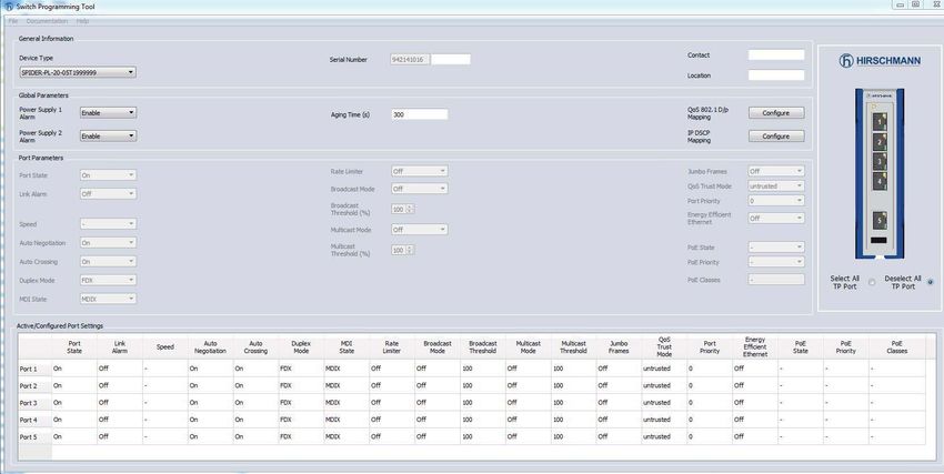
Release 10 04/2021 415 Configuration (optional)
The device is immediately ready for operation with its default settings, from
the factory.
The device allows you to change the settings according to your requirements
using the USB interface.
You can find the configuration parameters described in a separate overview.
See table 8 on page 46.
Prerequisite:
Install the Switch Programming Tool on your computer. You can download
the software for free on the Belden catalog: https://catalog.belden.com
Perform the following work steps:
Connect a storage medium to your PC.
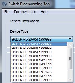
Start the Switch Programming Tool.
Select your device variant from the drop-down list “Device Type”.
Installation SPIDER-PL
42 Release 10 04/2021 Modify the parameters in the highlighted areas according to your requirements.
Release 10 04/2021
Installation SPIDER-PL
43 Save the configuration file to the storage medium.
Disconnect the storage medium from your PC.
Transfer the configuration data to your device by following these steps:
Verify that the device is switched off.
Connect the storage medium to the device.
Switch on the device.
The SPIDER device reads the csv file on the storage medium and adopts
the settings. During this time, the LED “LS/DA” flashes alternately in
yellow/green.
Installation SPIDER-PL
44 Release 10 04/2021Release 10 04/2021
Installation SPIDER-PL
Parameter Values Default values Comment
global PSU alarm PSU 1/2 enabled / PSU 1 / 2 enabled
disabled
Aging time Aging time in s 300 s
QoS 802.1p mapping VLAN Priority 0 ... 7 VLAN Priority Traffic Class
Traffic Class 0 ... 3 0 1
1 0
2 0
3 1
4 2
5 2
6 3
7 3
QoS DSCP mapping DSCP value 0 ... 63 See “DSCP mapping table” on page 46.
Traffic Class 0 ... 3
per port Flow control enabled / disabled disabled
Port admin state enabled / disabled enabled
Jumbo frames enabled / disabled disabled Only on GE ports
Broadcast storm enabled / disabled disabled Ingress filtering
protection
Broadcast storm 0% ... 100% 100%
threshold
Multicast storm enabled / disabled disabled Ingress filtering
protection
Multicast storm threshold 0% ... 100% 100%
QoS Trust Mode untrusted, trustDot1p, trustDot1 This also includes VLAN 0 mode for
trustIpDscp Profinet applications.
Port based priority 0 .. 7 0
Link alarm enabled / disabled disabled
Table 7: Configuration parameters
4546
Parameter Values Default values Comment
per TP port Autonegotiation enabled / disabled enabled
Speed 100 Mbit/s, 10 Mbit/s 100 Mbit/s Only if autonegotiation is disabled, no
forced mode 1000 Mbit/s
Duplex mode FDX / HDX FDX Only if autonegotiation is disabled
Autocrossing enabled / disabled enabled Only if autonegotiation is disabled
MDI state MDI-X MDI-X Only if autonegotiation is disabled
EEE enabled / disabled disabled Only for GE ports
per Fiber port Duplex mode FDX / HDX FDX
Table 7: Configuration parameters
d2/d1 0 1 2 3 4 5 6
0: 1 0 0 1 2 3 3
1: 1 0 0 1 2 3 3
2: 1 0 0 2 2 3 3
3: 1 0 0 2 2 3 3
4: 1 0 1 2 2 3
5: 1 0 1 2 2 3
6: 1 0 1 2 2 3
7: 1 0 1 2 2 3
8: 0 0 1 2 3 3
9: 0 0 1 2 3 3
Installation SPIDER-PL
Table 8: DSCP mapping table
Release 10 04/20215.1 Configuration readout You can read out the configuration using a storage medium. Perform the following work steps: Create a text file in the root directory of the storage medium. Rename the text file to “ShowRunningConfiguration.txt”. Connect the storage medium to the device. Restart the device by disconnecting the power supply for a moment. When the text file “ShowRunningConfiguration.txt” in the root directory of the device is found, the device creates a file with the current configuration. You find this file in the root directory of the storage medium under the name “RunningConfig.txt”. Installation SPIDER-PL Release 10 04/2021 47
6     Monitoring the ambient air temperature
Operate the device below the specified maximum ambient air temperature
exclusively.
See “General technical data” on page 53.
The ambient air temperature is the temperature of the air at a distance of
5 cm (2 in) from the device. It depends on the installation conditions of the
device, for example the distance from other devices or other objects, and the
output of neighboring devices.

                                                         Installation SPIDER-PL
48                                                              Release 10 04/2021
7 Maintenance and service When designing this device, Hirschmann largely avoided using high-wear parts. The parts subject to wear and tear are dimensioned to last longer than the lifetime of the product when it is operated normally. Operate this device according to the specifications. Relays are subject to natural wear. This wear depends on the frequency of the switching operations. Check the resistance of the closed relay contacts and the switching function depending on the frequency of the switching operations. Depending on the degree of pollution in the operating environment, check at regular intervals that the ventilation slots in the device are not obstructed. Note: You find information on settling complaints on the Internet at http:// www.beldensolutions.com/en/Service/Repairs/index.phtml. Installation SPIDER-PL Release 10 04/2021 49
8 Disassembly
8.1 Removing an SFP transceiver (optional)
Figure 4: De-installing SFP transceivers: De-installation sequence
Perform the following work steps:
Open the locking mechanism of the SFP transceiver (1).
Pull the SFP transceiver out of the slot via the open locking
mechanism (2).
Close the SFP transceiver with the protection cap (3).
8.2 Removing the device
WARNING
ELECTRIC SHOCK
Disconnect the grounding only after disconnecting all other cables.
Failure to follow this instruction can result in death, serious injury, or
equipment damage.
To prepare the deinstallation, perform the following work steps:
Disconnect the data cables.
Disable the supply voltage.
Disconnect the terminal blocks.
Disconnect the grounding.
Installation SPIDER-PL
50 Release 10 04/2021To remove the device from the DIN rail, perform the following work steps:
Insert a screwdriver horizontally below the casing into the locking gate.
Without tilting the screwdriver, pull the locking gate down and tilt the
device upwards.
1 2
Installation SPIDER-PL
Release 10 04/2021 51 Device variants SPIDER PL-20-16T1... , SPIDER PL-20-
24T1... , SPIDER PL-30-24T1...
WARNING
ELECTRIC SHOCK
Disconnect the grounding only after disconnecting all other cables.
Failure to follow this instruction can result in death, serious injury, or
equipment damage.
To prepare the deinstallation, perform the following work steps:
Disconnect the data cables.
Disable the supply voltage.
Disconnect the terminal blocks.
Disconnect the grounding.
To remove the device from the DIN rail, perform the following work steps:
Press the device downwards and pull it out from under the DIN rail.
1
2
Installation SPIDER-PL
52 Release 10 04/20219 Technical data
9.1 General technical data
Dimensions SPIDER-PL-20... See “Dimension drawings”
W×H×D SPIDER-PL-30... on page 55.
SPIDER-PL-40...
Weight SPIDER-PL-20-05T1999999TY9HHHH 400 g (14.11 oz)
SPIDER-PL-20-01T1M29999TY9HHHH 390 g (13.7 oz)
SPIDER-PL-20-01T1S29999TY9HHHH 390 g (13.7 oz)
SPIDER-PL-20-04T1M29999TY9HHHH 430 g (13.83 oz)
SPIDER-PL-20-04T1M49999TY9HHHH 400 g (14.11 oz)
SPIDER-PL-20-04T1S29999TY9HHHH 400 g (14.11 oz)
SPIDER-PL-20-06T1Z6Z6Z6TY9HHHH 530 g (18.70 oz)
SPIDER-PL-20-07T1S2S299TY9HHHH 510 g (17.99 oz)
SPIDER-PL-20-07T1M2M299TY9HHHH 510 g (17.99 oz)
SPIDER-PL-20-08T1M29999TY9HHHH 500 g (17.64 oz)
SPIDER-PL-20-08T1S29999TY9HHHH 500 g (17.64 oz)
SPIDER-PL-20-08T1999999TY9HHHH 430 g (13.83 oz)
SPIDER-PL-20-16T1999999TZ9HHHV 986 g (34.7 oz)
SPIDER-PL-20-24T1Z6Z699TZ9HHHV 1140 g (40.2 oz)
SPIDER-PL-30-24T1O6O699TZ9HHHV 1140 g (40.2 oz)
SPIDER-PL-40-01T1O69999TY9HHHH 400 g (14.11 oz)
SPIDER-PL-40-04T1O69999TY9HHHH 415 g (14.6 oz)
SPIDER-PL-40-05T1999999TY9HHHH 410 g (14.46 oz)
SPIDER-PL-40-08T1999999TY9HHHH 450 g (14.48 oz)
Power supply Configuration: Rated voltage 12 V DC ... 24 V DC
Hirschmann Voltage range incl. 9.6 V DC ... 32 V DC
standard maximum tolerances
(characteristic value
HH)
Configuration: Rated voltage 12 V DC ... 48 V DC
Extended voltage 24 V AC
range (characteristic Voltage range incl. 9.6 V DC ... 60 V DC
value HV) maximum tolerances 18 V AC ... 30 V AC
Connection type 6-pin terminal block, Tightening torque
characteristic value 0.51 Nm (4.5 lb-in)
HH
6-pin voltage terminal
with spring,
characteristic value
HK
Power loss buffer >10 ms
Back-up fuse ≤ 4 A, slow blow
Installation SPIDER-PL
Release 10 04/2021 53Signal contact Switching current max. 1 A SELV according
“FAULT” to IEC 60950-1 or ES1
according to IEC/
EN 62368-1
Switching voltage max. 60 V DC or
max. 30 V AC SELV
according to IEC 60950-1
or ES1 according to IEC/
EN 62368-1
Climatic conditions Ambient air -40 °C ... +70 °C
during operation temperaturea (-40 °F ... +158 °F)
Deratingb
Humidity 10 % ... 95 %
Air pressure min. 700 hPa
(+9842 ft; +3000 m)
Climatic conditions Ambient air temperaturea -40 °C ... +85 °C
during storage (-40 °F ... +185 °F)
Humidity 10 % ... 95 %
(non-condensing)
Air pressure min. 700 hPa
(+9842 ft; +3000 m)
Pollution degree 2
Protection classes Laser protection Class 1 in compliance with
IEC 60825-1
Degree of protection IP40
a. Temperature of the ambient air at a distance of 5 cm (2 in) from the device
b. For the device variant SPIDER PL-20-06T1Z6Z6Z6..., the maximum permitted ambient air
temperature has to be reduced to +60 °C (+140 °F).
Installation SPIDER-PL
54 Release 10 04/20219.2 Dimension drawings
9,9 9,9 9,9 mm
0.3 0.3 0.3 inch
135
135
5.3
5.3
135
5.3
56 56 39
2.2 2.2 1.5
SPIDER PL-20-08T1... SPIDER PL-20-06T1... SPIDER PL-20-04T1...
113 4,2 18
4.4 0.1 0.7
114,7 6,65 9,9 9,9 mm
4.52 0.26 0.39 0.39 inch
163,6
163,6
6.44
6.44
93,97 61
3.7 2.4
SPIDER PL-20-24T1... SPIDER PL-20-16T1...
SPIDER PL-30-24T1...
Figure 5: Dimensions of device variants SPIDER PL-20... and SPIDER PL-30...
Installation SPIDER-PL
Release 10 04/2021 559,9 9,9 9,9 mm
0.3 0.3 0.3 inch
135
5.3
135
5.3
135
5.3
49 39 39
1.9 1.5 1.5
SPIDER PL-40-08T1... SPIDER PL-40-05T1... SPIDER PL-040-01T1...
113 4,2 18
4.4 0.1 0.7
Figure 6: Dimensions of device variants SPIDER-PL-40...
Installation SPIDER-PL
56 Release 10 04/20219.3 Immunity
Release 10 04/2021
Installation SPIDER-PL
Immunity Standard Marine Railway Sub-station
applicationsa applicationsb applications applicationsd
(trackside)c
IEC 60068-2-6, test Fc Vibration 5 Hz ... 8.4 Hz with 2 Hz ... 13.2 Hz — 2 Hz ... 9 Hz with
3.5 mm (0.14 in) with 1 mm (0.04 in) 3 mm (0.11 in)
amplitude amplitude amplitude
8.4 Hz ... 150 Hz 13.2 Hz ... 200 Hz — 9 Hz ... 200 Hz with
with 1 g with 0.7 g 1g
— — — 200 Hz ... 500 Hz
with 1.5 g
IEC 60068-2-27, test Ea Shock 15 g at 11 ms — — 10 g at 11 ms
579.4 Electromagnetic compatibility (EMC)
58
Note: Use shielded data cables for gigabit transmission via copper cables. Use shielded data cables for all transmission
rates to meet the requirements according to EN 50121-4 and marine applications.
EMC interference emission Standard Marine Railway Sub-station
applicationsa applicationsb applications applicationsd
(trackside)c
Radiated emission
EN 55032 Class A Class A Class A Class A
DNV Guidelines — EMC 1 — —
FCC 47 CFR Part 15 Class A Class A Class A Class A
EN 61000-6-4 Fulfilled Fulfilled Fulfilled Fulfilled
Conducted emission
EN 55032 Supply connection Class A Class A Class A Class A
DNV Guidelines Supply connection — EMC 1 — —
FCC 47 CFR Part 15 Supply connection Class A Class A Class A Class A
EN 61000-6-4 Supply connection Fulfilled Fulfilled Fulfilled Fulfilled
EN 55032 Telecommunication Class A Class A Class A Class A
connections
EN 61000-6-4 Telecommunication Fulfilled Fulfilled Fulfilled Fulfilled
connections
a. EN 61131-2, CE, FCC – applies to all devices
b. Merchant Navy – applies to devices with the approval codes UY, WV, WW
Installation SPIDER-PL
c. EN 50121-4 – applies to devices with the approval codes TY, WV, WW
d. EN 61850-3, IEEE 1613 – applies to devices with the approval codes WW
Release 10 04/2021Release 10 04/2021
Installation SPIDER-PL
EMC interference immunity Standard Marine Railway Sub-station
applicationsa applicationsb applications applicationsd
(trackside)c
Electrostatic discharge
EN 61000-4-2 Contact discharge ±4 kV ±6 kV ±6 kV ±8 kV
IEEE C37.90.3
EN 61000-4-2 Air discharge ±8 kV ±8 kV ±8 kV ±15 kV
IEEE C37.90.3
Electromagnetic field
EN 61000-4-3 max. 10 V/m max. 10 V/m max. 20 V/m max. 10 V/m
IEEE 1613 — — — max. 35 V/m
Fast transients (burst)
EN 61000-4-4 Supply connection ±2 kV ±2 kV ±2 kV ±4 kV
IEEE C37.90.1
EN 61000-4-4 Data line ±4 kV ±4 kV ±2 kV ±4 kV
IEEE C37.90.1
Voltage surges - DC supply connection
EN 61000-4-5 line/ground ±2 kV ±2 kV ±2 kV ±2 kV
IEEE 1613 line/ground — — — ±5 kV
EN 61000-4-5 line/line ±1 kV ±1 kV ±1 kV ±1 kV
Voltage surges - data line
EN 61000-4-5 line/ground ±1 kV ±1 kV ±2 kV ±2 kV
Conducted disturbances
EN 61000-4-6 150 kHz ... 80 MHz 10 V 10 V 10 V 10 V
Damped oscillation – DC supply connection
EN 61000-4-12 line/ground — — — 2.5 kV
IEEE C37.90.1
EN 61000-4-12 line/line — — — 1 kV
IEEE C37.90.1
Damped oscillation – data line
EN 61000-4-12 line/ground — — — 2.5 kV
IEEE C37.90.1
5960
EMC interference immunity Standard Marine Railway Sub-station
applicationsa applicationsb applications applicationsd
(trackside)c
EN 61000-4-12 line/line — — — ±1 kV
Pulse magnetic field
EN 61000-4-9 — — 300 A/m —
Installation SPIDER-PL
Release 10 04/20219.5 Network range
Release 10 04/2021
Installation SPIDER-PL
Note: The line lengths specified for the transceivers apply for the respective fiber data (fiber attenuation and Bandwidth
Length Product (BLP)/ Dispersion).
Product code Modea Wave length Fiber System Example for F/O Fiber attenuation BLPc/
M-SFP-... attenuation cable lengthb Dispersion
-SX/LC... MM 850 nm 50/125 µm 0 dB ... 7.5 dB 0 km ... 0.55 km 3.0 dB/km 400 MHz×km
(0 mi ... 0.34 mi)
-SX/LC... MM 850 nm 62.5/125 µm 0 dB ... 7.5 dB 0 km ... 0.275 km 3.2 dB/km 200 MHz×km
(0 mi ... 0.17 mi)
-MX/LC EEC MM 1310 nm 50/125 µm 0 dB ... 12 dB 0 km ... 1.5 km 1.0 dB/km 800 MHz×km
(0 mi ... 0.93 mi)
-MX/LC EEC MM 1310 nm 62.5/125 µm 0 dB ... 12 dB 0 km ... 0.55 km 1.0 dB/km 500 MHz×km
(0 mi ... 0.34 mi)
-LX/LC... MM 1310 nmd 50/125 µm 0 dB ... 10.5 dB 0 km ... 0.55 km 1.0 dB/km 800 MHz×km
(0 mi ... 0.34 mi)
-LX/LC... MM 1310 nme 62.5/125 µm 0 dB ... 10.5 dB 0 km ... 0.55 km 1.0 dB/km 500 MHz×km
(0 mi ... 0.34 mi)
-LX/LC... SM 1310 nm 9/125 µm 0 dB ... 10.5 dB 0 km ... 20 km 0.4 dB/km 3.5 ps/(nm×km)
(0 mi ... 12.43 mi)f
-LX+/LC... SM 1310 nm 9/125 µm 5 dB ... 20 dB 14 km ... 42 km 0.4 dB/km 3.5 ps/(nm×km)
(8.70 mi ... 26.10 mi)
-LH/LC... LH 1550 nm 9/125 µm 5 dB ... 22 dB 23 km ... 80 km 0.25 dB/km 19 ps/(nm×km)
(14.29 mi ... 49.71 mi)
-LH+/LC LH 1550 nm 9/125 µm 15 dB ... 30 dB 71 km ... 108 km 0.25 dB/km 19 ps/(nm×km)
(44.12 mi ... 67.11 mi)
-LH+/LC LH 1550 nm 9/125 µm 15 dB ... 30 dB 71 km ... 128 km 0.21 dB/km (typically) 19 ps/(nm×km)
(44.12 mi ... 79.54 mi)
Table 9: F/O port 1000BASE-FX (SFP fiber optic Gigabit Ethernet Transceiver)
a. MM = Multimode, SM = Singlemode, LH = Singlemode Longhaul
61
b. Including 3 dB system reserve when compliance with the fiber data is observed.c. Using the bandwidth-length product is inappropriate for expansion calculations.
62
d. With F/O adapter compliant with IEEE 802.3-2002 Clause 38 (single-mode fiber offset-launch mode conditioning patch cord).
e. With F/O adapter compliant with IEEE 802.3-2002 Clause 38 (single-mode fiber offset-launch mode conditioning patch cord).
f. Including 2.5 dB system reserve when compliance with the fiber data is observed.
Product code Modea Wave length Wave length Fiber System Example for F/O Fiber Dispersion
M-SFP-BIDI... TX RX attenuation cable lengthb attenuation
Type A LX/LC EEC SM 1310 nm 1550 nm 9/125 µm 0 dB ... 11 dB 0 km ... 20 km 0.4 dB/km 3.5 ps/(nm×km)
(0 mi ... 12.43 mi)
Type B LX/LC EEC SM 1550 nm 1310 nm 9/125 µm 0 dB ... 11 dB 0 km ... 20 km 0.25 dB/km 19 ps/(nm×km)
(0 mi ... 12.43 mi)
Type A LH/LC EEC LH 1490 nm 1590 nm 9/125 µm 5 dB ... 24 dB 23 km ... 80 km 0.25 dB/km 19 ps/(nm×km)
(14.29 mi ... 49.71 mi)
Type B LH/LC EEC LH 1590 nm 1490 nm 9/125 µm 5 dB ... 24 dB 23 km ... 80 km 0.25 dB/km 19 ps/(nm×km)
(14.29 mi ... 49.71 mi)
Table 10: F/O port (bidirectional Gigabit Ethernet SFP transceiver)
a. MM = Multimode, SM = Singlemode, LH = Singlemode Longhaul
b. Including 3 dB system reserve when compliance with the fiber data is observed.
Product code Modea Wave length Fiber System Example for F/O Fiber attenuation BLP/Dispersion
M-FAST-SFP-... attenuation cable lengthb
-MM/LC... MM 1310 nm 50/125 µm 0 dB ... 8 dB 0 km ... 5 km 1.0 dB/km 800 MHz×km
(0 mi ... 3.11 mi)
-MM/LC... MM 1310 nm 62.5/125 µm 0 dB ... 11 dB 0 km ... 4 km 1.0 dB/km 500 MHz×km
Installation SPIDER-PL
(0 mi ... 2.49 mi)
-SM/LC... SM 1310 nm 9/125 µm 0 km ... 25 km 0.4 dB/km 3.5 ps/(nm×km)
(0 mi ... 15.53 mi)
Release 10 04/2021
-SM+/LC... SM 1310 nm 9/125 µm 10 dB ... 29 dB 25 km ... 65 km 0.4 dB/km 3.5 ps/(nm×km)
(15.53 mi ... 40.39 mi)
Table 11: Fiber port 100BASE-FX (SFP fiber optic Fast Ethernet Transceiver)You can also read