SOLECTRIA XGI 1500 Installation and Operation Guide
←
→
Page content transcription
If your browser does not render page correctly, please read the page content below
ommercial   1500VDC String Inverter

            SOLECTRIA® XGI 1500
            Installation and Operation Guide
            Models:
             XGI 1500-125/125-UL      XGI 1500-125/125-UL-A
             XGI 1500-125/150-UL      XGI 1500-125/150-UL-A
             XGI 1500-150/166-UL      XGI 1500-150/166-UL-A
             XGI 1500-166/166-UL      XGI 1500-166/166-UL-A
             XGI 1500-125/125-3S      XGI 1500-166/166-3S
Table of
Installation and Operation Guide SOLECTRIA XGI 1500 (Rev N, 22 JUN 2022)

Contents
    IMPORTANT SAFETY INSTRUCTIONS .................................................................................................... 4
          Hazard Symbols .................................................................................................................................. 4
          Symbols on Labels .............................................................................................................................. 4
          General Safety Messages ................................................................................................................... 5
          Status Panel ........................................................................................................................................ 6
    Overview .................................................................................................................................................... 7
          Inverter Overview ................................................................................................................................ 7
          Inverter Placement ............................................................................................................................ 10
          Unpacking ......................................................................................................................................... 11
    Installation ................................................................................................................................................ 11
          Installation Sequence ........................................................................................................................ 11
          Inverter Size, Spacing and Mounting ................................................................................................. 12
          Wiring ................................................................................................................................................ 15
          Transformer Configuration ................................................................................................................. 19
          Equipment Grounding........................................................................................................................ 20
          AC Connections ................................................................................................................................ 21
          AC Breaker Specifications ................................................................................................................. 22
          DC Connections ................................................................................................................................ 23
          DC Connection Using the XGI Remote or Attachable Combiner ........................................................ 24
          DC Connection Using the XGI Attachable Combiner Box .................................................................. 26
          Conduit Sealing ................................................................................................................................. 28
          Antenna Mounting ............................................................................................................................. 29
          Replace Wiring Box Cover ................................................................................................................. 29
    Startup and Verification Test .................................................................................................................... 30
          Startup Checklist ............................................................................................................................... 30
          Startup Steps..................................................................................................................................... 30
          Commissioning Test .......................................................................................................................... 31
    Communication Installation and User Interface......................................................................................... 32
          Connection to the Internet ................................................................................................................. 32
          Communication Conductors .............................................................................................................. 32
          Connecting Multiple Inverters ............................................................................................................ 32
          XGI Gateway Inverters Firewall ......................................................................................................... 35
          Networking with Other Devices .......................................................................................................... 35

                                                                                                                                                         2 of 73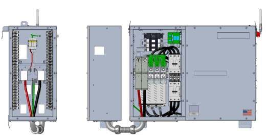
Installation and Operation Guide SOLECTRIA XGI 1500 (Rev N, 22 JUN 2022)

          Monitoring Compatibility .................................................................................................................... 36
          Third-Party Data Acquisition System (DAS) Connection .................................................................... 36
          Static IP Configuration, Gateway Inverter .......................................................................................... 37
          Port Forwarding ................................................................................................................................. 37
          Static Routing .................................................................................................................................... 39
          Manage Cluster IP Address ............................................................................................................... 40
          Communication and I/O Ports............................................................................................................ 41
    Graphical User Interface ........................................................................................................................... 42
          XGI Terminology ............................................................................................................................... 42
          Graphical User Interface (GUI) Overview .......................................................................................... 42
          Menu Structure .................................................................................................................................. 48
    Firmware Updates .................................................................................................................................... 49
          Automatic Remote Firmware Updates ............................................................................................... 49
          Manual Firmware Updates, Locally.................................................................................................... 49
          Manual Firmware Updates, Remote Server ....................................................................................... 49
          Manual Firmware Updates, Remote Access Portal ............................................................................ 49
    Communication Commissioning ............................................................................................................... 51
          Communication Commissioning Checklist ......................................................................................... 51
    Maintenance and Troubleshooting............................................................................................................ 52
          Event Codes ...................................................................................................................................... 52
          Regular Preventative Maintenance .................................................................................................... 57
    Specifications ........................................................................................................................................... 61
          General Specifications....................................................................................................................... 61
           Enclosure .......................................................................................................................................... 61
          Voltage and Frequency Limits and Trip Times ................................................................................... 62
          Temperature and Altitude .................................................................................................................. 63
          P-Q Curves ....................................................................................................................................... 65
    Options ..................................................................................................................................................... 69
          Attachable Combiner Box (Optional) ................................................................................................. 69
          Remote Combiner (Optional) ............................................................................................................. 71
    Appendix .................................................................................................................................................. 72
          Warranty and RMA Instructions ......................................................................................................... 72
          Yaskawa Solectria Solar Contact Information .................................................................................... 72
          Authorization to Mark......................................................................................................................... 73

                                                                                                                                                         3 of 73
Installation and Operation Guide SOLECTRIA XGI 1500 (Rev N, 22 JUN 2022)

    IMPORTANT SAFETY INSTRUCTIONS
     Hazard Symbols
                                       Table 1-1 Hazard Symbols

                  DANGER indicates a hazardous situation, which, if not avoided, will result in serious
                  injury or death.

                  WARNING indicates a hazardous situation, which, if not avoided, could result in serious
                  injury or death.

                  CAUTION indicates a hazardous situation, which, if not avoided, will result in minor or
                  moderate injury.

                  NOTICE indicates a hazardous condition, which, if not avoided, could result in equipment
                  working abnormally or property loss.

                  INFO indicates important supplementary information to use the product effectively.

     Symbols on Labels
                                   Table 1-2 Explanation of Symbols

                  AC Signal

                  DC Signal

                  Equipment Ground

                  AC Power Phase

                  Off

                  On

                  Refer to Operating Instructions

                  Caution: Risk of Electric Shock

                  Caution: Risk of Electric Shock
                  Timed Discharge

                                                                                                       4 of 73
Installation and Operation Guide SOLECTRIA XGI 1500 (Rev N, 22 JUN 2022)

     General Safety Messages

                  Electric Shock Hazard
                  Components with hazardous voltage and energy will electrocute operator. Operator shall
                  avoid touching live components with hazardous voltage and energy.

                  Unqualified Operator Hazard
                  Operator may cause a hazardous situation by making incorrect installation or wiring
                  connections. A qualified technician shall do all installation and wiring connections to
                  comply with all local, national, or country specific guidelines for safety.

                  Electrical Shock Hazard
                  Operator may contact components with hazardous voltage and energy. Use proper safety
                  equipment including Personal Protective Equipment (PPE) when de-energizing the unit.
                  De-energize the unit, wait 5 minutes, and verify the absence of voltage before opening the
                  equipment or removing any protective shields.

                  General Damage to Equipment
                  Attempting to service the inverter improperly may result in damage. Contact Yaskawa
                  Solectria Solar Technical Support for maintenance.

                  Read and Follow Instructions
                  Failure to read and follow instructions may void the warranty. Install the inverter according
                  to the instructions in this manual.

                                   SAVE THESE INSTRUCTIONS
                            This manual contains instructions for models:
                       XGI 1500-125/125-UL                  XGI 1500-125/125-UL-A
                       XGI 1500-125/150-UL                  XGI 1500-125/150-UL-A
                       XGI 1500-150/166-UL                  XGI 1500-150/166-UL-A
                       XGI 1500-166/166-UL                  XGI 1500-166/166-UL-A
                       XGI 1500-125/125-3S                  XGI 1500-166/166-3S

                                                                                                         5 of 73
Installation and Operation Guide SOLECTRIA XGI 1500 (Rev N, 22 JUN 2022)

      Status Panel
The status panel consists of five LEDs that provide useful information to the user regarding the function of the
inverter. LEDs are shown in Figure 1-1 and defined in Table 1-3.

                                            Figure 1-1 Status Panel

                             Table 1-3 Explanation of Symbols on Status Panel

                                       Ready (Yellow)
                                       On: Inverter is initialized and ready to operate
                                       Off: Inverter is not ready to operate

                                       Network and Communication (Yellow)
                                       On: Network and communication services are working properly
                                       Off: Network and communication services are offline

                                       Power (Yellow)
                                       On: Inverter is generating AC power
                                       Off: Inverter is not generating AC power

                                       Maintenance (Yellow)
                                       On: Inverter needs maintenance or service
                                       Off: Inverter does not need maintenance or service

                                       Power Fault (Red)
                                       On: Power fault that needs service and may be a hazard
                                       Off: There is no power fault

                                                                                                          6 of 73
Installation and Operation Guide SOLECTRIA XGI 1500 (Rev N, 22 JUN 2022)
Overview
Inverter Overview
A solar inverter converts DC power from solar modules to AC power, and exports it to the electrical grid as
shown in Figure 2-1. The SOLECTRIA XGI 1500 is a state-of-the-art inverter designed and made in the USA
using global components and is compliant with the Buy American Act.
Figure 2-1 Inverter Usage
2.1.1 Inverter Features
High conversion efficiency using 3-level conversion technology.
o Max efficiency: 99.0%
o CEC efficiency: 98.5%
Grid adaptability
o Supports multiple grid standards
o Certified to UL1741SA for CA Rule 21 compliance
o Adjustable reactive power
o Adjustable power factor (PF) ±0.8
o Remote power curtailment
Ethernet connectivity
Wi-Fi accessible user interface
Protective enclosure: NEMA 4X rated enclosure allows for outdoor use.
Flexible design: The SOLECTRIA XGI 1500 series inverters provide a flexible solution for both distributed
and centralized “virtual central” system architecture. Two optional versions of combiners are offered: the
Attachable Combiner (CA-XGI1500 series) and the Remote Combiner (CR-XGI1500 series) with 16, 20,
24, 26 or 28 fuse positions.
7 of 73
Installation and Operation Guide SOLECTRIA XGI 1500 (Rev N, 22 JUN 2022)
2.1.2 Inverter Protection Features
Short-circuit protection
Anti-islanding protection
Input and output surge protection
Input over-current protection
Self-monitoring variables:
o DC input insulation resistance with respect to ground
o AC output voltage and frequency
o Leakage current to ground
o DC injection in AC output
o Internal ambient temperature
o IGBT module temperature
2.1.3 Communication Overview
Users can communicate with the SOLECTRIA XGI 1500 using a Wi-Fi-enabled smart device, such as a laptop,
tablet, or smartphone. The SOLECTRIA XGI 1500 monitors internal variables which are sent via a modem or
gateway to the Internet cloud. In the cloud, these data are stored on the SRV server where they can be
accessed by the end user (additional fee applies). Add-ons such as a weather station and a Data Acquisition
System (DAS) are supported using Ethernet cable.
Figure 2-2 Communications Overview
8 of 73
Installation and Operation Guide SOLECTRIA XGI 1500 (Rev N, 22 JUN 2022)

2.1.4 Inverter Features

    Figure 2-3 SOLECTRIA XGI 1500 Inverter Features: Front (Left), Right Side (Right), and Bottom
                                            (Bottom)

                                                                                               9 of 73
Installation and Operation Guide SOLECTRIA XGI 1500 (Rev N, 22 JUN 2022)

      Inverter Placement
The SOLECTRIA XGI 1500 inverter is rated for outdoor use and will operate when exposed to direct sunlight or
rain. To obtain the best performance and ensure longevity of the inverter, it is recommended to mount the inverter
out of the direct sunlight.

                     Inverter Facing Direction
                     It is recommended to install the inverter facing north to minimize direct sun exposure.

            Figure 2-4 Inverter Environment (Left to Right) Direct Sunlight, Shaded, and Rain

Mount the inverter vertically and level to the ground. Do not install the inverter in a pitched/tilted/angled
orientation.

                   Figure 2-5 Inverter Mounted Correctly -- Vertical and Level to Ground

                                                                                                                10 of 73
Installation and Operation Guide SOLECTRIA XGI 1500 (Rev N, 22 JUN 2022)
Unpacking
When storing the packaged inverters, keep them in an area where they will not get damaged or flooded. Storage
temperatures should be maintained in the range -40°F to +167°F (-40°C to +75°C). Open the box carefully to
avoid damaging the contents.
Table 2-1 Contents of Box
1. Inverter (XGI 1500-166/166-UL, XGI 1500-150/166-UL, XGI 1500-125/150-UL, XGI 1500-125/125-
UL, XGI 1500-166/166-UL-A, XGI 1500-150/166-UL-A, XGI 1500-125/150-UL-A, XGI 1500-125/125-
UL-A, XGI 1500-166/166-3S, or XGI 1500-125/125-3S)
2. Voltage-Frequency Test Report
3. One page information sheet for Wi-Fi connection to smart device
4. Hardware Kit containing:
a. Antenna for Wi-Fi connection to smart device.
b. 90 degree coaxial connection for antenna.
Installation
Installation Sequence
1. Remove the inverter from its crate and properly dispose of the packaging material.
2. Secure the inverter to the structure, carefully observing the lifting hazard below.
Lifting Heavy Object Hazard
Proper lifting technique must be used in order to avoid injuries.
Lift into place with at least two people or using a mechanical aid
3. Turn off the upstream AC breaker and apply a lock.
4. Turn off the AC switch on the inverter.
5. Turn off the DC switch on the inverter.
6. Remove the wiring box cover.
7. Confirm that the PV output circuit conductors (from a Combiner) are de-energized.
8. Connect the AC wires from the grid to the AC terminal block in the wiring box.
9. Connect the PV output circuit wires (from a Combiner) to the DC terminal block in the wiring box.
10. Connect the communication wires.
11. Replace the inverter cover.
12. Connect the antenna to the inverter using the 90-degree coaxial connection.
11 of 73Installation and Operation Guide SOLECTRIA XGI 1500 (Rev N, 22 JUN 2022)
Inverter Size, Spacing and Mounting
The dimensions of the XGI 1500 inverter are shown in Figure 3-1.
41.3 in
1048 mm
34.9 in
34.9 in 886 mm
886 mm
Figure 3-1 Inverter Dimensions
Mount the inverter to 15/8 inch strut channel as shown in Figure 3-4. Ensure that the strut channel structure is
capable of supporting 270 lbs (122 kg) plus an effective safety margin. Structural integrity of the strut structure
is the responsibility of the installer. Space the inverters no closer than shown in Figure 3-2 for thermal exhaust
and wiring clearance. Keep this area free from debris, vegetation, and other obstructions.
Figure 3-2 Inverter Minimum Spacing and Mounting – Top View
12 of 73Installation and Operation Guide SOLECTRIA XGI 1500 (Rev N, 22 JUN 2022)
Refer to Figure 3-3 to space strut channels for mounting. The holes on the bottom use the centerline as the
reference point and the hook at the top uses the top of the upper strut channel as its reference point. Use two 8
mm (5/16 in) bolts (not provided) to connect the bottom brackets to the strut channel.
28.625 in
727 mm
Centerline of Strut
32.625 in
Figure 3-3 Mounting Holes – Rear View
Attach the inverter, with its mounting brackets in place, to the strut channel as shown in Figure 3-54. The top
brackets fit over the upper strut bar to hang the inverter while securing the upper and lower brackets to the strut
channel. The brackets are attached to the inverter in the factory.
Figure 3-4 Mounting the Inverter to the Strut Channels
13 of 73Installation and Operation Guide SOLECTRIA XGI 1500 (Rev N, 22 JUN 2022)
When positioned on the strut, the inverter and strut channels should appear as in Figure 3-5. To secure the
inverter in place, use two 8mm (5/16 in) bolts (not provided) through the holes provided in the top face of the upper
brackets, and two more through the front face of the lower bracket.
CL
27.8 in
706 mm
CL
Slotted Holes for 8mm Bolts (not supplied)
Figure 3-5 Inverter Mounted to Strut Channels, Back View (Upper Image) and Top View (Lower Image)
Lifting Heavy Object Hazard
Proper lifting technique must be used in order to avoid injuries.
Lifting requires at least two people or a mechanical hoist to install the Inverter.
14 of 73Installation and Operation Guide SOLECTRIA XGI 1500 (Rev N, 22 JUN 2022)
Wiring
Turn the AC Switch to OFF before wiring. The AC switch is located on the right side of the inverter (Figure 2-3.)
Turn AC Switch to OFF
Verify the absence of AC voltage.
Use conductors with a temperature rating of 90°C. Terminations are rated for 90°C rated conductors. Ensure
that all connections are in compliance with NEC ANSI/NFPA 70 and local electrical codes. With longer wire runs,
larger conductors than required by code are often used to reduce the voltage drop. See Section 3.6 for AC
connection specifications and Section 3.8.1 for DC connection specifications.
Before wiring, mark locations of conduit entry on the removable gland plate (located on the bottom of the
inverter). Remove the gland plate before drilling or punching holes to prevent metal debris from entering the
inverter enclosure. Re-attach the gland plate to install conduit fittings and conduit. Keep AC and DC connections
in separate conduit. All conduit used for connections must use rain tight or wet location connectors that comply
with UL 514B to maintain the enclosure’s Type 4X rating. Conduit holes or other modifications to the enclosure
are not permitted anywhere on the enclosure except for the removable conduit panel.
3.3.1 Remove Cover on Wiring Box
Use a #3 Phillips-head screwdriver to remove the 10 screws from the cover of the Wiring Box, as shown in Figure
3-6.
Figure 3-6 Wiring Box Cover Screws (Quantity 10)
When replacing the cover, all 10 screws must be installed to maintain the enclosure rating.
This prevents water from entering the enclosure that could potentially damage the
equipment. Damage due to water is not covered under warranty.
15 of 73Installation and Operation Guide SOLECTRIA XGI 1500 (Rev N, 22 JUN 2022)
With the cover removed, the inverter is ready for wiring, as shown in Figure 3-7.
GND
M8 Stud
and Nut NEUTRAL
Figure 3-7 Wiring Box Connections
3.3.2 Removable Conduit Panel
All conduit entries must pass through the removable conduit panel. All modifications to the removable panel
must occur when the panel is detached from the inverter. This prevents metal shavings and other debris from
potentially damaging the inverter. Remove the 10 screws using a #3 Phillips-head screwdriver. When
modifications are complete, replace all 10 screws and torque to 25 in-lbs (2.8 Nm).
All modifications to the conduit panel must be contained within the region shown in Figure 3-8. For inverters
paired with the attachable combiner box, the removable conduit panels for each require a 2” hole to
accommodate the provided conduit and wire assembly. Modify the removable panels so this hole is located as
shown in Figure 3-9 for the inverter and as shown in Figure 3-10 for the attachable combiner.
Conduits entering the inverter often allow condensation to form inside the inverter
enclosure. Use an appropriately rated sealant for these conduits to prevent
condensation. Condensation inside the inverter may cause irreparable damage and is
not covered under warranty.
16 of 73Installation and Operation Guide SOLECTRIA XGI 1500 (Rev N, 22 JUN 2022)
Figure 3-8 Removable Conduit Panel – Entry Locations
17 of 73Installation and Operation Guide SOLECTRIA XGI 1500 (Rev N, 22 JUN 2022)
Figure 3-9 DC Conduit Hole Location for Inverters Paired with Attachable Combiners
Figure 3-10 Conduit Hole Location for Attachable Combiners
18 of 73Installation and Operation Guide SOLECTRIA XGI 1500 (Rev N, 22 JUN 2022)
Transformer Configuration
Grid Mismatch
If the grid does not match the requirements, the inverter will not start and damage may
occur. Check with your local electric utility before selecting a grid standard.
The system must comply with National Electrical Code ANSI/NFPA 70 and with all local
rules and safety regulations before the inverter can be operated.
The inverter must be connected to an isolation transformer provided by the customer that has a grounded Wye
configuration on the inverter side (see Figure 3-11). The neutral of this transformer must be grounded.
Wye With Neutral Wye Without Neutral
Figure 3-11 Permitted Transformer Configurations
The inverter cannot operate connected to a delta service, corner grounded service, or wye with fully insulated
Neutral. For more information, please refer to Solectria’s application note on this topic:
Interconnection Guidelines for Yaskawa Solectria Solar Transformerless Inverters.
19 of 73Installation and Operation Guide SOLECTRIA XGI 1500 (Rev N, 22 JUN 2022)
WYE with Floating Ground Delta with Floating Ground Delta with Corner Ground
Figure 3-12 Prohibited Transformer Configurations
Improper Transformer Configuration
Inverter will not run and may have hazardous current. Connect transformer in specified
configurations only. Incorrect transformer configuration may cause damage to the inverter.
Equipment Grounding
The XGI 1500 must be bonded using equipment grounding provisions. Do not attempt to ground either DC
pole. The XGI 1500 includes provisions for terminating equipment grounding conductors and other conductors
used for bonding. One M8 stud with an M8 external-tooth star nut is located inside the inverter wiring section
(Figure 3-13). Use a 13mm socket and torque to 90 in-lbs (12.2 N-m). On the exterior of the inverter is an M6
threaded insert (Figure 3-13). Torque this fastener to 39 in-lbs (4.4N-m)
M8 Stud
and Nut
Neutral
M6 Threaded Insert
Figure 3-13 Ground Connection Inside and Outside Inverter
Table 3-1 Grounding and Bonding Connection Specifications
Material XGI 1500-125/125 XGI 1500-125/150 XGI 1500-150/166 XGI 1500-166/166
4 to 1/0 AWG 4 to 1/0 AWG 4 to 1/0 AWG 4 to 1/0 AWG
Copper (21.1 to 53.5 mm2) (21.1 to 53.5 mm2) (21.1 to 53.5 mm2) (21.1 to 53.5 mm2)
Grounding
Conductor
Aluminum 2 to 1/0 AWG 2 to 1/0 AWG 2 to 1/0 AWG 2 to 1/0 AWG
(33.6 to 53.5 mm2) (33.6 to 53.5 mm2) (33.6 to 53.5 mm2) (33.6 to 53.5 mm2)
20 of 73Installation and Operation Guide SOLECTRIA XGI 1500 (Rev N, 22 JUN 2022)
AC Connections
The AC connections consist of the 3 AC Phases (L1, L2, and L3), Neutral and Ground. AC wires must be rated
for at least 600 VAC. Use wires no larger than shown in Table 3-2, and sized as required to comply with local
codes and the National Electrical Code.
Table 3-2 AC Connection Specifications
XGI 1500-166/166-xx, XGI 1500-150/166-xx
XGI 1500-125/150-xx, XGI 1500-125/125-xx
Maximum Allowed
AC Output
(L1, L2, L3) Conductors Cu and Aluminum: 600 kcmil, 1 or 2 conductors with lugs
(lug width 42mm or less)
Range Allowed
Neutral (Bonded to
Ground) Copper: 4 to 1/0 AWG
Aluminum: 2 to 1/0 AWG
Electric Shock Hazard
Components with hazardous voltage and energy will electrocute the operator.
Ensure AC power doesn’t flow into inverter. Verify with a multimeter.
Turn the AC Switch OFF before wiring. Wire the AC Connections as shown in Figure 3-14.
For the AC connections, use compression lugs with a single hole for a ½ in or M12 stud and sized for the wire
gauge used. The width of the lugs must be 42 mm, or less. Torque to 220 in-lbs (25 N-m) using an 18mm
socket and torque driver. A hex nut and washer are provided. The terminal block accepts single or parallel
conductor sets. See Figure 3-16 for the hardware assembly instructions.
Although a neutral terminal is available, a neutral conductor is not required for inverter operation. The neutral
terminal is bonded to chassis and only used for voltage sensing. If a neutral conductor is installed, torque the
neutral terminal based on the conductor size according to Table 3-3 using either 3/16 Allen hex key or a slot
torque driver.
Table 3-3 Neutral Terminal Torque Specifications
4 AWG (Cu) 2-1/0 AWG (Cu or Al)
(42.3 mm2) (42.4 to 53.5 mm2)
50 in-lbs 55 in-lbs
Neutral
(5.6 N-m) (6.2 N-m)
21 of 73Installation and Operation Guide SOLECTRIA XGI 1500 (Rev N, 22 JUN 2022)
Figure 3-14 AC Connections – Neutral and Ground (Left) and Phases (Right)
For aluminum connections, follow these steps to prepare the wires, one wire at a time.
a) Remove the appropriate amount of wire insulation
b) Use a wire brush to remove the oxidation layer from the aluminum conductors.
c) Immediately apply neutral dielectric grease (such as Noalox) and connect the cable to the terminal.
If the connection is not made within 30 seconds of applying the grease, repeat this process as an oxidized
layer may have formed on top of the conductor. An oxidized layer is a poor conductor which could lead to
thermal issues, production loss, or damage to the inverter.
Clockwise Phase Rotation: Ensure the inverter is installed with a clockwise phase rotation. A
counterclockwise phase rotation will prevent the inverter from running. If the inverter reports a PLL (Phase
Lock Loop) error or the frequency/voltage measurements seem incorrect, check your phase rotation. Swapping
any two AC conductors will reverse the phase rotation.
AC Breaker Specifications
The AC output of the Solectria XGI 1500 series inverters requires connection to a 3-pole AC breaker with ratings
as specified in Table 3-4.
Table 3-4 AC Breaker Specifications
XGI 1500- XGI 1500- XGI 1500- XGI 1500-
125/125-xx 125/150-xx 150/166-xx 166/166-xx
Minimum 150 A 200 A 200 A 200 A
AC Breaker Rating (3 pole, 600VAC) (3 pole, 600VAC) (3 pole, 600VAC) (3 pole, 600VAC)
22 of 73Installation and Operation Guide SOLECTRIA XGI 1500 (Rev N, 22 JUN 2022)
DC Connections
The PV source circuits must be combined external to the inverter using equipment such as the XGI Remote
Combiner box or the XGI Attachable Combiner box.
3.8.1 General DC Connection Information
The SOLECTRIA XGI 1500 has a single DC input into one MPPT zone.
Perform the calculations based on the total inverter nameplate AC power rating. With the maximum DC/AC ratios
shown in Table 3-5, at STC conditions (Equation 3.1), a user can connect up to 332 kWp for all XGI 1500 models.
Note for any application that may experience higher than 1000 W/m2 on a regular basis, a lower DC/AC ratio is
recommended. Also, the sum of the Isc rating of all PV source circuits, multiplied by 1.25, must be less than 500
A (Equation 3.2).
1.5, 1.66 2.0 at STC (3.1)
∑ ∗ 1.25 500A (3.2)
DC/AC Ratio and Isc Requirements
Both the DC/AC ratio and Isc limit requirements must be met.
Failure to stay within these limits may result in damage NOT covered under warranty.
3.8.2 DC Input Specifications
Table 3-5 DC Input Specifications
XGI 1500-125/125 XGI 1500-125/150 XGI 1500-150/166 XGI 1500-166/166
Max Operating DC
127 kW 127 kW 152 kW 169 kW
power
Max DC rated power
332 kW 332 kW 332 kW 332 kW
allowed
Absolute Max open
1500 VDC
circuit Voltage
Operating voltage 860 - 1450 VDC
Max power input
860 - 1250 VDC
voltage range (MPPT)
Maximum operating
148.3 A 148.3A 178.0A 197.7 A
input current
Maximum PV Current
500 A
(Isc x 1.25)
Maximum Allowed DC
2.6 2.6 2.2 2.0
to AC Ratio
Risk of Electric Shock or Fire
Use only with PV modules, DC conductors, switches, fuses, and fuse holders with a
maximum system voltage rating of 1500 VDC or higher.
23 of 73Installation and Operation Guide SOLECTRIA XGI 1500 (Rev N, 22 JUN 2022)
3.8.3 Fuses Configuration and Sizes
Refer to Table 3-6 for information regarding fuse sizes and configuration.
Table 3-6 Attachable Combiner Box
Number of DC Inputs 16, 20, 24, 26, 28
15 A, 20 A (16, 20, 24, 26 or 28 positions)
Fuse Rating Options
25 A (20 positions), 30 A (16 positions)
Fuse Configuration Both Poles Fused
Switch Configuration Both Poles Switched
Open Fuse Holders
Verify the absence of DC voltage and current when inserting or removing fuses.
Use Correct Fuses
Size the fuses following NEC requirements.
DC Connection Using the XGI Remote or Attachable Combiner
Wire the DC Connections as shown in Figure 3-15 using the wire sizes shown in Table 3-7.
DC
TERMINATIONS
+ -
Figure 3-15 DC Connections from an XGI Remote Combiner
24 of 73Installation and Operation Guide SOLECTRIA XGI 1500 (Rev N, 22 JUN 2022)
Table 3-7 DC Input Wire Size
XGI 1500- XGI 1500- XGI 1500- XGI 1500-
125/125-xx 125/150-xx 150/166-xx 166/166-xx
Minimum Wire Size 2/0 AWG 2/0 AWG 3/0 AWG 4/0 AWG
(Copper) (67.4 mm2) (67.4 mm2) (85.0 mm2) (107 mm2)
Maximum Wire Size 1 or 2 x 600 kcmil 1 or 2 x 600 kcmil 1 or 2 x 600 kcmil 1 or 2 x 600 kcmil
(Copper) (240 mm2) (240 mm2) (240 mm2) (240 mm2)
Minimum Wire Size 4/0 AWG 4/0 AWG 250 kcmil 300 kcmil
(Aluminum) (107 mm2) (107 mm2) (127 mm2) (152 mm2)
Maximum Wire Size 1 or 2 x 600 kcmil 1 or 2 x 600 kcmil 1 or 2 x 600 kcmil 1 or 2 x 600 kcmil
(Aluminum) (240 mm2) (240 mm2) (240 mm2) (240 mm2)
For the DC connections, use compression lugs with a single hole for a ½ in or M12 stud and sized for the wire
gauge used. The width of the lugs must be 1.5 in (38 mm) or less. Torque to 220 in-lbs (25 N-m) using an
18mm socket and torque driver. A hex nut and washer are provided. The terminal block accepts single or
parallel conductor sets. See Figure 3-16 for the hardware assembly instructions.
Figure 3-16 Installation of Single or Parallel Conductor Sets
25 of 73Installation and Operation Guide SOLECTRIA XGI 1500 (Rev N, 22 JUN 2022)
DC Connection Using the XGI Attachable Combiner Box
Figure 3-17 XGI 1500V with Attachable Combiner Box Option
Electric Shock Hazard
Components with hazardous voltage and energy pose the risk of electrocuting operators.
Verify the absence of DC voltage and current.
Turn DC Switch to OFF
Verify the absence of DC voltage and current.
Check Polarity of DC Inputs
DC inputs with the wrong polarity may cause damage to inverter.
Confirm proper polarity of connections with a multimeter.
The PV Output Circuit Wiring Harness Assembly is designed to simplify the field interconnection of the
Combiner and the XGI 1500 inverter. The Wiring Harness Assembly comprises:
A straight section of 2-inch PVC about 7-inches in length, with 90-degree elbows and threaded
couplings at each end
Two (2) 4/0 AWG conductors for the PV Output Circuit overall positive (red) and overall negative
(black), with lugs crimped on the ends of the wires to facilitate termination on posts in the
Combiner and the XGI 1500 inverter, and
A 4AWG green equipment ground wire, with stripped ends for easy termination at the busbars in
the Combiner and XGI 1500 inverter.
26 of 73Installation and Operation Guide SOLECTRIA XGI 1500 (Rev N, 22 JUN 2022)
Crimp lugs for terminations on posts in Combiner
and XGI wiring compartment.
(2) 4/0 AWG, RHW-2 2000V 90°C Cu
GND #4 AWG, RHW-2 2000V 90°C Cu
Red = positive, black = negative
2-inch LFNC with 90-degree elbows and
threaded couplings
Figure 3-18 PV Output Circuit Wiring Harness Assembly
1. Confirm that the DC Switch and AC switch on the XGI 1500 are in the OFF position, and all fuse holders in
the Combiner are in the OPEN position, with fuses removed.
2. Feed the conductors of the Wiring Harness Assembly through the openings in the Combiner and XGI 1500
wiring compartment, and position the conduit up against the bottoms of the enclosures. A slight adjustment
of the position of the Combiner may be necessary to align the conduit perfectly.
3. From inside the enclosure, feed the conductors through the mating threaded fitting, then thread the fitting
into the conduit coupling to secure the conduit assembly in place, in both enclosures.
4. Proceed to terminate the PV Output Circuit conductors to the lugs, noting carefully the polarity markings on
the terminations and insulation color coding: Red = POSITIVE, Black = NEGATIVE.
5. For terminations in the inverter wiring section, torque the positive and negative terminals to 220 in-lbs (25
N-m) and the ground terminal to 90 in-lbs (10.2 N-m)
6. For terminations in the combiner box, torque the positive and negative terminals to 90 in-lbs (10.2 N-m)
and the ground terminal to 50 in-lbs (5.7 N-m)
7. Replace the cover on the XGI 1500 wiring compartment. Completed wiring should appear as in Figure
3-17.
27 of 73Installation and Operation Guide SOLECTRIA XGI 1500 (Rev N, 22 JUN 2022)
Conduit Sealing
All conduit entrances must be sealed with conduit foam. Only use a product that is listed for use in electrical
applications. Polywater® ATFTM Spray Foam Sealant is an excellent option. Follow the manufacturer’s
recommendations when sealing conduit entrances.
WARNING
Condensation and Water Ingress Will Cause Damage: The Solectria XGI 1500 inverters have a NEMA
Type 4X rated enclosure. If not properly installed, all Type 4X enclosures are susceptible to water ingress
and condensation that will damage critical components.
IMPORTANT: Risk of condensation is greatest when inverters are left inoperative in the time between
installation and the beginning of normal daily operation. To manage moisture during this time, it may be
necessary to use a desiccant package (not included). The desiccant package should be placed in the Wiring
Box in lower right corner near the communication conduit entrance. The inverter MUST have both covers
properly installed, and all conduit entrances MUST be sealed with electrically-rated conduit foam to restrict
airflow. Follow the manufacturer’s recommendations.
WATER INGRESS WILL VOID WARRANTY: It is the responsibility of the installer to maintain a dry,
moisture-free inverter enclosure; damage resulting from water ingress is not covered under warranty.
28 of 73Installation and Operation Guide SOLECTRIA XGI 1500 (Rev N, 22 JUN 2022)
Antenna Mounting
Mount the antenna as shown in Figure 3-19. The antenna works best when oriented vertically.
Figure 3-19 Mounting the Antenna
Replace Wiring Box Cover
Put the cover back on the inverter. Use a #3 Phillips head torque driver to tighten the cover screws to 40 in-lbs
(4.5 N-m). Refer to Figure 3-6figure
Torque to Specified Value
Overtightening the screws may warp the cover or strip the screws.
When replacing the cover, all 10 screws must be installed to maintain the enclosure rating.
This prevents water from entering the enclosure that could potentially damage the
equipment. Damage due to water is not covered under warranty.
29 of 73Installation and Operation Guide SOLECTRIA XGI 1500 (Rev N, 22 JUN 2022)
Startup and Verification Test
Electrical Shock Hazard
Installer may come into contact with components that have hazardous voltage and
energy.
Use proper safety equipment when energizing the inverter.
Startup Checklist
Mechanical Installation
Make sure the inverter is securely installed and all mounting fasteners are tightened to the specified
torque values. See Section 3.2 Inverter Size, Spacing and Mounting
Electrical Connections
Turn the DC Switch on the inverter to the “OFF” position.
Turn the AC Switch on the inverter to the “OFF” position.
Verify all conductors are landed on the correct terminals.
Verify all connections are tightened to the specified torque values. See Section 3.6, 3.8 and 3.9.
Verify conduits from underground circuits are appropriately sealed
Electrical Check
Verify that the AC circuit breaker is appropriately sized. Refer to Section 3.6.
Test whether the AC voltage is within 5% of nominal (570V-630V).
Verify that the AC phase conductors are oriented for clockwise phase rotation.
Test the polarity of the DC inputs. See Sections 3.8 and 3.9.
Verify that the DC open circuit voltage of the input PV circuit is less than 1500VDC.
Startup Steps
Follow these instructions when energizing the unit:
Verify inverter wiring compartment cover is installed and secured using all fasteners.
After completing the electrical connections and electrical checks, energize the site AC Breaker to
connect grid AC voltage to the inverter.
Connect the PV source circuits to the combiner and energize the PV output circuit from the combiner to
the SOLECTRIA XGI 1500 wiring box DC terminations.
Turn the AC switch on the inverter to the “ON” position.
Turn the DC switch on the inverter to the “ON” position.
30 of 73Installation and Operation Guide SOLECTRIA XGI 1500 (Rev N, 22 JUN 2022)
Verify that the Status Panel illuminates READY and that neither the MAINTENANCE nor POWER
FAULT LED is illuminated. If the LEDs are not in this state, see Section 9 Maintenance and
Troubleshooting.
Connect to the XGI virtual HMI. Using a laptop, tablet, or smartphone, connect to the gateway inverter’s
WiFi network, XGI-00-006 (see Section 5 User Interface).
Select the gateway node (in blue) at the top of the list.
Log in to the inverter (see Section 6.2.5).
Select the “First Time Start Wizard” from the menu under “Inverter Configurations”.
Follow the instructions of the “First Time Start Wizard”. (See Section 8.1)
Verify that the Status Panel illuminates READY, NETWORK and COMMUNICATIONS, and POWER.
Verify that the inverter is operational by checking production using the virtual HMI or a third-party DAS.
Commissioning Test
Turn on the AC switch located on the right side of the inverter.
Turn on the DC switch using the handle on the front of the inverter.
Use the HMI to verify that settings for voltage protection, frequency protection, and autonomous grid
support functions if applicable, are properly configured and compliant with the interconnection
agreement.
Connect a power quality analyzer, oscilloscope, or other digital voltage measurement device on the
inverter side of the PV system disconnect. The PV system switch is typically the disconnecting means
closest to the point of interconnection. The meter is used to verify voltage and timing requirements
during plant shutdown.
Once all inverters are operating at a convenient and available power level, open the PV system
disconnect. The inverters are expected to cease operation once the PV system disconnect is open.
Listen for the sound of the AC contractors opening inside the inverters.
Verify using the meter on the inverter side of the PV system disconnect the absence of voltage within
10 line cycles (0.16s).
Verify using the XGI virtual HMI absence of grid error message and cessation of power production. This
information is available on the inverter list page and inverter home page.
Close the PV system disconnect. Verify that voltage has resumed within 5% of nominal.
Using the XGI virtual HMI, verify initiation of a 5-minute timer before resuming operation. This
information is available on the inverter list page and inverter home page.
The commissioning and verification test is complete once the inverters have resumed operation 5
minutes after reconnecting the PV system disconnect.
31 of 73Installation and Operation Guide SOLECTRIA XGI 1500 (Rev N, 22 JUN 2022)
Communication Installation and User Interface
The SOLECTRIA XGI inverters utilize an advanced communication platform that can be accessed over WiFi
using a smart device, or over Ethernet using a PC.
The SOLECTRIA XGI inverters are compatible with Solectria’s SolrenView with no additional hardware
required. Yaskawa Solectria Solar also supports integration with other third-party monitoring platforms.
This section includes important information regarding communication design requirements, wiring
requirements, and installation instructions.
Connection to the Internet
Connection to the Internet is strongly recommended for SOLECTRIA XGI inverters. An internet connection will
provide the user with several important features including:
Automatic firmware updates.
Remote diagnostics & troubleshooting.
Access for Yaskawa Solectria Solar Technical Support & Service.
Access to the user interface via the Remote Access Portal (RAP) (with subscription, optional).
Remote monitoring via SolrenView (with subscription, optional).
Communication Conductors
All communication conductors must utilize Ethernet Cat 6 Shielded cable. The shield must be terminated
properly to provide connection with ground.
INFO ✔
Ethernet Cat 6 Shielded Cable: Solar PV inverters create an electrically noisy environment that can disrupt
inverter communication. It is important to use Cat 6 Shielded cable to ensure that communication is not
interrupted.
Separate Communication Conductors from Power Conductors: Never run communication conductors in
the same conduit as power conductors. It is important to keep communication conductors away from power
conductors to reduce noise. If power conductors must intersect with communication conductors, it is
preferable to have the intersection at a 90 degree angle.
Connecting Multiple Inverters
The SOLECTRIA XGI inverters can be connected in groups referred to as Clusters. Each XGI Inverter Cluster
is defined as a group of inverters connected over Ethernet with one Gateway Inverter connected to the onsite
LAN. The Gateway Inverter is automatically self-configured when it obtains a DHCP address from a DHCP
server or when it can be manually programmed using a static IP. Once the Gateway Inverter is configured, the
Cluster becomes its own private LAN or Cluster LAN protected by a built-in firewall. DHCP or manual static IP
configuration is required to form multiple clusters on a single LAN.
32 of 73Installation and Operation Guide SOLECTRIA XGI 1500 (Rev N, 22 JUN 2022)
XGI Inverters can be clustered using Ethernet daisy chains (Figure 5-1), mixed networks using Ethernet
switches (Figure 5-2), or any combination to form a multi-cluster configuration (Figure 5-3).
The maximum number of inverters in any single daisy chain is 50 inverters.
When using star or mixed network configurations, the maximum number of inverters from one end of a
daisy chain to the end of any other daisy chain within a given Cluster must not exceed 50 inverters.
The maximum number of inverters in any Cluster must not exceed 50.
Use shielded Cat6 Ethernet cable ONLY.
The maximum length between any two devices is 328 ft. (100m) for all inverter Ethernet connections.
Fiber optic cables can be used for ‘long-haul’ communication runs with the use of an appropriate
switch/converter.
Figure 5-1 Ethernet daisy chain
33 of 73Installation and Operation Guide SOLECTRIA XGI 1500 (Rev N, 22 JUN 2022)
Figure 5-2 Mixed network
34 of 73Installation and Operation Guide SOLECTRIA XGI 1500 (Rev N, 22 JUN 2022)
Cluster A
INV A1, Gateway
INV An
Inverter
Firewall Switch
Optional, Long Haul
Fiber
Modem or
Cluster B Internet
Gateway
Switch or
INV B1, Gateway Internet
INV Bn Rou ter
Inverter
Firewall
Cluster C
INV C1, Gateway
INV Bn
Inverter
Ethernet, Cat6
Firewall Shielded, Typical
Figure 5-3 Multi-Cluster site
XGI Gateway Inverters Firewall
SOLECTRIA XGI inverters have a robust built-in firewall that is automatically established on the Gateway
Inverter after receiving an IP address assigned via a DHCP or through manual static IP configuration. This act
of establishing a firewall also designates an inverter as a Gateway Inverter. Once this firewall is established,
unauthorized inbound or outbound communication is not permitted through the Gateway Inverter.
Networking with Other Devices
Networking with other Ethernet based devices including revenue grade meters, tracking systems, weather
stations, etc. should only be done outside of the inverter Cluster LAN, or outside of the Inverter Gateway
Firewall; see Figure 5-4.
35 of 73Installation and Operation Guide SOLECTRIA XGI 1500 (Rev N, 22 JUN 2022)
LAN
Cluster LAN - All other Ethernet devices -
- XGI Inverters Only -
Modem or
INV 1, Gateway
INV 50 INV 49 INV 2 Internet
Inverter
Gateway
Firewall Internet
Other
Device
Other
Device
Figure 5-4 Networking with Other Devices
Monitoring Compatibility
The SOLECTRIA XGI is compatible with SolrenView and third-party Data Acquisition Systems (DAS). When
using SolrenView monitoring no additional hardware is required. When connecting with third-party monitoring
providers, Ethernet connections must be used; RS485 is not supported.
When integrating SOLECTRIA XGI inverters with third-party monitoring platforms, one of the following methods
MUST be employed in order for the third-party DAS to reach each inverter as an Endpoint Device: 1. Port
forwarding, 2. Static Routing (discussed in detail in Section 5.7). Be sure to consult with the monitoring
provider before installation.
Third-Party Data Acquisition System (DAS) Connection
NOTICE !
Ethernet Only Connection: The XGI 1500 series inverter only supports Ethernet connections to a third-party
DAS.
Connect the third-party DAS to the onsite LAN, outside of the Cluster LAN(s). Connecting a third-party DAS
inside the Cluster LAN will block communication to the DAS outside of the Cluster LAN.
If DHCP is not enabled on the LAN, a static IP assignment for the GUI must be configured. When using DHCP
consider using a reserved DHCP address.
To allow a third-party DAS (or any other device) to access inverters within a cluster(s) and treat all inverters as
Endpoint Devices, Port Forwarding or Static Routing must be used.
36 of 73Installation and Operation Guide SOLECTRIA XGI 1500 (Rev N, 22 JUN 2022)
Static IP Configuration, Gateway Inverter
Gateway inverters can be manually configured using a static IP. It is important to identify which Ethernet Port is
configured with the static IP and ensure this is connected to the LAN. Once a static IP is configured, the port
will no longer function as a Cluster connection.
Login to the desired gateway inverter and navigate to Inverter Configuration Network Configuration
Advanced Network Configuration Ethernet Configuration. Enter the desired Static IP, Gateway IP,
Netmask, and Interface. See Figure 5-5
Ethernet 1
Ethernet 2
Figure 5-5 Static IP Configuration
Port Forwarding
Port forwarding is easily configured with most third-party monitoring providers. Make sure to consult with your
monitoring provider before implementing. When Port Forwarding is implemented, a third-party DAS can
address each inverter using the Gateway Inverter External IP and the specified port for the inverter with the
cluster. The Gateway Inverter External IP is assigned to the Gateway Inverter via the DHCP or configured
manually using a static IP.
5.9.1 Port Forwarding, Reserved DHCP IP Address
Before configuring Port Forwarding on the Gateway inverters(s), it is important to work with your network
administrator to ensure that the gateway IP address(es) are fixed. If using DHCP consider using a reserved
lease. If the IP address of the gateway inverter changes, communication to the cluster will fail.
The IP address assigned to the Gateway Inverters(s) must be in a different subnet than internal Cluster IPs
within the Cluster LAN.
37 of 73Installation and Operation Guide SOLECTRIA XGI 1500 (Rev N, 22 JUN 2022)
5.9.2 Port Forwarding, Configuring the Gateway Inverter
To configure Port Forwarding, first Enable External Modbus Access by selecting the check-box using the
GUI of the desired Gateway Inverter.
By default the Gateway Inverter will detect and recommend an IP/Subnet from which external devices are
allowed through the Inverter Gateway Firewall. For security purposes the user is encouraged to enter the most
restrictive value, with preference given to the specific IP address of the external device (DAS). Up to two
IP/Subnet pairs can be entered on each gateway.
NOTICE !
CYBER SECURITY! Configuring an entire IP subnet will not only allow the desired DAS device but would
also enable all the other devices (authorized or unauthorized) in the subnet to be able to access the Inverter
cluster LAN. Use the most restrictive settings possible.
Figure 5-6 Enabling external Modbus access, Port Forwarding
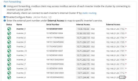
Enable/Configure Rules for Port forwarding by selecting the check box.
Enter all of the desired Ports in the right most column.
Ports must be between and 1702-1752.
38 of 73Installation and Operation Guide SOLECTRIA XGI 1500 (Rev N, 22 JUN 2022)
Figure 5-7 Port Forwarding
5.9.3 Port Forwarding, DAS Configuration
The External Access IP and respective Port settings must be configured on the third-party monitoring platform
or DAS. This will allow the DAS to query the desired inverter properly.
Static Routing
To implement Static Routing the XGI Gateway Inverter(s) will need to be configured and a static routing rule
will need to be added to the LAN.
Once implemented, inverters can easily be addressed as an Endpoint Device by a DAS or other external
device using the Inverter Cluster IP address and port 502, for example: 10.78.125.31:502. Inverter Cluster IPs
can be configured; see Section 5.11.
5.10.1 Static Routing, Configuring the Gateway Inverter
To configure Static Routing first Enable External Modbus Access by selecting the check box using the GUI
of the desired Gateway Inverter.
By default the Gateway Inverter will detect and recommend an IP/Subnet from which external devices are
allowed through the Inverter Gateway Firewall. For security purposes the user is encouraged to enter the most
restrictive value, with preference given to the specific IP address of the external device (DAS). Up to two
IP/Subnet pairs can be entered on each gateway.
39 of 73Installation and Operation Guide SOLECTRIA XGI 1500 (Rev N, 22 JUN 2022)
Figure 5-8 Enabling external Modbus access, static routing
5.10.2 Static Routing, Entering Static Routing Rule on LAN
A static routing rule can be implemented on any permanently installed device on the LAN. Most commonly this
is configured on the Internet Gateway Modem/Router or the third-party DAS (if the feature is provided).
To enter the static routing rule, the following information is required:
Destination Network:
o The Gateway Inverter Cluster IP Address (Obtained from the landing page of the GUI)
MASK: Cluster LAN mask
o Determined by the IP address within the Cluster LAN. By default this is 255.0.0.0, but can be
more restrictive if custom inverter Cluster IPs are configured.
Gateway IP: Gateway Inverter External IP Address
o Listed as Active LAN IP on the Modbus Access Configuration page, see Figure 5-8
The method of entering static routing rules varies depending on the device or operating system. For more
information work with your IT professional.
Manage Cluster IP Address
The internal Cluster IP Address are automatically assigned to each XGI inverter at the factory. If desired, the IP
address can be managed and statically assigned. Supported ranges include 10.0.021 – 10.255.255.254 &
192.168.0.21 – 192.168.0.254.
NOTICE !
Internal Cluster IPs: In most applications the internal cluster IPs are only used for communication behind the
Gateway Inverters. Exceptions include: (1) utilizing Static Routing, and (2) when no gateway inverter is
configured (this is not recommended.)
Login to the inverter using the Admin credentials and navigate to Inverter Configurations Network
Configurations Advance Network Configurations Network Cluster Configurations. Select the check
box Manage cluster IP addresses and edit the Cluster IPs as desired, see Figure 5-9.
Click Save to store the changes.
40 of 73Installation and Operation Guide SOLECTRIA XGI 1500 (Rev N, 22 JUN 2022)
Figure 5-9 Manage IP Configuration
Communication and I/O Ports
The SOLECTRIA XGI has two interchangeable Ethernet Ports. These connections are located in the right-hand
compartment within the Wire Box.
5.12.1 Weather Station Connection (Optional)
Only use weather stations that connect using Ethernet. As with all other non-inverter Ethernet devices, these
should be connected outside of the Cluster LANs.
41 of 73You can also read