XZR500ST Oxygen Analyzer User Manual - 97137 Issue 8.2 June 2022 - Process Sensing ...
←
→
Page content transcription
If your browser does not render page correctly, please read the page content below
XZR500ST
Oxygen Analyzer
  User Manual

    97137 Issue 8.2
      June 2022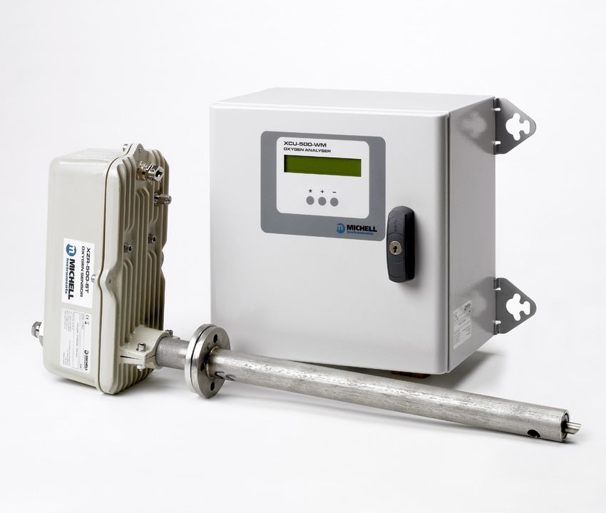
Please fill out the form(s) below for each instrument that has been purchased.

 Use this information when contacting Michell Instruments for service purposes.

Product Name

Order Code

Serial Number

Invoice Date

Installation Location

Tag Number

Product Name

Order Code

Serial Number

Invoice Date

Installation Location

Tag Number

Product Name

Order Code

Serial Number

Invoice Date

Installation Location

Tag Number
XZR500

        For Michell Instruments' contact information please go to
                           www.michell.com

                             © 2022 Michell Instruments
  This document is the property of Michell Instruments Ltd and may not be copied or
otherwise reproduced, communicated in any way to third parties, nor stored in any Data
Processing System without the express written authorization of Michell Instruments Ltd.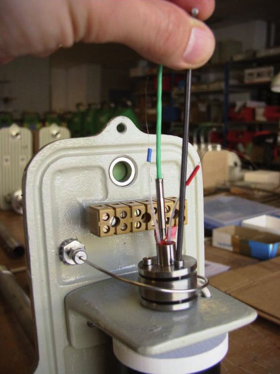
XZR500 User Manual

Contents
Safety................................................................................................................................vii
     Electrical Safety...........................................................................................................vii
     Pressure Safety............................................................................................................vii
     Temperature................................................................................................................vii
     Toxic Materials.............................................................................................................vii
     Repair and Maintenance...............................................................................................vii
     Calibration...................................................................................................................vii
     Safety Conformity........................................................................................................vii
Abbreviations..................................................................................................................... viii
Warnings........................................................................................................................... viii

1      INTRODUCTION.................................................................................................1
       1.1   System Description.............................................................................................. 1
       1.1.1    Measurement Principle................................................................................... 1
       1.1.2    Zirconia......................................................................................................... 1
       1.1.3    The MSRS..................................................................................................... 2
       1.1.4    XZR500 MSRS Assembly................................................................................. 2
       1.2   General Remarks................................................................................................. 3
       1.2.1    Sensor Head and Probe.................................................................................. 3
       1.2.2    Control Unit................................................................................................... 4
       1.3   Specifications ..................................................................................................... 6
       1.3.1    General......................................................................................................... 6
       1.3.2    Optional Equipment........................................................................................ 8
       1.3.3    Options......................................................................................................... 8

2      INSTALLATION...................................................................................................9
       2.1    General Mounting Precautions ............................................................................. 9
       2.2    Probe Mechanical Installation ........................................................................... 10
       2.3    Control Unit Mechanical Installation.................................................................... 13
       2.4    Wiring.............................................................................................................. 13
       2.4.1      Cable Specifications...................................................................................... 13
       2.4.2      Connection of the Cable (supplied) to the Control Unit.................................... 13
       2.4.2.1        Connection to the Mains......................................................................... 14
       2.4.2.2        Connection of the 0/4...20 Output........................................................... 14
       2.4.2.3        Connection of the Alarms........................................................................ 14
       2.4.3      Connection of the Cable to the Sensor Head.................................................. 14

3      OPERATION.....................................................................................................16
       3.1    Outputs............................................................................................................ 16
       3.1.1      Analog Output............................................................................................. 16
       3.1.2      Alarms........................................................................................................ 16
       3.2    Start-Up............................................................................................................ 17
       3.3    Display, Configuration and Adjustment................................................................ 18
       3.3.1      Visualization Menu [*].................................................................................. 18
       3.3.2      Set-up [ - ].................................................................................................. 21
       3.3.2.1        Access code 0.12 - quick settings............................................................ 22
       3.3.2.2        Access code 0.20 - advanced settings...................................................... 24
       3.3.3      Calibration [+]............................................................................................. 29
       3.3.3.1        Recommended Calibration Gas................................................................ 29
       3.3.3.2        Regulating the Calibration Flow Rate....................................................... 29
       3.3.3.3        Calibration Procedure............................................................................. 30

iv
   97137 Issue 8.2, June 2022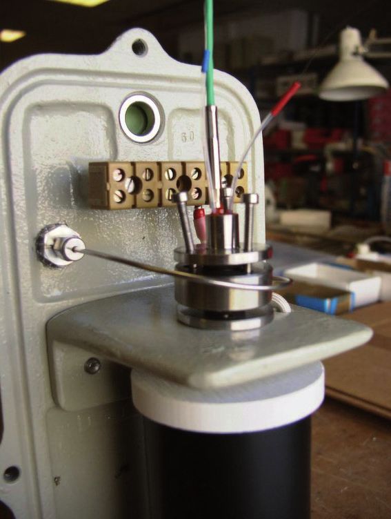
XZR500 User Manual

4   MAINTENANCE.................................................................................................34
    4.1       Preventative Maintenance - Cleaning................................................................... 34
    4.2       Replacement Of The XZR500 MSRS ................................................................... 35
    4.3       Replacement of the Furnace............................................................................... 37
    4.4       Replacement of the XZR500 Microcontroller Card................................................. 38
    4.5       Replacement of Fuses........................................................................................ 38
    4.6       Error Messages ................................................................................................ 39

5   SPARE PARTS...................................................................................................41

Figures
Figure   1            Zirconia Principle.........................................................................................1
Figure   2            The MSRS and its K Thermocouple...............................................................2
Figure   3            XR500 MSRS...............................................................................................2
Figure   4            XZR500 Sensor Head & Probe......................................................................3
Figure   5            Digital Display Panel....................................................................................4
Figure   6            Main Display...............................................................................................4
Figure   7            Control Unit ..............................................................................................5
Figure   8            Probe Installation......................................................................................10
Figure   9            Probe Head Orientation..............................................................................10
Figure   10           Flange Gasket Orientation..........................................................................11
Figure   11           Tubular Counter Flange Position.................................................................11
Figure   12           Inner Tube Orientation...............................................................................12
Figure   13           Hex Screw Locations..................................................................................14
Figure   14           Probe Wiring Diagram................................................................................15
Figure   15           Calibration Flow-Chart...............................................................................33
Figure   16           XZR500 MSRS Mounting Diagram...............................................................35
Figure   17           XZR500 Top View......................................................................................36
Figure   18           XZR500 Side View.....................................................................................36
Figure   19           XZR500 Sensor Head & Probe General Dimensions......................................50
Figure   20           Position of the Probe.................................................................................52
Figure   21           Installation of the Ejector/Heating System...................................................55
Figure   22           Enclosure for Controlling the Ejector Heating - General Wiring Diagram.........56
Figure   23           System diagram........................................................................................59
Figure   24           Timing diagram.........................................................................................59
Figure   25           Exploded analyzer view..............................................................................62
Figure   26           XZR500 Flange and Back Flange (Optional).................................................64
Figure   27           Insulators (Flange and Rear Sealing Screw).................................................64
Figure   28           Mounting Plate Dimensions........................................................................65
Figure   29           Wiring of the Second 4...20 mA Output.......................................................67

Michell Instruments		                                                                                                                v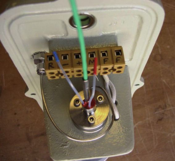
XZR500 User Manual
Tables
Table 1 Control Keys...............................................................................................5
Table 2 Maximum Temperature of Gases...................................................................7
Table 3 Cable Specifications................................................................................... 13
Table 4 Connection of the Control Unit................................................................... 13
Table 5 Access codes 0.12 & 0.20.......................................................................... 21
Table 6 Alarm Set-Point Examples.......................................................................... 23
Table 7 Fuse Replacement..................................................................................... 38
Appendices
Appendix A Technical Specifications...............................................................................43
Appendix B Configuration for the RS232 Port (Optional)..................................................45
Appendix C Calculation of CO2 .....................................................................................48
Appendix D XZR500 Sensor Head and Probe General Dimensions....................................50
Appendix E Back Flushing System (optional)..................................................................52
Appendix F Heated Flue Gas Ejection System (Optional).................................................55
Appendix G Combined Air Ejector / Back-Flushing System...............................................59
Appendix H Mounting Options.......................................................................................64
H.1 Tubular Counter Flange and Insulators...........................................64
H.2 Mounting Plate Dimensions...........................................................65
Appendix I Second 4...20 mA Output............................................................................67
Appendix J Automatic Calibration (Optional) .................................................................69
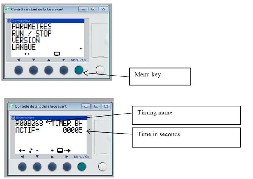
J.1 Adjusting the Sequence Parameters...............................................71
Appendix K Quality, Recycling & Warranty Information....................................................73
Appendix L Return Document & Decontamination Declaration.........................................75
vi
97137 Issue 8.2, June 2022
XZR500 User Manual

Safety

The manufacturer has designed this equipment to be safe when operated using the procedures
detailed in this manual. The user must not use this equipment for any other purpose than that
stated. Do not apply values greater than the maximum value stated.

This manual contains operating and safety instructions, which must be followed to ensure the safe
operation and to maintain the equipment in a safe condition. The safety instructions are either
warnings or cautions issued to protect the user and the equipment from injury or damage. Use
qualified personnel and good engineering practice for all procedures in this manual.

Electrical Safety

The instrument is designed to be completely safe when used with options and accessories supplied
by the manufacturer for use with the instrument. The input power supply voltage is 230 V AC or 115
V AC, 50/60 Hz. Refer to labels on instrument or calibration certificate.

Pressure Safety

DO NOT permit pressures greater than the safe working pressure to be applied to the instrument.
The specified safe working pressure, for all versions of this instrument, is 10 bar.

Temperature

Some parts of the analyzer can be at a very high temperature. DO NOT open the enclosure of the
probe during operation. Switch off the analyzer first and wait for at least 30 minutes.

Toxic Materials

The use of hazardous materials in the construction of this instrument has been minimized. During
normal operation it is not possible for the user to come into contact with any hazardous substance
which might be employed in the construction of the instrument. Care should, however, be exercised
during maintenance and the disposal of certain parts. Long exposure or breathing of the calibration
gases may be dangerous.

Repair and Maintenance

The instrument must be maintained either by the manufacturer or an accredited service agent. Refer
to www.michell.com for details of Michell Instruments’ worldwide offices contact information.

Calibration

The recommended calibration interval for the analyzer is 6 to 12 months depending on the application
in which the instrument is used.

Safety Conformity

This product carries the CE/UKCA mark and meets the requirements of relevant European safety
directives.

Michell Instruments		                                                                            vii
XZR500 User Manual

Abbreviations

      The following abbreviations are used in this manual:

      AC        alternating current
      A         Ampere
      °C        degrees Celsius
      °F        degrees Fahrenheit
      Hz        hertz
      kg        kilogram(s)
      l/hour    liters per hour
      mA        milli Ampere
      mbars     millibars
      mm        millimeter(s)
      ppm       parts per million
      T         Temperature
      V         Volt
      W         Watts

Warnings

      The following general warnings listed below are applicable to this instrument. They are
      repeated in the text in the appropriate locations.

                         Where this hazard warning symbol appears in the following
                           sections it is used to indicate areas where potentially
                               hazardous operations need to be carried out.

                        Where this symbol appears in the following sections it is used
                            to indicate areas of potential risk of electric shock.

viii
     97137 Issue 8.2, June 2022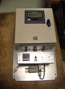
XZR500 User Manual                                                         INTRODUCTION

1       INTRODUCTION

        XZR500 Series Oxygen Analyzers are designed to measure the oxygen content in flue
        gases between 0.01 % and 25 % O2. They allow for the improvement of a boiler’s
        performance, increasing equipment service life and surveying emissions, thereby
        contributing to protecting the environment.

        XZR500 Oxygen Analyzers can be used for several applications such as monitoring
        combustion in power plants, incineration of industrial or domestic waste, incineration of
        VOC, control of processes, etc.

        Please read this manual carefully before starting up the analyzer. It is recommended
        that you go through this manual again after the first use to enable optimal use of the
        XZR500.

1.1     System Description

1.1.1   Measurement Principle

        Michell Instruments’ aim is to provide the best measurement solutions for any
        given industrial process or laboratory application. In the case of oxygen control and
        measurement we have developed a highly advanced and miniaturized oxygen sensor,
        the MSRS. This innovative sensor is at the heart of the XZR500 analyzer. A key strength
        of the MSRS is that it has a built-in metal reference, this means it can operate for very
        long periods without any requirement for re-calibration against a reference gas. As a
        result the XZR500 has very low lifetime costs compared to other oxygen analyzers.

        In addition to providing reliable and hassle free operation, the MSRS also delivers
        excellent accuracy, class-leading linearity and, due to its small size, has a superior
        response speed.

        The operating principle of the MSRS is explained in detail as follows:

1.1.2   Zirconia

        Zirconia is a solid electrolyte. At high temperatures
        it conducts oxygen ions. An electrochemical voltage
        develops between the two platinum-plated surfaces
        of the zirconia in contact with two different gaseous
        oxygen partial pressure (Pp) atmospheres. This voltage
        follows the Nernst equation, expressed as:

                    RT              Ppmeas.
          E=        4F
                            ln
                                     Ppref.

                                                               Figure 1       Zirconia Principle
        where R and F are constants

        E = Nernst voltage (V)
        T = temperature (°K)
        Pp = oxygen partial pressures

Michell Instruments		                                                                              1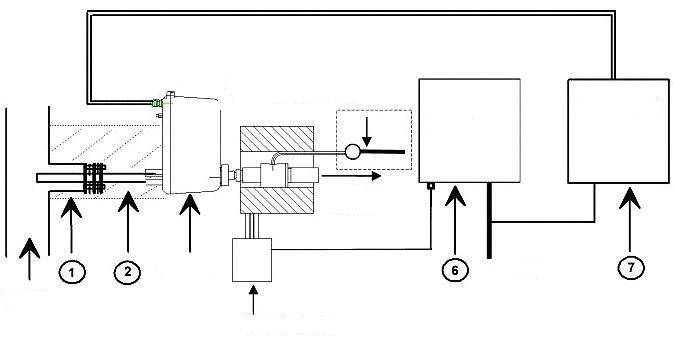
INTRODUCTION                                                        XZR500 User Manual

        By setting the oxygen reference pressure and measuring voltage E and temperature T,
        you can deduce the oxygen partial pressure you want to measure.

        The volumetric concentration (expressed here in O2 %vol.) is determined by the ratio
        between the oxygen partial pressure (Ppmeas) and the atmospheric pressure (Ptot).

                                                          Ppmeas.
                                        O2 %vol. =
                                                          Ptot.

        There is an optional ambient pressure sensor available for higher accuracy measurements.

1.1.3   The MSRS

                            Figure 2      The MSRS and its K Thermocouple

        Unlike conventional “air reference” zirconia sensors the MSRS uses the equilibrium
        status of an internal metal oxide to provide a reference. Therefore, this built-in metallic
        reference sensor does not require any reference gas.

        The MSRS is a very small cylinder, 3 mm in diameter and 10 mm long. A K thermocouple,
        placed closed to the MSRS, measures its temperature with great precision. This design
        leads to extremely high accuracy and very good resistance to thermal shocks. It also
        increases the lifetime of the sensor.

1.1.4   XZR500 MSRS Assembly

        The MSRS and its K thermocouple are placed inside an aluminum tube. The MSRS head
        is attached to an assembly plate to allow for easier field servicing, see Figure 3 below.

        1.   aluminum tube
        2.   O2 reference         wire with blue mark
        3.   O2 reference         wire with red mark
        4.   + thermocouple       wire with green mark
        5.   - thermocouple       wire with white mark

                                       Figure 3      XR500 MSRS

2
  97137 Issue 8.2, June 2022
XZR500 User Manual INTRODUCTION
1.2 General Remarks
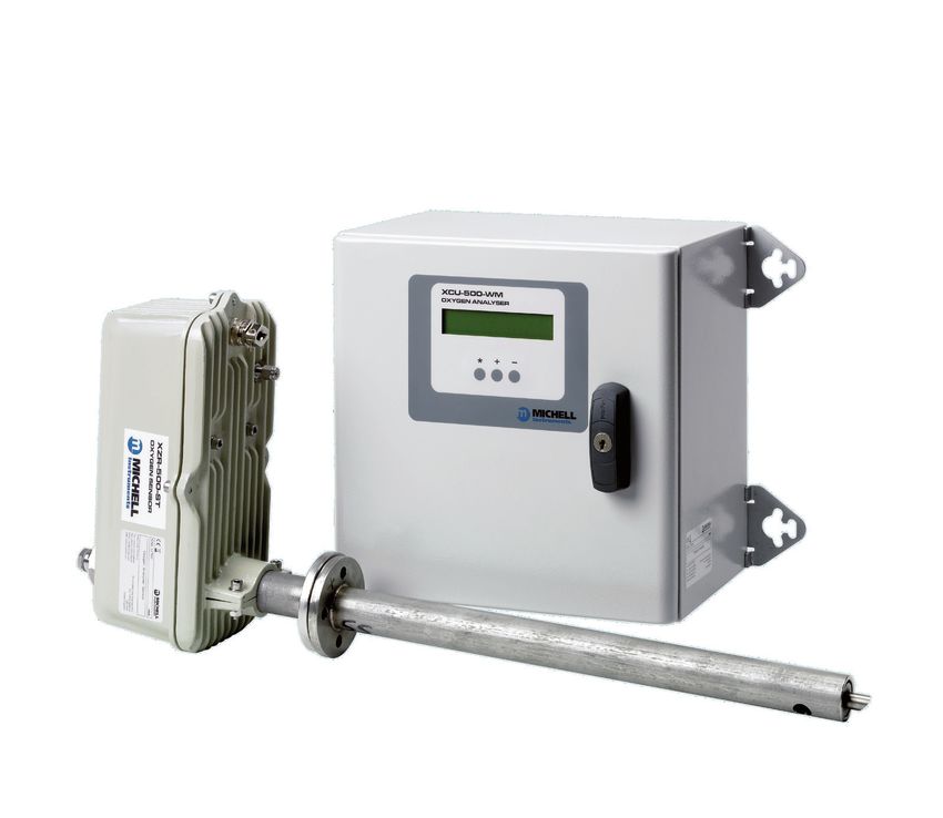
The analyzer is made up of a measurement probe and a Control Unit.
1.2.1 Sensor Head and Probe
The semi in-situ arrangement consists of the following elements:
• Sensor head, containing MSRS, sensor furnace, cable connection &
calibration port.
• Probe, comprising of an inner and outer tube to allow flow of sample from
flue to sensor.
The sample gas is returned to the flue practically unchanged in composition and
condition. This is due to the very small amount of sample required to diffuse into the
sensor furnace.
The gas flow is shown by the arrows in Figure 4 below. In this example, the stack is
vertical and the flue gas flow direction is upwards.
Using the Pitot tube effect, gases enter through the hole near the tip of the outer tube
and circulate in the space between the outer tube (25, 2) and the inner tube (23).
During this process the gases contact the sensor through diffusion. They then flow into
the inner tube and to the flue via the bevelled edge.
The tubes are fitted so that the bevelled edge of the inner tube and the holes of the
outer tube face in opposite directions.
12
17
11
15 10
1
16
3
14
13 24
19
8 18
6
4
25 2 21
5
28
29
9
27
20 22 26 23
7
1 Sensor housing 11 XZR500 connector block 20 M6 Nut for fixing XZR500 probe plate
2 Outer tube 12 SS bulkhead union for cal.gas 21 M6 washer
3 Sealing head 13 2 sealing ferrules 22 M6 lock washer
4 XZR500 furnace 14 Nut for fixing bulkhead union 23 Inner tube
5 XZR500 MSRS 15 Stainless steel plug 24 VITON 8 x 2.5 O-ring
6 Gasket for flange (x2) 16 M8 lock washer 25 Outer tube
7 Gasket for wheel 17 Cable gland 26 Locking ring
8 Inter-tubes gasket 18 M8 spacer 27 Gasket for plug
9 Gasket for sealing screw 19 CHC 6x25 screw for fixing 28 Big rear nut
XZR500 sensor attachmt plate
10 TRF 3x16 screw for connector 29 Inter-tube gasket
Figure 4 XZR500 Sensor Head & Probe
Michell Instruments 3INTRODUCTION XZR500 User Manual
The XZR500 MSRS (5) assembly is placed perpendicular to the tubing system. The
XZR500 furnace (4) and the XZR500 MSRS (5) are placed inside a cast aluminum
enclosure which is made of two parts sealed with a 5 mm diameter viton O-ring. It is
dust proof and waterproof and can be mounted outdoors. The cable gland (17) is made
of brass.
The whole set is mounted on the stack with a steel flange which is welded on the
XZR500 outer tube. Michell Instruments can provide an optional mounting kit containing
a counter flange with threaded rods (if needed please refer to Appendix G).
All the gaskets (6, 7, 8 and 9) placed on the tubes are made of carbon fiber.
A high temperature “gasket box” type device guarantees that the sealing head is airtight.
For dimensions of the measuring probe see Appendix D.
1.2.2 Control Unit
The Control Unit provides the Human Machine Interface (HMI) for the XZR500 analyzer.
It is housed in a metal case with a screen and three touch buttons to allow access to
menus. Inside there is a motherboard, a micro-controller and a display PCB. The output
signals and alarms are all accessed through the Control Unit.
Oxygen concentration is displayed on the screen as default and has one decimal
point as standard (a second decimal place can be requested as an option). Other
parameters available through the HMI are Furnace Temperature, Thermocouple Junction
Temperature, MSRS Voltage and Ambient Pressure (in mbars), if the optional pressure
sensor is ordered.
Configuration of alarms and output signals as well as calibration functions are all carried
out through the HMI of the Control Unit.
The digital display panel of the analyzer is shown in Figure 5.
* - +
XZR500
Figure 5 Digital Display Panel
O2 Concentration
xx.xx%
Figure 6 Main Display
The instrument display is divided into two lines. The upper line is the descriptive line
and the bottom line displays the measured values or the function keys.
4
97137 Issue 8.2, June 2022XZR500 User Manual INTRODUCTION
The function keys are located below the display and are used to select operations
from the main menu level, to enter sub-menu levels and to select and enter parameter
variables within those menu levels. The function key panels are shown in Figure 5 and
Table 1 describes the operation of the keys.
Key Function
[*] Enter or select key. Operation of this key from the front-page display causes
the selection menu to be displayed
[+] Value up key. Used to change the value. Access key to the Calibration menu
[-] Value down key. Used to change the value. Access key to the Set-up menu
Table 1 Control Keys
The analog output signal can be set in 0...20 mA or 4...20 mA. The scale is configurable
in the range of 0.01...25 % O2.
The system provides three alarms on relay contact: a general failure alarm and two
threshold alarms with user-configurable set-point (action high and low) and hysteresis.
Figure 7 Control Unit
Cable
The cable connecting the control unit and the probe supplies the furnace with power
and it relays the MSRS temperature and voltage measurements to the Control Unit.
The standard cable length is 6 meters long (optional, up to 100 meters).
Michell Instruments 5INTRODUCTION XZR500 User Manual
1.3 Specifications
1.3.1 General
• Microcontroller: Motorola 68HC12
• Inlet converter: analog, 16 bits resolution, 0.0015 % linearity error,
with filter and embedded calibrator
• Outlet converter: analog, 12 bits resolution, ±1 bit linearity error
• Display resolution: 0.1 % O2 (or 0.01 % on request and during
calibration)
• The 3-button keypad and digital interface allow:
Reading
Continuous display of the oxygen concentration to one decimal place (option
of second dp). Other parameters available through the HMI are Furnace
Temperature, Thermocouple Junction Temperature, MSRS Voltage and
Ambient Pressure (in mbars), if the optional pressure sensor is ordered.
Configuration
Configuring of the test gas value, activation direction of the alarms (high
or low) and hysteresis level, the fail safe value (output value sent by the
electronics in case of general failure), language (English, French or Italian),
the output analog signal, the associated scale and the factory settings. (For
other parameters see specific Appendix.)
• Output signal: 0...20 mA or 4...20 mA (user-selectable) galvanic isolation
(500 V), linear and programmable, output range can be selected between
0.01 % and 25 % O2
• Output impedance: > 1 k Ω
• Alarms: contacts are normally closed, dry and potential-free, the cutting
power is max. 10 W (up to 100 V or up to 0.5 A):
1. General failure alarm warning of furnace under temperature
(20 °C below the instruction), thermocouple separation, problems
with RAM backup after a re-set or adjustment error
2. Threshold alarms, with programmable activation direction and
hysteresis
• Consumption: 110 VA
• Ingress and impact protection:
Electronic enclosure: IP52 and IK05
Probe: IP53 and IK05
• Storage temperature: between -10 and +70 °C
6
97137 Issue 8.2, June 2022XZR500 User Manual INTRODUCTION
• Dimensions (mm):
Control Unit: 300 x 300 x 200 (w x h x d)
Sensor Head: 135 x 290 x 670 (w x h x d) (standard model)
Probe: 400, 600 or 900 mm in length, with an outer diameter of 40
mm
• Weight:
Control Unit: Approximately 7 kg
Sensor Head: Approximately 3 kg
Probe: Approximately 2...6 kg (dependant upon length & material of
construction)
• Power requirements: 230 or 115 V, -15 %/+10 %, 50/60 Hz
• Operating ambient temperature and moisture:
Temperature from 0 to 55 °C
Relative moisture from 5 % to 90 % (non-condensing)
• Maximum temperature of the sample gases (Table 2):
Model Tubing Materials Gas Properties
XZR500 /SS 304 L stainless steel Tmax = 700 °C
XZR500 /IL Inconel 600 Tmax = 1000 °C
XZR500 /HR HR160 Tmax = 1000 °C and corrosive gases
XZR500 /HC Hastelloy C2000 Tmax = 600 °C and corrosive gases
XZR500 /CC Ceramic Tmax = 1300 °C
XZR500 /HL Halar coating Tmax = 150 °C
Table 2 Maximum Temperature of Gases
• Minimum speed of the sample gases: 0.5 m/s
Michell Instruments 7INTRODUCTION XZR500 User Manual
1.3.2 Optional Equipment
• Tubular counter-flange for fixing the probe to the stack (see Appendix H)
• Flange insulation (to prevent condensation forming)
• Extra length of cable (up to 100 meters)
• Calibration and verification kit
• Back flushing system: for cleaning the probe tubes when flue gases are
very dusty (see Appendix E)
• Flue gas ejector system with heating (see Appendix F)
• Rear insulation
1.3.3 Options
• Self-calibration
• 115 V / 60 Hz power supply
• RS232 interface (see Appendix B)
1. Transmits all data straight from/to a computer terminal, i.e: O2
concentration, furnace temperature, MSRS voltage, ambient
temperature and pressure.
2. Allows the setting of test gas value and starting the analyzer
calibration sequence.
3. Allows the changing of the alarm type, level and hysteresis, the
fail safe value, setting of the furnace temperature, the upper
scale adjustment, the signal output and scale, and starting the
self cleaning.
8
97137 Issue 8.2, June 2022XZR500 User Manual INSTALLATION
2 INSTALLATION
2.1 General Mounting Precautions
• Place the probe as close as possible to the process (without breaching
the flame front).
• Prevent ambient air from entering the stack upstream or at the probe
tapping point and interfering with the measurement. Make sure all the
gaskets are placed and tightened (Figure 4), and tighten-up the SS plug
for calibration gas inlet (Figure 4 (15)).
NOTE: The stainless steel plug – or any 1/8” sealing ferrule –
should be tightened up by hand and then tightened again using a
7/16” spanner, turning only 1/8th of a turn so as not to damage
the connection.
• Avoid placing the probe near cleaning devices or elements that create
vibrations and are liable to disturb the measurement.
• Voltage should be applied to the analyzer immediately after the instrument
is fixed on the stack so that the furnace can start heating. This will avoid
condensation at cold points where dirt could aggregate and clog up the
probe tubes. For the same reason, we recommend leaving the analyzer
powered up 24 hours a day, 365 days a year.
• The part of the tubing situated between the stack and the probe head
should be very well insulated - or even heated. If necessary, Michell
Instruments can manufacture a complete insulating cover for the outside
part of the probe (optional).
NOTE:
Ceramic probes require special handling.
Please read the following note carefully.
Ceramic Probes:
Special care must be taken when handling ceramic probes due to their fragile
nature. Inspect the probes thoroughly before inserting into stack. If they
have been damaged in transit, contact your Michell office or distributor
immediately and inform them of the situation. Take photographic evidence
of the damage to the probe, and of the packaging, on the day of delivery.
On insertion ensure that the probe does not impact with the side of the orifice.
Once installed, it is not recommended to remove the probe. If removal is
unavoidable due to maintenance, then allow the probe several hours to fully
cool to ambient temperature and extract slowly.
Consideration for placement of the probe is essential. Avoid the flame front,
violently turbulent sections of the duct/flue, proximity to dampers, or where
falling refractory could strike the probe. Excessive vibrations must be avoided
as ceramic is a brittle material.
Incorrect handling or placement of the probe will invalidate the warranty.
Michell Instruments 9INSTALLATION XZR500 User Manual
2.2 Probe Mechanical Installation
e. Probe head
g. Gasket for locking ring
h. Locking ring 3 marks to indicate d. Gasket for flange
the bevelled edge
Nut
f. Inner probe tube
c. Outer tube
b. Gasket for flange
a. Tubular
counter flange
i. Rear nut
5° Gasket
j. Gasket
Bevelled edge
Horizontal line
Gas Inlet hole
Figure 8 Probe Installation
The XZR500 is simple to set-up. Follow the instructions below:
1. Weld the tubular counter-flange (a) onto the stack. Follow the orientation
shown below to ensure that the probe head is set in a vertical position.
Slope the tubular counter-flange (a) slightly (maximum 5 degrees) so
that condensed water can go back to the process. The probe is fitted
with a PN6 DN15 type flange (4 x 11 mm diameter holes, placed on
a 55 mm diameter circle). Pay special attention to the orientation and
slope especially if the counter flange/nozzle with flange is provided by
the customer.
055mm
055mm
05
5m
m
5°
Figure 9 Probe Head Orientation
10
97137 Issue 8.2, June 2022XZR500 User Manual INSTALLATION
2. Place the outer probe (c) with the flange gasket (b) according to the
drawing in Figure 8. The gas inlet hole should face the process flow.
Process flow
Gas inlet
hole
Gas inlet
hole
Process flow
Figure 10 Flange Gasket Orientation
3. Mount the probe head (e) with the flange gasket (d) on to the tubular
counter-flange (a). Secure the tubular counter flange, flange for outer
tube and flange of the probe head together by secure nuts onto four bolts
on the counter flange.
e. Probe head
d. Gasket for flange
b. Gasket for flange
a. Tubular
counter flange
Figure 11 Tubular Counter Flange Position
Michell Instruments 11INSTALLATION XZR500 User Manual
4. Place the gasket onto the inner tube (f) and insert into the probe head
(e) (see Figure 8). Make sure the bevelled edge of the inner tube tip
faces the opposite direction to the gas inlet hole on the outer tube (c) as
shown below. There are three marks on the other end of the inner tube
to indicate the orientation of the bevelled edge (see Figure 12).
c. Outer tube
Bevelled edge
f. Inner tube
Gas inlet hole
Process flow
Figure 12 Inner Tube Orientation
5. Place the locking ring (h) with the locking ring gasket (g), the rear nut
(i) and the inner tube gasket (j) accordingly on the rear of the probe
head. (See Figure 8)
6. Put insulation between process and the probe head if necessary.
If the back flush option is chosen, then the orientation
must be reversed. This is because the inner tube
becomes the inlet so any dust build up will happen in the
inner tube. When the back flush is operated, it clears the
tube more efficiently.
12
97137 Issue 8.2, June 2022XZR500 User Manual INSTALLATION
2.3 Control Unit Mechanical Installation
The Control Unit is supplied with lugs for fitting on the wall (see Figure 7).
2.4 Wiring
Only authorized personnel should open the control unit.
Take all precautionary measures to avoid accidents
related to electrostatic shocks.
2.4.1 Cable Specifications
The standard analyzer is supplied with 6 meters of cable. Longer cable lengths are
available up to 100 meters. The electrical connections are as follows:
brown
brown } 2 wires to supply the power to the furnace
green
white
(+)
(-) } 2 wires for measuring the thermocouple voltage
blue
red
(reference)
(measurement) } 2 wires for measuring the MSRS voltage
Table 3 Cable Specifications
The wires should be stripped to 8 mm at each end. There is a ground wire at one end
of the supplied cable. This end should be connected to the Control Unit.
2.4.2 Connection of the Cable (supplied) to the Control Unit
Connect the supplied cable - using the end with 7 wires (including ground wire) - as
follows:
29 30 31 32 33 34 35 36 37 38 39 40 41 42 43 44 45 46 47 48 49 50
Furnace power brown
Furnace power brown
General fault alarm
General fault alarm
(green)
(white)
(blue)
(red)
+mA Output
-mA Output
Meas. 02
Alarm 1
Alarm 1
Alarm 2
Alarm 2
Ref. 02
230 N
Vac P
Earth
+TC
-TC
NC
NC
NC
NC
NC
to the
0/4...20mA
From the sensor Output
sensor to the Mains
(furnace)
J4 Left connector: measurement
J5 Right connector: power and alarms
CABLE
(supplied)
Table 4 Connection of the Control Unit
Both the ground wire of the supplied cable and the earth wire from the mains must
be connected to the copper bar near the cable gland.
Michell Instruments 13INSTALLATION XZR500 User Manual
2.4.2.1 Connection to the Mains
Use shielded cable (2 x 1.5 mm² max.) that is terminated appropriately. Follow the
Table 4 wiring diagram (pins 48, 49 and 50).
Connect both the screen and the earth wire to the copper bar near the cable gland.
2.4.2.2 Connection of the 0/4...20 Output
We suggest that shielded cable (2 x 0.75 mm²) is used and terminated appropriately.
Follow the Table 4 wiring diagram (pins 34 and 35).
Connect the braid to the copper bar near the cable gland.
2.4.2.3 Connection of the Alarms
We suggest that shielded cable is used and terminated appropriately. Follow the Table
4 wiring diagram (pins 41...46).
Connect the screen and the earth wire to the copper bar near the cable gland.
2.4.3 Connection of the Cable to the Sensor Head
Unscrew the three hex head screws at locations shown below to open the case of the
XZR500 probe head and access the terminal block.
Figure 13 Hex Screw Locations
14
97137 Issue 8.2, June 2022XZR500 User Manual INSTALLATION
Connect the end of the cable - using the end with 6 wires - according to the Figure 14
wiring diagram.
MSRS Furnace
Green
White
Blue
Red
probe
Ref. -TC +TC M F F connector
___________
___________
___________
___________
___________
___________
Brown
Brown
Green
White
Blue
Red
Supplied Cable
Figure 14 Probe Wiring Diagram
Michell Instruments 15OPERATION XZR500 User Manual
3 OPERATION
The MSRS is a fragile element - keep the sensor free from any
shock. Any measurements that need to be done at the MSRS
terminals must be done very carefully in order to prevent
irreversible damage to the sensor.
NEVER attempt to measure the resistance between the MSRS
reference terminal and another terminal
Use a voltmeter with impedance >1000 MΩ for measuring
the voltage between the MSRS measurement and reference
terminals
3.1 Outputs
3.1.1 Analog Output
The output signal is selectable to be either 0...20 mA or 4...20 mA.
The range is selectable between 0 and 25 %.
3.1.2 Alarms
The system has 3 alarm contacts:
• 1 general failure alarm warning of furnace under temperature (20 °C
below the set temperature), thermocouple separation, problem with RAM
backup after a re-set or adjustment error.
• 2 threshold alarms, with programmable activation direction and hysteresis.
The activation of a threshold alarm can be identified when the corresponding green LED
turns off on the Control Unit.
The activation of the general fault alarm can be identified when all the three green LEDs
turn off on the Control Unit.
The contacts are normally closed, dry and potential-free. The maximum switched load
is 10 W for each contact (up to 100 V or up to 0.5 A).
16
97137 Issue 8.2, June 2022XZR500 User Manual OPERATION
3.2 Start-Up
After finishing and verifying the connections, power up the analyzer.
Oven Temperature
During warm-up, the display shows:
Low alarm /xxx.x
The measured temperature value alternates with the message "Low alarm" during one
second in every two seconds.
When the temperature is within 30 °C of the required temperature (after about 15
minutes), the system calculates the oxygen concentration and the result will appear on
the display.
O2 Concentration
Then the following default message appears:
xx.xx %
Michell Instruments 17OPERATION XZR500 User Manual
3.3 Display, Configuration and Adjustment
During configuration there is no data communication
between the Control Unit and the Sensor Head
and this could disturb the stability of the furnace
temperature. Make sure that the furnace temperature
is stable before configuration and allow the analyzer’s
temperature to stabilize after configuration.
To display the main selection menu, press and
hold the [*] Enter key until the menu appears. Your selection?
You can now select the option you need by
pressing one of the following keys: Visu * Cal + Set -
[ *] Enter key cycles displayed parameters
[-] Minus key to enter the set-up mode
[+] Plus key to enter the calibration mode
3.3.1 Visualization Menu [*]
The visualization menu displays the following parameters:
• O2 concentration
• Oven temperature in °C
• Temperature of the thermocouple cold junction in °C (ambient temperature)
• MSRS voltage
• Pressure value
Proceed as described above to enter the main selection menu. To scroll through the
parameter list use the [*] Enter key as shown below.
It is not possible to change any values in the visualization menu. To change values go
to the set-up menu.
1. From the main menu, press and hold the
[*] Enter key until the main selection Your selection?
menu appears
Visu * Cal + Set -
2. Press the [*] Enter key from the main
selection menu to show the first parameter: O2 Concentration
O2 concentration
xx.xx %
18
97137 Issue 8.2, June 2022XZR500 User Manual OPERATION
3. Press and hold the [*] Enter key again to
re-enter the main selection menu Your selection?
Visu * Cal + Set -
4. Press the [*] Enter key from the main
selection menu to show the second Oven temperature
parameter: Oven temperature
xxx.x °C
5. Press and hold the [*] Enter key to re-
enter the main selection menu Your selection?
Visu * Cal + Set -
6. Press the [*] Enter key from the
main selection menu to show the third Ambient temperature
parameter: Ambient temperature
xx.x °C
7. Press and hold the [*] Enter key to re-
enter the main selection menu Your selection?
Visu * Cal + Set -
8. Press the [*] Enter key from the main
selection menu to show the fourth Cell voltage
parameter: Cell voltage
xx.xx mV
Michell Instruments 19OPERATION XZR500 User Manual
9. Press and hold the [*] Enter key to
re-enter the main selection menu Your selection?
Visu * Cal + Set -
10. Press the [*] Enter key from the main
selection menu to show the fifth parameter: Absolute pressure
Absolute pressure
xxxx.x mBar
11. Repeating the process again will return
to the default displayed parameter: O2 O2 Concentration
concentration
xx.xx %
NOTE: If you do not press the [*] Enter key within 30 seconds, while showing
one of the parameters, the display will automatically return to the default
display of O2 concentration.
20
97137 Issue 8.2, June 2022XZR500 User Manual OPERATION
3.3.2 Set-up [ - ]
The set-up mode is used for changing system control parameters, each of which are
selected from the set-up configuration table. There are two different sets of setting
parameters. Quick settings are accessible under code 0.12, while advance settings are
accessible under access code 0.20.
Access Function Default Unit Remarks
Code Setting
Resets the system to standard configuration.
The default configuration is restored. The
current parameters will be deleted. Usually
Std config. 0.30 0.00 N/A
necessary after replacement of the micro
controller card. Do not change without
consulting factory
Test gas value 8.00 % Sets the value of the calibration gas
Sets alarm type. If value >1.00 high Alarm 1,
Type Alarm 1 2.00 N/A
if value 1.00 high Alarm 2,
Type Alarm 2 2.00
if valueOPERATION XZR500 User Manual
3.3.2.1 Access code 0.12 - quick settings
From the main menu page, press and hold the
[*] Enter key until the main selection menu Your selection?
appears.
Visu * Cal + Set -
Press the [–] (Set-up menu) from the main
selection menu to show the Access code page. Access code?
Using the [–] and [+] keys enter the 0.12 code 0.12
to access the quick settings and press the [*]
Enter key to confirm the selection.
Standard Configuration
The first page under access code 0.12 is
for restoring the factory default standard Std config. 0.30
configurations.
0.00
A standard configuration should be restored after replacing the microcontroller
card.
Consequences: All the parameters change to the default value. The analyzer
is no longer calibrated.
DO NOT change the value from 0.00 without consulting the
factory. Restoring to standard configuration will change all the
parameters of the last set-up. Make sure you note down all
parameter values before executing the operation. After re-set
the analyzer is no longer calibrated.
If a standard configuration is not necessary leave the value as 0.00 and press the [*]
Enter key to go to the next page.
If a standard configuration is necessary, enter 0.30 and press the [*] Enter key to
activate the restoring process.
Calibration gas value
This page shows the current calibration gas
value. Use the [+] and [–] keys to modify the Test gas value
value and press the [*] Enter key to confirm the
selection and move to the next parameter. 8.00
NOTE: This value is in %. For example,
8.00 equals 8 %.
22
97137 Issue 8.2, June 2022XZR500 User Manual OPERATION
Alarm 1
1. The ‘type of alarm’ screen is used to set-
up the direction for the Alarms 1 and 2 Type Alarm 1
to the values ‘High’ and ‘Low’. The ‘High’
alarm will be activated when increasing 2.00
the signal value to above the set-point
level. The ‘Low’ alarm will be activated by
decreasing the signal value to below the
set-point level.
Values higher than 1.00 indicate that the alarm type will be ‘High’. Values lower than
1.00 indicate that the alarm type will be ‘Low’. Press the [+] and [–] keys to modify
the value. Press the [*] Enter key to confirm the selection and move to the next
parameter.
2. Depending on the selection in step 1, the
next page shows High/Low set-point of High Alarm 1
Alarm 1. Press the [+] and [–] keys to
modify the set-point and press the [*] 2.00
Enter key to confirm the selection and
move to the next parameter.
NOTE: If the alarm is set as Low alarm this page will display ‘Low Alarm 1’
accordingly
NOTE: This set-point value is in %. For example, 2.00 equals 2 %. The value
can be set between 0 and 200 %.
Alarm set-point = (alarm level/max value of the scale) x 100
Example 1: Calculation: The set value has to be 60
Selected range is 1-1,000 ppm. %= (600 ppm*100) as 600 ppm represents 60 %
The desired alarm is at 600 ppm. /1000 ppm = 60 of the range
Example 2: Calculation: The set value has to be 6 as
Selected range is 10-10,000 ppm. %= (600 ppm*100) 600 ppm represents 6 % of
The desired alarm is at 600 ppm. /10,000 ppm = 6 the range
Example 3:
Calculation: The set value has to be 0.24
Selected range is 1 ppm to 25 %
% = (600 ppm*100) as 600 ppm represents 0.24
logarithmic. The desired alarm is
/250,000 ppm = 0.24 % of the range
at 600 ppm.
Table 6 Alarm Set-Point Examples
Alarm 2
To configure Alarm 2, repeat steps 1 and 2 as shown in Alarm 1.
Michell Instruments 23OPERATION XZR500 User Manual
Alarm hysteresis
This page shows the value for the relay hysteresis
that is expressed in percentage oxygen. Press Relay hysteresis
the [+] and [–] keys to adjust the value. Press
the [*] Enter key to confirm the selection and 0.10
move to the next parameter.
Fail safe value
This page shows, in percentage, the fail-safe
value of the measurement range. This is the Fail safe value
percentage value that the 4...20 mA output will
go to under fault conditions. E.g. 100.00 means 0.00
the output will be 20mA (100 %) under fault
conditions.
Press the [+] and [–] keys to adjust the value.
Press the [*] Enter key to confirm the selection.
The Access code page will appear.
3.3.2.2 Access code 0.20 - advanced settings
At the Access code page, use the [–] and [+]
keys to enter the 0.20 code to access the Access code?
advance settings and press the [*] Enter key to
confirm the selection. 0.20
Oven temperature set-point
This first page under access code 0.20 is used
to set the temperature of the sensor oven. Oven temp set pt
CAUTION: Do not change the value without 700.00
consulting the factory.
Press the [*] Enter key to move to the next
parameter.
Languages
English, French or Italian can be selected as the
display language. There are separate pages for English ?
each language.
No * Yes -
Press the [*] Enter key to stay with the current
language in use
Press the [–] key to change to the chosen French ?
language
Non * Oui -
Italiano ?
No * Si -
24
97137 Issue 8.2, June 2022XZR500 User Manual OPERATION
Offset compensation MSRS cold junction
This page shows the offset value for
compensation of the MSRS thermocouple cold Offset room temperature
junction. The value is factory pre-set and may
vary for individual analyzers. 3.00
CAUTION: Do not change the value without
consulting the factory.
Press the [*] Enter key to move to the next
parameter.
Span compensation MSRS cold junction
This page shows the span value for compensation
of the MSRS thermocouple cold junction. Room temp. grad.
The value is factory pre-set and may vary for
individual analyzers. 10.00
CAUTION: Do not change the value without
consulting the factory.
Press the [*] Enter key to move to the next
parameter.
High Adjust
This page shows the ‘High adjust’ function that
allows the user to adjust the reading around 21 High adjust
% oxygen. The value is factory pre-set and may
vary for individual analyzers. 2.00
NOTE: The value is factory pre-set. It can
be changed when different calibration is
required.
After a calibration, let the air circulate
for approximately 15 minutes, and then
adjust this value to give a 21 % oxygen
reading. If the calibration is done with air,
set the value to 0.00.
The equation to calculate the high adjust is:
HA = ((20.9 - O2reading) /O2 reading) * 100
e.g. If the analyzer display is 20.4 %
HA = ((20.9 - 20.4) / 20.4) * 100 = 2.5
Press the [+] and [–] keys to adjust the value.
Press the [*] Enter key to confirm the selection
and move to the next parameter.
Michell Instruments 25OPERATION XZR500 User Manual
Output Signal
This page shows the available current ranges
for the signal output. Enter 0.00 for 0...20 mA 0 or 4...20 mA
and 4.00 for 4...20 mA. Press the [+] and [–]
keys to adjust the value. Press the [*] Enter 4.00
key to confirm the selection and move to the
next parameter.
Measurement range – lower limit
This page shows the selected lower limit of the
measurement range. Press the [+] and [–] keys Rec. range low
to adjust the value. Press the [*] Enter key
to confirm the selection and move to the next 0.01
parameter.
NOTE: This value is in %. For example,
0.01 equals 0.01 % O2.
Measurement range – upper limit
This page shows the selected upper limit of the
measurement range. Press the [+] and [–] keys Rec. range up
to adjust the value. Press the [*] Enter key
to confirm the selection and move to the next 10.00
parameter.
NOTE: This value is in %. For example,
10.00 equals 10 % O2.
CO2 factor
This page is used to enter the CO2 maximum
theoretical value of the fuel gas for CO2 CO2 factor
calculation. Press the [+] and [–] keys to adjust
the value. Press the [*] Enter key to confirm 0.00
the selection and move to the next parameter.
(See Appendix C)
26
97137 Issue 8.2, June 2022XZR500 User Manual OPERATION
Gr value
This value is for factory settings only.
Gr
10.00
CAUTION: Do not change the value without
consulting the factory.
Press the [*] Enter key to move to the next
parameter.
Ti value
This value is for factory settings only.
Ti
10.00
CAUTION: Do not change the value without
consulting the factory.
Press the [*] Enter key to move to the next
parameter.
Offset pressure
This page displays the offset pressure. The value
is factory pre-set and may vary for individual Offset pressure
analyzers.
8.00
CAUTION: Do not change the value without
consulting the factory.
Press the [*] Enter key to move to the next
parameter.
Absolute pressure
This page displays the absolute pressure.
The value is factory pre-set and may vary for Abs. pressure
individual analyzers.
11.00
CAUTION: Do not change the value without
consulting the factory.
Press the [*] Enter key to move to the next
parameter.
Michell Instruments 27OPERATION XZR500 User Manual
Cell self-cleaning
This function allows the analyzer to self-clean
the sensor cell. The cleaning process lasts for Cleaning cell
one hour. The furnace is heated to 780 °C in
order to clean itself and the MSRS. Remove the 0.00
inner probe tube to make the self-cleaning more
efficient.
NOTE: During self-cleaning, the output
signal will be locked at the fail-safe value
If cell cleaning is not required, leave the value
at 0.00 and press the [*] Enter key to skip this
procedure and go back to the default display.
If cell cleaning is required, press the [+] and [–]
keys to adjust the value to 0.10 and press the
[*] Enter key to start the process. The following
messages will appear:
Temperature Oven
Low alarm
The process can be stopped by pressing and Cleaning cell
holding the [*] Enter key or it will stop
automatically after the above 60 minute process End of control?
is completed. Once the cleaning process is
finished the furnace will start to cool down.
Cleaning cell
After about 10 minutes the temperature will
return to the set temperature. 60 min
Cleaning cell
cooling
Cleaning cell
10 min
Temperature Oven
xxx.x °C
28
97137 Issue 8.2, June 2022XZR500 User Manual OPERATION
3.3.3 Calibration [+]
The XZR500 has been designed for simple operation. The calibration procedure is
extremely easy and can be performed within minutes. The analyzer is self-adjusting
during calibration. There are only a few steps that need to be carried out for the actual
calibration procedure.
3.3.3.1 Recommended Calibration Gas
NOTE: Please make sure that only gas of a known composition is used for
calibration of the XZR500. The gas cylinder must be certified as to the exact
composition of the calibration gas.
Michell recommends the following calibration gas concentrations that can be ordered
from your analyzer vendor.
• 1G Calibration Kit with one gas cylinder (nitrogen with 8 % oxygen
concentration)
• 2G Calibration Kit with two gas cylinders (nitrogen with 8 % oxygen
concentration for calibration and nitrogen with 2 % oxygen concentration
for verification)
CALIBRATION GAS UNCERTAINTY:
Observe the uncertainties of the calibration gas when
calculating the overall analyzer uncertainty. Any uncertainty
of the oxygen content of the calibration gas may introduce
considerable error in the calibration of the analyzer.
NOTE: Prior to calibration, make sure that the ‘Test gas value’
in the access code 0.12 of the analyzer menu is the same as
the calibration gas value.
3.3.3.2 Regulating the Calibration Flow Rate
In order to perform the calibration it is recommended to arrange a temporary connection
with a regulator and isolation valve located at the calibration gas inlet on the analyzer.
Make sure the connection is as short as possible. A regulator and isolation valve are
supplied in the calibration kit.
Connect the calibration kit or your test gas cylinder to the calibration gas inlet (Figure
4 (12)). Use 1/8” tube and fitting. NOTE: Ensure a flow of 7 l/hour (±2 l/hour)
(0.12 to 0.18 l/min).
NOTE: Tighten up the stainless steel locking nut by hand and then tighten again
using a 7/16" spanner, for 1/8th turn so as not to damage the connection.
NOTE: During calibration the output signal is frozen at the last value measured
before the beginning of the calibration procedure.
Michell Instruments 29OPERATION XZR500 User Manual
3.3.3.3 Calibration Procedure
Follow Sections 3.3.3.1 and 3.3.3.2 to connect the calibration gas to the analyzer (8 %
oxygen bottle, if 1G or 2G is ordered). Do not switch on the calibration gas flow at this
time.
1. From the main page, press and hold the
[*] (Enter key) until the main selection Your selection?
menu appears.
Visu * Cal + Set -
2. Press the [+] key from the main selection
menu to enter the calibration mode. The Test gas value
first page displays the ‘Test gas value’.
Make sure that the displayed value is the 8.00
same as the calibration gas.
NOTE: This value is in %. For
example, 8.00 equals 8 %.
If the displayed value is not the same value
as the calibration gas, exit the calibration
mode from next page (‘Inject gas’) and
then go to ‘Test gas value’ under ‘Set-
up menu’ Access code 0.12 to adjust it.
(Please refer to details in Section 3.3.2.1)
Press the [*] (Enter key) to move to the
next page.
3. This page shows the calibration start
command. Inject gas
[*] – Starts the calibration process (go to Yes* No -
step 4)
[–] key – Cancels the calibration process
and exits the calibration mode. If the ‘Test
gas value’ needs to be modified, then go
to ‘Test gas value’ under ‘Set-up menu’
Access code 0.12 to adjust it.
NOTE: Once the calibration process
starts (after pressing the [*] key),
the 4...20 mA output will be frozen
from this step until the end of the
purge procedure and will show the
last measured value.
4. Open the test gas cylinder to introduce
the gas into the analyzer. Adjust the flow
to the recommended level of 7 l/hour (±2
l/hour) and ensure that the flow is stable.
Higher or lower flow rates could affect
the accuracy of the calibration as well as
further measurements.
30
97137 Issue 8.2, June 2022You can also read