VERTEX Lite Collar User's Manual - Version: 1.3 - Vectronic Aerospace
←
→
Page content transcription
If your browser does not render page correctly, please read the page content below
VERTEX Lite Collar

   User's Manual

          Version: 1.3

      Last Change: 16.06.2022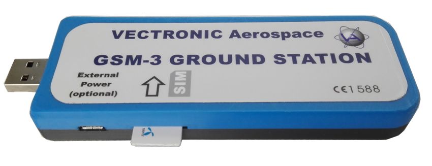
VERTEX Lite Collar
User Manual
© 2022 VECTRONIC Aerospace GmbH

All rights reserved. No parts of this work may be reproduced in any form or by any means - graphic, electronic, or
mechanical, including photocopying, recording, taping, or information storage and retrieval systems - without the
written permission of the publisher.

Products that are referred to in this document may be either trademarks and/or registered trademarks of the
respective owners. The publisher and the author make no claim to these trademarks.

While every precaution has been taken in the preparation of this document, the publisher and the author assume no
responsibility for errors or omissions, or for damages resulting from the use of information contained in this
document or from the use of programs and source code that may accompany it. In no event shall the publisher and
the author be liable for any loss of profit or any other commercial damage caused or alleged to have been caused
directly or indirectly by this document.

                             Marcel Butz               24.06.2016

                             Chris Samek              03.07.2019

                            Nicola Gadow              03.07.2019

                            Robert Schulte 03.07.2019
Document Change Record
Contents               4

Table of Contents

   1                 ...............................................................................................................7
         Product overview
   2     Fast guide to ...............................................................................................................8
                        deploy the collar
   3                  ...............................................................................................................9
         The Vertex Lite    collar system
       3.1 The Collar...................................................................................................................... 9

       3.2 GPS Receiver
                 ...................................................................................................................... 10

       3.3 VHF Beacon
                 ...................................................................................................................... 11

       3.4 Mortality......................................................................................................................
                      Sensor                                                                                                               12

       3.5 Activity Sensor       (Acceleration)
                    ...................................................................................................................... 12

       3.6 Drop Off...................................................................................................................... 13

       3.7 Communication       options
                ...................................................................................................................... 14

           3.7.1        Globalstar Communication
                                    ...................................................................................................... 14

           3.7.2        Iridium Communication
                                   ...................................................................................................... 15

           3.7.3        GSM Communication
                                ...................................................................................................... 16

       3.8 Software...................................................................................................................... 18

       3.9 Data Format
                  ...................................................................................................................... 18

           3.9.1        List of files and
                                      ......................................................................................................
                                             extensions used                                                                                 19

   4                ...............................................................................................................20
         System Set-up
       4.1 Installation   of the user-software GPS Plus X
                     ...................................................................................................................... 21

       4.2 Collar Registration
                   ...................................................................................................................... 21

       4.3 Registration    of Communication Devices
                   ...................................................................................................................... 22

   5     Direct Collar...............................................................................................................26
                        Communication
Contents                 5

    5.1 USB Bluetooth       Stick
               ...................................................................................................................... 26

    5.2 USB Remote      Stick
              ...................................................................................................................... 27

        5.2.1       Remote Stick
                              ......................................................................................................
                                  Collar Contact                                                                                     28

        5.2.2       Testing several
                               ......................................................................................................
                                      collars                                                                                         29

    5.3 Collar Main    Tree
                ...................................................................................................................... 29

        5.3.1       Information ...................................................................................................... 30

             5.3.1.1         Telemetry
                                ........................................................................................................... 31

             5.3.1.2         GPS   Monitor
                               ........................................................................................................... 34

             5.3.1.3         Info...........................................................................................................
                                   File                                                                                                      35

        5.3.2       Configuration
                                ...................................................................................................... 38

             5.3.2.1         User  Configuration
                               ........................................................................................................... 38

             5.3.2.2         Setting   the time
                               ........................................................................................................... 42

             5.3.2.3         Firmware       Upload
                                ........................................................................................................... 43

        5.3.3       Schedules ...................................................................................................... 44

             5.3.3.1         GPS   schedule
                               ........................................................................................................... 45

             5.3.3.2         VHF   Beacon Schedule
                               ........................................................................................................... 48

             5.3.3.3         VHF Beacon & GPS Beacon Schedule Files
                               ........................................................................................................... 49
                             Upload
        5.3.4       Collected Data
                               ...................................................................................................... 49

             5.3.4.1         Position
                               ........................................................................................................... 52

             5.3.4.2         Activity
                                ........................................................................................................... 56

             5.3.4.3         Mortality
                               ........................................................................................................... 58

6                ...............................................................................................................59
      Remote Collar   (Communication)
    6.1 Remote......................................................................................................................
               User Configuration                                                                                                    60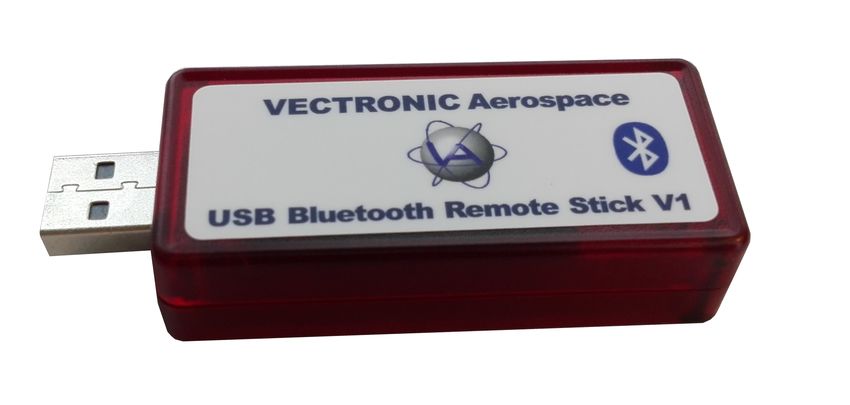
Contents               6

       6.2 Remote......................................................................................................................
                  GPS Schedule                                                                                                          63

       6.3 Remote......................................................................................................................
                  Beacon Schedule                                                                                                       63

 7                   ...............................................................................................................64
         Calculate Collar     Lifetime
 8                    ...............................................................................................................66
         Test the collar
 9                   ...............................................................................................................66
         Attach the collar     to the animal
10                    ...............................................................................................................67
         Battery options
11       Changing of ...............................................................................................................69
                      battery pack
     11.1 Oval Collar
                 ...................................................................................................................... 69

     11.2 Round Collar,     standard battery pack
                 ...................................................................................................................... 70

     11.3 Round Collar,     curved battery pack
                 ...................................................................................................................... 71

12       The Vertex Lite collar with integrated UHF
         ID-Tag      ...............................................................................................................73

13       Specification...............................................................................................................74
     13.1 Environmental      specification for the collar
                 ...................................................................................................................... 74

     13.2 Declarations    of Conformity
                 ...................................................................................................................... 75

     13.3 Certificates
                   ...................................................................................................................... 77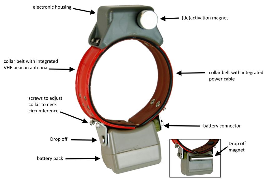
Product overview      7

1   Product overview
    The VERTEX Lite Collar generates GPS, mortality and activity data. It sends regular
    GPS and mortality updates via GSM / Globalstar / Iridium communication.

    Most important features:

     Unlimited GPS localizations per day

     3-axis accelerometer to measure activity

     User definable Beacon and GPS settings

     On board flash memory

     Drop Off (on demand)

     24/7 mortality observation and notification

     Ambient temperature data

     Any Battery 1C- 7D

     Field replaceable Batteries

    Communication options:

         Globalstar (One-way communication: enables data download)

         Iridium (Two-way communication: enables data download and upload of new
         commands and schedules)

         GSM (Two-way communication: enables data download and upload of new
         commands and schedules)

     Bluetooth Communication for on-site Data and Configuration management

    The VERTEX Lite Collars can also host an UHF ID Tag to be used in interaction studies
    in combination with a VERTEX Plus collar.

    All data is stored on the flash memory onboard the collar. GPS locations, temperature
    and event data are sent using either Globalstar / Iridium / GSM communication. After
    retrieval of the collar, data can be downloaded using the USB Remote Stick (wireless
    data communication with a few meters range).

                                                             © 2022 VECTRONIC Aerospace GmbH
Product overview       8

    Globalstar collars can be reconfigured with the USB Remote Stick, whereas Iridium and
    GSM collars can also be reconfigured remotely using the two-way communication:

           GPS schedule and settings

           Beacon schedule and settings

           Mortality period

           Iridium / GSM settings

2   Fast guide to deploy the collar
    The collars come thoroughly tested and fully programmed according to your instructions.
    Nevertheless we recommend to setup your GPS Plus X (software) system beforehand,
    check the programmed settings and test the collars:

    1. Make yourself familiar with the collar [(de)activation magnet should be attached]

    2. Setup your GPS Plus X software system (for further information please refer to the
       GPS Plus X software manual)

    3. Register the collars

    4. Check / change the settings (using the USB Remote Stick / USB Bluetooth Stick)

    5. Check Drop Off configuration and lifetime (please refer to GPS Plus Drop Off
       Manager or Info Files provided with the collar)

    6. Make a lifetime calculation (optional)

    7. Test the collars

        7.1 Remove the (de)activation magnet (not the Drop Off magnet!)

        7.2 Place them preferably outdoors with clear view to the sky (Do not place the
            collars too tightly as their signals might interfere and affect the testing)

        7.3 Listen for the VHF beacon signal (Check settings for frequency and pattern
            types beforehand)

        7.4 Wait for incoming messages (Check for expected time frames first, plan your
            testing to include several data transmission windows)

        7.5 Process incoming data and check signal quality etc.

                                                                © 2022 VECTRONIC Aerospace GmbH
Fast guide to deploy the collar    9

          7.6 (GSM / Iridium: send reconfiguration commands remotely)

          7.7 Deactivate them by reattaching the magnet

        Do not trigger the Drop Off! It can only be used once!

      8. Check and optionally alter the settings to field configuration

      9. Deploy the collar (NOTE: remove all magnets and cut the overhanging belting to
         minimize the risk to injure or handicap the animal)

      The steps of this list will be explained in more detail in the following chapters.

3     The Vertex Lite collar system
      The VERTEX Lite Collar uses a two housing design, one electronic and one battery unit.
      The VHF beacon antenna is integrated into the belt. There are different collar designs,
      housings and battery sizes to fit it to each species.

      follow the links to the subtopics explaining the collar and its system:

      The collar

      GPS Receiver

      VHF Beacon

      Mortality Sensor

      Communication options

      Software

      Data Format

3.1   The Collar
      The VERTEX Lite Collar consists of the following components:

                                                                      © 2022 VECTRONIC Aerospace GmbH
The Vertex Lite collar system   10

                                      Figure 1: VERTEX Lite Collar

3.2   GPS Receiver
      The collar contains a standard GPS receiver with an accuracy within 8 - 15 meters as
      mean. The actual accuracy depends on many factors such as terrain, satellite reception
      and time to conduct a fix (GPS position). Most fixes will be far more accurate.

      A GPS schedule defines when GPS positions will be recorded. Programming of the
      GPS schedule is very flexible and easy.

      Once activated the receiver listens for satellite data and collects ephemerides data to
      conduct a GPS location. The maximum listening period is 180s but it will stop listening
      before that if

         a) it receives a validated fix of highest quality

         b) it gets several decent quality signals

         c) it gets no satellite connection at all

      Each GPS position is stored with following data:

                                                                     © 2022 VECTRONIC Aerospace GmbH
The Vertex Lite collar system 11
- UTC (universal time coordinated) date and time
- GPS coordinates (Latitude, Longitude and Height)
- Dilution of Precision (DOP) and navigation status as quality information as well as
number of satellites used for positioning.
GPS data can be exported via the user software GPS Plus X to ASCII, Spreadsheet,
DBase, GPS Exchange, Google Earth and BioTelemetry eXchange format. You can
easily import the data into Google Earth via kml.file to visualise GPS positions.
3.3 VHF Beacon
The collar is equipped with a powerful VHF beacon. The VHF Beacon transmits a signal
on Very High Frequency. It allows you to track the collar even if satellite or GSM
communication is down. The VHF Beacon is set for a certain range of frequencies and
you are able to change it within this range using GPS Plus X. You can program when the
VHF Beacon is on and also its signal pattern. The VERTEX Lite has three distinct signal
modes, the Standard Pattern, the Mortality Pattern, and the Emergency Pattern. There is
a backup battery for the beacon to ensure you do not lose your collar due to low battery
issues. The Mortality Pattern is active when a mortality event has been recorded
(Mortality Sensor). The default setting can be seen below but you are able to change the
Pulse Length and also Loop Length meaning the cycle in which the signal is repeated.
Figure 2: Beacon patterns (default setting): Standard Pattern, Mortality Pattern, Emergency
Pattern
The changes can be made in the GPS Plus X software:
Devices Remote Stick VERTEX Lite Configuration User
Configuration
Devices USB Bluetooth VERTEX Lite Configuration
© 2022 VECTRONIC Aerospace GmbHThe Vertex Lite collar system 12
User Configuration
3.4 Mortality Sensor
The mortality sensor measures the activity of the animal. If no movement (activity) is
detected for a user-defined period (e.g. 24 hours), a mortality event is triggered. The
mortality period is user-definable and can be set up to 140 hours. When a mortality
event is detected, the collar:
- Switches the VHF Beacon pattern to the Mortality Mode
- Sends out a mortality event message via Globalstar / Iridium / GSM
communication
- Conducts unscheduled GPS fixes each 30 minutes for six hours before it returns
to the programmed schedule
- Sends messages according to set communication patterns
The collar will end the mortality mode if the sensor registers repetitive activity for roughly
20 minutes.
NOTE: The mortality period should be adapted to the behavior of the collared animal so
you get no false events (e.g. lions with a very long passive phase should get a longer
mortality period as for example roe deer with a distinct but short activity pattern). The
default setting is 24h which has been used successfully in a variety of studies.
3.5 Activity Sensor (Acceleration)
The VERTEX Lite Collar is equipped with a Basic Activity sensor. The data are stored
in the on board flash memory. The sensor records average data every 300 seconds.
You can analyze relative activity based on right-left, up-down and forward- backward
movement.
© 2022 VECTRONIC Aerospace GmbHThe Vertex Lite collar system 13
Figure 3: Directions of the three activity axes
3.6 Drop Off
Drop Offs allow retrieving the collar without having to recapture the animal.
There are two optional Drop Offs available:
- Timer-controlled Drop Off: The collar is released after a pre-defined period of time
(relative mode, e.g. 100 weeks) or at a pre-defined date and time (absolute mode, e.g.
01 April 2017). The lifetime of the Drop Off is up to five years after production. The
countdown in relative mode starts after removing the Drop Off magnet.
- Radio-and-timer-controlled Drop Off: The collar is released on demand by UHF
radio signal. To trigger the release a UHF Handheld Terminal Version 5 or higher or a
Drop Off Release Transmitter is needed. The maximum distance is about 500 m (For
more information please refer to the Drop Off Release Transmitter manual). Additional
timer control (relative or absolute mode) functions as backup. The lifetime of this Drop
Off is up to 4 years after production.
Figure 4: Drop Off magnet for standby mode
© 2022 VECTRONIC Aerospace GmbHThe Vertex Lite collar system 14
Figure 5: Drop Off release sites, magnet removed
3.7 Communication options
The VERTEX Lite Collar is available as Iridium, Globalstar or GSM version. Follow the
link to your chosen configuration for information about the respective communication
system.
Iridium
Globalstar
GSM
3.7.1 Globalstar Communication
Globalstar offers a one-way communication, which means you receive GPS and
mortality data, transmitted by the collar. The system provides a broad, but space and
time restricted coverage network.
Figure 6: Globalstar Coverage 2015
© 2022 VECTRONIC Aerospace GmbHThe Vertex Lite collar system 15
Each position data is sent by the collar (1-2 Fix per message with minimum pause of
30min between each message). Data is sent out several times to increase transmission
probability but data reception is not confirmed by the satellites. The satellite sends its
data to a base station on ground which forwards it via web to our system. It is possible
that transmissions are blocked (e.g. thick canopy, bad angle towards sky etc.) and do
not reach the satellites and thereby you. Most often the data will get through and to our
system from which your GPS Plus X software will automatically download the data. You
can also get the data as email forwarding when the Http download is unsuitable for
whatever reason. You can get the full dataset by downloading it with the USB Remote
stick after collar retrieval.
NOTE: You can set a skip count to exclude some fixes from the data satellite
transmission pool to receive fewer messages and thereby extend the collar lifetime (e.g.
skip count 2 means sending only every second fix, all data remains stored on the collar
too). Please keep in mind that you cannot alter the settings once the collar is deployed.
A skip count could potentially drastically reduce the collar messages you receive up to
getting no data (e.g. high GPS skip count in a very unsuitable habitat such as dense
forest). For further information please contact our customer service.
3.7.2 Iridium Communication
Iridium offers a two-way communication, meaning you receive GPS data from the collar
and can send new commands and schedules remotely to the collar. The Iridium system
consists of 141 satellites with global coverage for 24/7.
Figure 7: Iridium 24h worldwide satellite coverage
You can download and upload schedules and configurations remotely. Due to the two-
way communication, the collar knows which data have been received by the satellite and
which data need to be resent again. That means you will get all data though data
packages come in later.
For transmitting the data, the collar needs a clear view to the sky. The number of fixes
defines the message size and thereby transmission time.
© 2022 VECTRONIC Aerospace GmbHThe Vertex Lite collar system 16
How it works:
The system uses 3 message blocks wherein the first block can contain 1-4 GPS fixes,
the second block, an additional 8 at most and the third and last block, an additional 6. In
total, 18 fixes (in one big message) can be transmitted in one transmission window. The
remaining space within a block will be filled with placeholder data, so the message won't
get smaller if you choose less than 4 (1-3), 12 (5-11), 18 (13-17).
Please note that the collar “listens” for incoming commands only when it is sending out
data, meaning you have distinct communication windows based on the schedule used
and transmission made (e.g. hourly fixes with 4 fixes a message result in one message
every 4 hours). Data are sent to our GPS Plus X main server and provided to your GPS
Plus X software for HTTP download or email forwarding / reception.
NOTE: It highly depends on species and terrain how many fixes the collar should
transmit in one message. In most cases we recommend to start with 4 fixes per
message (default settings) and to increase the number after deployment when you see
data is incoming regularly. An unsuitable setting (e.g. 18 fixes / message in dense
forest) could result in high rate of failed transmissions or in worst case in loosing contact
to the collar.
NOTE: You can set a skip count to exclude some fixes from the data satellite
transmission pool to receive fewer messages and thereby extend the battery lifetime
(e.g. skip count 2 means sending only every third fix, all data will be stored in the collar
too). A skip count reduces the collar messages you receive (High GPS skip count in a
very unsuitable habitat such as dense forest may result in losing contact with the collar).
3.7.3 GSM Communication
GSM is using the SMS service of mobile phone providers. The GSM communication is
a two-way communication, meaning you receive GPS data from the collar and can send
new commands and schedules remotely to the collar. GPS and mortality data will be
sent automatically via SMS to the defined phone number. If you wish to send new
commands or schedules remotely, please contact our customer service. It is only
possible to communicate with the collar within GSM provider coverage.
© 2022 VECTRONIC Aerospace GmbHThe Vertex Lite collar system 17
Figure 8: GSM Communication
For collar usage within Europe we provide GSM collars with VECTRONIC SIM chips
so you do not have to take care about provider administration. VECTRONIC SIM chips
are soldered in the electronic housing and highly reliable in all kinds of environmental
conditions (heat, cold, humidity, vibrations, shock).
How it works:
One message transmitted via GSM/GPRS contains 8 GPS positions per default.
Messages will be sent to VECTRONIC ground-station and from there downloaded via
HTTP to GPS Plus X software. All GPS Data, irrespective of transmitting, will be stored
in the non-volatile on-board-memory. Data not transmitted via GSM can be downloaded
via UHF radio link (if available) or via USB Remote Stick after the collar has been
retrieved.
For collar usage in Africa, Asia or North- and South America, you may choose your own
mobile phone provider and provide Micro SIM cards on your own. Here, message
transmitted via GSM contains 7 GPS positions per default. It is recommended having
your own GSM Ground station if you using your GSM collars with your own SIM cards.
© 2022 VECTRONIC Aerospace GmbHThe Vertex Lite collar system 18
Figure 9: GSM Ground Station
NOTE: If no communication can be established between the GSM network and the
collar or the GSM ground station, the GSM provider will retry to send the data. Data in
the provider's memory are subject to a validity period. If no contact has been
established within this period (usually 2-3 days, but depending on the provider's
conditions), the data stored by the provider will be deleted without delivery. For this
reason, make sure that your ground station is switched on at all times to allow the data
to reach you within the validity period. If a newly sent GPS schedule is not delivered
within the validity period, resend the schedule to make sure that the collar has received
the new schedule from the GSM network. If you have questions please do not hesitate to
ask our customer service.
3.8 Software
All VECTRONIC collars are managed with our free software GPS Plus X which can be
downloaded from our homepage (www.vectronic-aerospace.com). It is also on the user-
CD which initially accompanied the collars.
The auto-installer includes an Installation Wizard which will guide you through the
installation and setup.
For more information refer to System Set-up.
3.9 Data Format
All data is stored internally in binary format and can be exported as ASCII, Spreadsheet,
DBase, and BioTelemetry eXchange format. GPS data can also be exported as GPS
Exchange and Google Earth files.
- GPS position information: No, Collar ID, UTC date and time, LMT date and
time, origin, SCTS date and time, ECEF X,Y and Z, latitude/longitude/height,
DOP, 3D Error, number of the used satellites, Satellite ID (Sat No), Carrier to
Noise (C/No [dBHz]), battery voltage, mortality status, temperature and activity
- Temperature: Temperature data are stored and transmitted with the GPS
position data.
© 2022 VECTRONIC Aerospace GmbHThe Vertex Lite collar system 19
- Mortality information: Date and time of a mortality event based on the activity
of the animal. The GPS Plus X software stores the received mortality message in
the data base.
- Activity: records averaged data every 300 seconds on 3-axis (X, Y, Z). So,
you can analyze relative activity based on right- left, up- down and forward-
backward movement. Activity data can be downloaded after collar retrieval.
(Format: adf. or adf3.)
3.9.1 List of files and extensions used
Download files
.GDF GPS Data File Binary coded GPS fix data from the collar including
main battery voltage, VHF beacon battery voltage, and
temperature. The file name consists of the collar
number and the time stamp of the file creation coded
as “yyyymmddhhmmss”.
Export files
.GDF GPS Data File Binary coded GPS fix data from the collar including
main battery voltage, VHF beacon battery voltage, and
temperature. The file name consists of the collar
number and the time stamp of the file creation coded
as “yyyymmddhhmmss”.
.TXT ASCII Visually readable equidistant table, compatible to con-
ventional text editors and spreadsheets
.CSV Spreadsheet Computer readable table, compatible to conventional
text editors and spreadsheets
.DBF DBase Table Database format, compatible to conventional spread-
sheets and most text editors
GPS Exchange
.GPX File for data exchange with GPS devices
Format
.KML KML Google Earth file to display tracks, points of interest…
.KMZ KMZ Zipped Google Earth file
© 2022 VECTRONIC Aerospace GmbHThe Vertex Lite collar system 20
BioTelemetry
.BTX VECTRONIC-defined XML-format
eXchange
.GDX GPS Data eXchange Is an XML format defined by VECTRONIC Aerospace,
which will make it easier to exchange acquired data
over system boundaries. It is an internal format of GPS
Plus X and can also be used as import format.
.ADF 2-axis Activity Data File
.ADF3 3-axis Activity Data File
Upload files
.vbsf Beacon Schedule File VHF beacon schedule of the Survey collar
.vgsf GPS Schedule File GPS schedule of the Survey collar
Hardware information files
.CCF Collar Configuration contains the configuration (schedules, communication
File configuration, activity mode) of the collar
.bin Collar Firmware File contains firmware for Survey collars
.key Collar Key File contains a key for one collar, needed to register the
collar in the GPS Plus X and to manage its data
.txt Collar Info File contains all information on the collar configuration
4 System Set-up
All VECTRONIC collars come completely programmed according to your specifications.
You can change the configuration yourself with the GPS Plus X user software and the
Communication Device (USB remote Stick, USB Bluetooth Stick).
This section will guide you through all steps for getting started whereas you will
find a more detailed description for all features in the GPS Plus X software Manual.
© 2022 VECTRONIC Aerospace GmbHSystem Set-up 21
Firstly: Installation of the user-software GPS Plus X
Secondly: Collar Registration
Thirdly: Registration of the Communcation Device (USB Remote Stick / USB Bluetooth
Stick)
4.1 Installation of the user-software GPS Plus X
The Installation wizard will guide you through the process of installing GPS Plus X. You
can install the software from the User-CD (auto-run or manual from the folder / software /
GPS Plus X) or download the latest version from our website: www.vectronic-
aerospace.com.
The installation procedure will ask you for a destination directory and suggest a default
directory. You can now decide whether you want to install one of the following software
packages (list might vary with program versions):
User Interface: Collar communication and configuration
Data Storage Service: Data management, visualization and export
Data Collector Service: Data reception and distribution
Color Selector: Tool to select a color for the belt of your collar
TeamViewerQS VAS: Tool for remote desktop support
GPS Plus X Manual: integrated Manual
By default, GPS Plus X will be configured to run on a single computer. Please refer to
the GPS Plus X software manual for further details on GPS Plus X network set-up.
4.2 Collar Registration
To be able to configure the collars and to process data and messages with the GPS Plus
X software, you need to register the collars. The keys for each collar will be provided with
the User-CD which comes included with the collars.
For registering the collar, please go to the Configuration tree in GPS Plus X and
select Collars
© 2022 VECTRONIC Aerospace GmbHSystem Set-up 22
Figure 10: Collar Properties Editor
In the appearing window “Collar List”, press to add a new collar to the list. After
clicking on the button, the Collar Properties Editor appears. To register a collar, click
. An open file dialog will open and you can select the collar registration key for
the collar (to be found in the folder Resources\Collar and Drop Off Keys).
If you add the details before registering the collar, the registration status of the collar will
be invalid. After registration, the entry of the corresponding collar will change from invalid
to valid. For more information on collar registration, refer to the GPS Plus X Manual.
After you have registered the collar, you will be able to communicate with the collar using
the USB Device.
4.3 Registration of Communication Devices
To be able to configure the collars and to process data and messages with the GPS
Plus X software, please connect either the USB Remote Stick or the USB Bluetooth
© 2022 VECTRONIC Aerospace GmbHSystem Set-up 23
Stick to your PC while GPS Plus X is open. When you plug in the USB Device for the
first time, you need to register it. A window will appear to inform you that this device has
not been registered yet (see Figure below). It will give you a Device Description and the
possibility to choose a Display Name.
Figure 11: USB Remote Stick registration
Click on after you have typed in a name which allows you to recognize your
USB Device easily.
After you have registered the USB Device, it will appear in Configuration Local
Settings Device Registration.
USB Remote Stick:
Clicking on the Remote Stick symbol in the Devices tree, the USB Remote Stick
Properties frame will open.
© 2022 VECTRONIC Aerospace GmbHSystem Set-up 24
Figure 12: USB Remote Stick Properties
In this frame, you can see all the details of the Remote Stick, change the Display Name
and upload the new firmware by clicking on in the Firmware Upload tab (if a
newer version than the recent one is available).
Once you have registered the collar and Remote Stick you can start managing your
collar.
NOTE: The Driver of the Remote Stick should be found automatically. If the installation
does not work automatically you can find the driver (as executable) on the User-CD,
folder Resources/VECTRONIC Tools and Drivers/USB Driver installer/ USB To Collar
© 2022 VECTRONIC Aerospace GmbHSystem Set-up 25
Interface Driver Setup.exe)
USB Bluetooth Stick:
If the Bluetooth Stick does not show up, refer to USB Bluetooth Stick for information
about driver setup.
If you click on the USB Bluetooth Stick itself the property frame will open. Here you
can rename your device or upload the latest firmware version.
Figure 13: USB Bluetooth Stick Properties
© 2022 VECTRONIC Aerospace GmbHDirect Collar Communication 26
5 Direct Collar Communication
VERTEX Lite Collars can be accessed via USB Remote Stick or via USB Bluetooth
Stick.
Figure 14: left: USB Remote Stick; right: USB Bluetooth Stick
Combined with the GPS Plus X software, these are tools to upload configurations,
schedules and to download measurement data or show collar status information. You
need to make the configurations while one of the USB devices is attached to your
computer and the collar is in a range of a few meters. You are able to communicate with
several collars simultaneously and configure them parallel as well.
After you set-up your system you are able to communicate with the collar.
5.1 USB Bluetooth Stick
If you update your GPS Plus X software, the following frame will appear. Click install to
be able to use the USB Bluetooth Stick.
Figure 15: USB Bluetooth Stick Driver installation
© 2022 VECTRONIC Aerospace GmbHDirect Collar Communication 27
You can find the USB Bluetooth Stick under Devices USB Bluetooth Stick. If
you remove the magnet of your VERTEX Lite collar it will appear as a subnode of the
Bluetooth Stick. Now you can change Collar Configurations and Schedules and access
Information and Collar Data. Refer to Collar Main Tree for more information.
Figure 16: Device list: USB Bluetooth Stick
5.2 USB Remote Stick
You can find the USB Remote Stick under Devices Remote Stick. It shows two
options ( Radio Monitor and Device Search) whereas only the latter is important
for the first steps in collar communication.
Figure 17: USB Remote Stick Device Search frame
© 2022 VECTRONIC Aerospace GmbHDirect Collar Communication 28
The “Radio Monitor” feature is discussed in chapter The VERTEX Lite Collar as UHF ID
Tag.
In the node “Device Search” you can search for collars. Per default you search for any
devices in range (“Any Device”). You can also search for specific device types. To do
that, select a Device Type. If you want to search for a specific collar ID, please enable
Specific Device ID and select the ID of your collar. Click on , attach the
magnet to your device within the next 10 seconds and detach it after one second (As it
is described in Collar Contact (general)). A list of all devices found will appear.
Figure 18: USB Remote Stick Device Search frame
Once ensured that the devices work and can be contacted by the software, collar
communication and reconfiguration can be started.
5.2.1 Remote Stick Collar Contact
To configure the collar, make sure that the magnet is detached from the collar so that it
is able to receive configurations and send data. Whenever you click on a node in the
Devices tree (Information, Configuration, Schedules or Collected data), a notification
message will appear. In this message, you are requested to attach the magnet to the
collar and detach it after one second. You can abort the connecting process by clicking
the corresponding button or the ESC button on your keyboard.
Figure 19: Notification window which appears when you send out a command of any kind.
© 2022 VECTRONIC Aerospace GmbHDirect Collar Communication 29
It sometimes happens that the communication cannot be established, resulting in the
display of different error messages. Most often it will be enough to redo it. The
communication works best when there is a clear path between collar and USB Remote
Stick without obstacles which might interfere with the signals.
Recommendation: A simple trick to speed up the process is to place the magnet
upside-down on the connection port of the collar while working with it instead of
reattaching it securely with the Velcro tape each time.
5.2.2 Testing several collars
Most features offer you the option to read out / upload a schedule / parameter /
configuration to a specific collar or any collars in range. Using the latter option you can
check and reconfigure your collars in a row without much in-between handiwork
involved. Please note that it works for collars of one kind only.
Figure 20: Command destination
Using the “Any Collar” option, the command is internally (invisibly) altered so it can be
received and processed by any fitting collar (e.g. no collar ID involved). You will have to
press “apply”, “send” for each collar anew but do not have to move within the
configuration tree.
5.3 Collar Main Tree
Devices Remote Stick VERTEX Lite
Devices USB Bluetooth Stick VERTEX Lite
The Collar Main Tree gives you an overview on what can be down- and uploaded to and
from your collar and informs you about current settings.
© 2022 VECTRONIC Aerospace GmbHDirect Collar Communication 30
Figure 21: Collar Main Tree (VERTEX Lite)
The first node (Information) contains what it says, information about hardware and the
actual settings of the collar. It also enables testing its basic functionality.
The second node (Configuration) includes all user configurations for the collar and is,
with the third node (Schedules), where you can define and upload VHF and GPS
schedules, the most important one.
The fourth node (Collected Data) gives you the option to download data once you
retrieve the collar after its deployment.
5.3.1 Information
Devices Remote Stick VERTEX Lite Information
Devices USB Bluetooth Stick VERTEX Lite Information
Shows the actual hardware and programming settings of the collar and its functionality.
© 2022 VECTRONIC Aerospace GmbHDirect Collar Communication 31
Telemetry
GPS Monitor
Info File
5.3.1.1 Telemetry
Devices Remote Stick VERTEX Lite Information Telemetry
Devices USB Bluetooth Stick VERTEX Lite Information
Telemetry
The Telemetry window gives an overview about all hardware and software settings of the
collar. It shows the actual programming with no option to change it here. That is done (as
far as the options can be altered) in the node Configuration
© 2022 VECTRONIC Aerospace GmbHDirect Collar Communication 32
Figure 22: Collar Telemetry
System:
Collar shows Production Number, Production Date, Printed Circuit
© 2022 VECTRONIC Aerospace GmbHDirect Collar Communication 33
Board (PCB) Type and Collar ID.
Time shows the collar time in UTC and the UTC correction set for the
collar
Firmware shows information about the collar software: Bootloader and
Firmware information. Internal or service related information only
Internal Sensors shows the Main Voltage and the ambient temperature of the
included mortality sensor. The voltage is an important value to
estimate collar status as described in Position
Bluetooth Module:
Firmware Version shows Firmware Version of the Bluetooth Module in the collar
Firmware Date shows the date of the Bluetooth Module Firmware
Serial Number shows Serial Number of Bluetooth module
Memory:
External Flash Erase Time
shows time when external flash memory gets erased
Reset Counter: Internal use only (debug)
IRQ Counter: Internal use only (debug)
Link Registers: Internal use only (debug)
Sensors:
GPS shows information about the GPS Mode (internal usage only),
GPS Max Fix Time in seconds, GPS Fix Count (number of fixes
collected so far) and the GPS skip Count. The latter meaning to
put only selected fixes into the transmission data (e.g. every
second fix) and leave the rest for USB wireless data download
only.
Acceleration shows acceleration mode (basic)
Mortality shows the Period of the mortality sensor: the Default Period
which was set by VECTRONIC Aerospace and the User Period
which is user definable
Activity Activity Data Page Counter: counter to save activity data value
(in pages)
Communication:
Radio shows information about the Transmit Frequency, Receive
Frequency and Transmit Power of the collar
© 2022 VECTRONIC Aerospace GmbHDirect Collar Communication 34
Globalstar shows the Globalstar Mode, the amount of Globalstar attempts
and the ESN number
Iridium shows the Fixes per Message (user-definable) and IMEI number
of the collar (potentially needed in collar registration)
GSM mode, destination number, and the reception delay which
defines the delay until the GSM modem starts to send data
Beacon:
Beacon Frequency shows the frequency of the VHF beacon: the Default Frequency
which was set by VECTRONIC Aerospace and the User defined
Frequency. Furthermore, the values of the Beacon Min
Frequency and the Beacon Max Frequency are shown which
define in what range you are able to alter the VHF frequency
Beacon Power shows the VHF Beacon output Power.
Patterns shows information about the Standard Pattern as well as the
Mortality Pattern and the Low Battery Pattern of the VHF
beacon. The patterns include the Default Pattern which was set
by VECTRONIC Aerospace and the User Pattern if it is
configured. For the Low Battery Pattern you can define 'Start
Time', 'Cycle Period' and 'On Duration'.
Sensor Communication:
Repetition Interval defines how often the collar transmits its UHF ID
Proximity Transmitter shows if its on / off, transmit frequency, and transmit power
5.3.1.2 GPS Monitor
Devices Remote Stick VERTEX Lite Information GPS
Monitor
Devices USB Bluetooth Stick VERTEX Lite Information
GPS Monitor
The GPS monitor function allows a user to check the GPS receiver. There are two
options in this frame, GPS Warmstart and a GPS Coldstart. Both commands should
only be used for diagnostics and outside of buildings with open view to the sky.
© 2022 VECTRONIC Aerospace GmbHDirect Collar Communication 35
GPS Warmstart: This button will initiate a Warmstart of the collar. The GPS receiver
will use the Ephemerides and other data already stored in the collar (flash memory,
remains there for roughly 2hours) and only complete them with actual satellite data.
Depending on what is already stored, it can be fast or take some time. You can abort
the Warmstart by changing the node.
GPS Coldstart: The command is quite similar to the GPS Warmstart command. The
GPS receiver will skip its potentially stored ephemerides and download every available
data from the GPS satellites anew. It will take much longer to acquire a GPS location.
A GPS Coldstart is necessary if you changed the battery pack of your collar or if the
collar was inactive for a few weeks / months.
Figure 23: VERTEX Lite GPS Monitor after fix has been obtained
5.3.1.3 Info File
Devices Remote Stick VERTEX Lite Information Info File
Devices USB Bluetooth Stick VERTEX Lite Information
Info File
The collar info file includes all information on the collar configuration. It can be saved as
.TXT file or printed directly. It contains technical information of the collar as well as the
schedules. For the GPS as well as for the VHF beacon you can see the Default
Schedule and the User Defined Schedule. For the GPS as well as for the VHF beacon,
© 2022 VECTRONIC Aerospace GmbHDirect Collar Communication 36
you can see which schedule is used at the moment. Every schedule is shown in a
version which can be easily read and in the .XML format which is machine readable. An
example of an Info File of the VERTEX Lite is given in in the following table.
Recommendation: Create and save a new Info-Sheet whenever you have the collar at
hand and did any changes, especially before deployments.
© 2022 VECTRONIC Aerospace GmbHDirect Collar Communication 37
Figure 24: VERTEX Lite Iridium Info File
© 2022 VECTRONIC Aerospace GmbHDirect Collar Communication 38
5.3.2 Configuration
Devices Remote Stick VERTEX Lite Configuration
Devices USB Bluetooth Stick VERTEX Lite Configuration
In the Configuration node you can change all user-definable configurations of your collar.
Figure 25: Configuration node
Please refer to following subtopics of the Configuration Node:
User Configuration
Setting the time
Firmware Upload
5.3.2.1 User Configuration
Devices Remote Stick VERTEX Lite Configuration User
Configuration
Devices USB Bluetooth Stick VERTEX Lite Configuration
User Configuration
In this frame you can change the user-definable configurations. The actual configurations
can be seen in the collar's Telemetry and Info File. Faulty entries (e.g. faulty UTC
correction) will automatically be reset back to the factory settings defined by
VECTRONIC Aerospace.
When configuring different settings, a small window will appear whenever marking a
parameter you like to change. In this window, you will get the information which values
you can put there (Min value and Max value). This window appears in the User
© 2022 VECTRONIC Aerospace GmbHDirect Collar Communication 39
Configuration frame for every value you can configure.
Figure 26: Window with Min and Max value for the Beacon Frequency
You can define the following parameters:
System
UTC correction the collars use the UTC (Universal Time Coordinated) time
which is also used by the GPS satellite system. It differs to
your LMT (Local Mean Time). To give an example: LMT in
Germany is +2 hours to UTC, UTC correction: +2 hours. You
can set the UTC Correction in GPS Plus X and the collar will
then translate your in LMT programmed schedule internally.
Recommendation: Stick to either way (UTC correction or
UTC schedules) for all collars and document it carefully. This
helps to prevent confusion especially if you ask us to do
some changes.
Sensors
GPS Skip Count The GPS skip count refers to the satellite communication
enabling you to set a number of GPS location which will be
conducted and stored but are not added to the transmission
pool. (Example: a Globalstar collar with 2 fixes a day and
skip count 1, will send only one data message with 1
location per day).
Mortality Period Here you can set a time span using the up- and down
arrows. If the activity values remain under the set threshold
(64 within a 0-255 range, changeable by VECTRONIC) for
this time span, the animal is assumed to be dead and a
mortality event is triggered. The default value is 24h with
have been successfully used in many studies.
NOTE: Please consider which values might reflect animal
behavior at best. A short period might lead to false alarms
as the animal is only resting.
© 2022 VECTRONIC Aerospace GmbHDirect Collar Communication 40
Communication
Iridium The Iridium Mode (1-18) defines the number of fixes per
Iridium message. Please check Iridium Communication for
information about message set-up and size.
Recommendation: Mode 4
Globalstar Choose one out of 3 modes: [0] Disabled, [1] 1 Position per
Message, [2] 2 Positions per Message
GSM The GSM Mode defines number of fixes per SMS.
Recommendation: 8 fixes per message with VAS SIM
chips
7 fixes per message with SIM cards
from your own provider
You can change the destination address of all incoming
messages. By default it will be the number of VECTRONIC
ground station. If you are using your own ground station your
own mobile number is setup here.
You can configure the Reception Delay which depends on
the providers delay. The GSM module in the collar will be
booked in the network for additional time to receive
messages.
Beacon
Beacon Frequency Choose the frequency of your VHF beacon simply by typing
it into the field. You can only select frequency values
between the minimum and maximum value.
NOTE: Signal strength is best with the primarily set value
(hardware dependent), signal strength will slightly decrease
at the rim.
Beacon Power Recommendation: Stick to the default value of 10dBm as
it offers the optimum balance between signal strength and
energy consumption. Please contact our customer service if
you have questions.
© 2022 VECTRONIC Aerospace GmbHDirect Collar Communication 41
Beacon Mortality Mode This defines whether at a mortality event the VHF should
switch to be always on (24/7) or remain schedule controlled
(e.g. short window only). The Default setting is: Always on
Beacon Patterns In this frame you can configure the VHF beacon pattern for
both the Standard Mode and the Mortality Mode active
during a mortality event. You can set the pulse length in
milliseconds (ms) and the Loop Length in ms. The “pulse
Type” is for internal usage only and can’t be changed by the
user.
NOTE: The default settings have been successfully used in
many studies. Changes will affect battery consumption.
Figure 27: VERTEX Lite User Configuration
© 2022 VECTRONIC Aerospace GmbHDirect Collar Communication 42
After you have provided your changes in the configuration, you can choose to send the
new configuration only to the selected collar or to any collar by setting up the Destination
on the left side of the frame. Press to send the settings to the specific collars.
Press to reload the configuration from the actual chosen collar. Pressing the
button , all settings in the collar except the schedules are deleted.
Afterwards, the default settings defined by VECTRONIC Aerospace are applied.
5.3.2.2 Setting the time
Devices Remote Stick VERTEX Lite Configuration Time
Devices USB Bluetooth Stick VERTEX Lite Configuration
Time
To set the time in the collar, make sure that the USB Device is attached to your PC, click
on the Time frame in the Configuration node, attach the magnet to your collar within 10
seconds and detach the magnet from the collar.
Two times are displayed, the Current Collar Time [UTC] and the PC Time. The frame
also displays the Computer UTC Correction. The New Collar Time [UTC] is by default
given as the PC Time calculated from the PC UTC correction and the PC’s current time.
If there are differences between PC time and the time you want to set in the collar, use
the up- and down arrows and the calendar function or type in the new time. After you
have provided your changes in the time, you can choose to send the new configuration
only to the selected collar or to all collars found in the Device Search by setting up the
Destination on the left side of the frame. Press to send the new time to the
collar / to the collars. With you can reload the configuration from the collar.
NOTE: With each successful GPS fix, the collar time is automatically adjusted to the
correct UTC time. UTC correction will be only applied for schedules and time of the day
settings. Also, UTC correction cannot be enabled by sending the local mean time to the
collar.
© 2022 VECTRONIC Aerospace GmbHDirect Collar Communication 43
Figure 28: Set Time Frame
5.3.2.3 Firmware Upload
Devices Remote Stick VERTEX Lite Configuration
Firmware Upload
Devices USB Bluetooth Stick VERTEX Lite Configuration
Firmware Upload
A Firmware update is only necessary if you experience problems with the current collar
firmware or need a feature only available in a newer version than the present one. In this
case, get the appropriate file from VECTRONIC Aerospace. Select the update (.bin) file
with . Afterwards, you can see that some information appears in the window. You
can check information on Device Model, File Type, Version (the firmware version you
are going to upload to the collar) and the Version Attributes. Send the upgrade to the
collar with . The upload will be verified automatically while it is progressing.
© 2022 VECTRONIC Aerospace GmbHDirect Collar Communication 44
Figure 29: Collar Firmware Upload frame
5.3.3 Schedules
Devices Remote Stick VERTEX Lite Schedules
Devices USB Bluetooth Stick VERTEX Lite Schedules
Schedules, either VHF or GPS, define when the respective sensor is on, meaning the
VHF Beacon is broadcasting and the GPS receiver is conducting GPS fixes. Both
require battery power and some serious thought should be given to the settings before
deployment.
Figure 30: Schedule creation window
The schedule creation window shows all options around collar creation and is more or
less identical for the GPS as well as the VHF schedule builder. They differ in the rule
formats which are described in the following chapters.
© 2022 VECTRONIC Aerospace GmbHDirect Collar Communication 45
Load schedule from collar (either GPS and VHF schedule)
Upload created schedule to collars ( )
Erases the collar schedule
Clears the tool window to start schedule builder anew
Loads a previously saved schedule
Saves a created schedule for later usage and control
Prints out the listed rules
Schedule builder tool: add a new rule
Schedule builder tool: delete selected rule
NOTE: Please keep in mind that the VERTEX Lite Globalstar collars can’t be
reconfigured remotely once deployed.
5.3.3.1 GPS schedule
Devices Remote Stick VERTEX Lite Schedules GPS
Devices USB Bluetooth Stick VERTEX Lite GPS
A GPS schedule consists of one or more rules specifying the date and time when the
collar will do GPS fixes. Each schedule consist of a varying set of rules each consisting
of:
Start Date: the date when the rule should start
End Date: the date when the rule should end
Period Length: the length of the period in which the Sequence for GPS
recording is repeated.
Sequence: The sequence is the length of time between GPS fixes in a
© 2022 VECTRONIC Aerospace GmbHDirect Collar Communication 46
given period. Here you can define: Offset – it defines the time
span between the start of the period and the recording of the
first GPS position; Duration – period in which the GPS
positions will be recorded with the Fix Rate repetition; Fix Rate
– GPS position recording repetition rate.
NOTE: You can only take GPS fixes within the time span of the
period. This way, the sum of offset and duration must be
smaller than the value of the defined period length. If you wish to
take only 1 GPS fix per sequence, the fix rate can equal the
duration value. If you have already two position recordings in
one sequence, you can delete the other sequence in the rule
editor.
You can use up to 292 rules within one schedule and get as complex as you want (rules
for all biological- and physical seasons, planned field operation, different study or
monitoring questions etc.).
NOTE: Iridium: Field studies have shown that the transmittal of 8 fixes per day in Mode4
– 4 fixes per message) has the best energy consumption / transmittal probability ratio.
Transmittal of more fixes per day will work as well but might result in a higher degree of
unsuccessful transmission attempts. Data will reach you at some point but may be
delayed due to missed transmissions.
Recommendation: For safety reasons you should define at least one schedule starting
on 01.01.2000. If the collar's time is reset for any reason, the timer will start at this date
and will attempt to take one fix per week until another schedule starts or until the clock is
set to the correct UTC time by a successful GPS fix.
After changing the default rules to the user defined rules, you can choose if you like to
send the new schedule only to the selected collar or to all collars found in the Device
Search by setting up the Destination on the left side of the frame.
If you want to create a new schedule the first time (only the default schedule exists in the
collar), a notification window will appear when selecting the GPS schedule frame.
© 2022 VECTRONIC Aerospace GmbHYou can also read