Welding Dictionary MIG/MAG - www.ewm-group.comen/ - EWM AG
←
→
Page content transcription
If your browser does not render page correctly, please read the page content below
Welding Dictionary
MIG/MAG

                     www.ewm-group.com/en/
MIG/MAG Welding Dictionary

                                 TABLE OF CONTENTS
                                 1.   Foreword                             4
                                 2.   The procedure                        4
                                 2.1 General information                   4
                                 2.2 Current type                          5
                                 3. 	Filler metals and
                                      auxiliary materials                 5
                                 3.1 Wire electrode types                 5
                                 3.2 Technical delivery conditions
                                      for wire electrodes and
                                      flux cored wire electrodes           7
                                 3.3 Shielding gases                       8
                                 3.4 Weld metal properties                11
                                 4.   Edge preparation                    11
                                 4.1 Groove shapes                        11
                                 4.2 Applying the fusion faces            11
                                 4.3 Weld pool backing                    12
                                 4.4 Purging                              13
                                 5.   Welding machines                    13
                                 5.1 Power sources                        14
                                 5.2 Wire feeders                         17
                                 5.3 Hose package and welding torch       18
                                 5.4 Control                              19
                                 6.   Material transfer during
                                      MIG/MAG welding                     21
                                 6.1 Arc ranges                           21
                                 6.2 Short arc                            21
                                 6.3 CO2 arc process (long arc)           22
                                 6.4 Spray arc                            22
                                 6.5 Transitional arc                     23
                                 6.6 Pulsed arc                           23
                                 6.7 Special forms of material transfer   24
                                 7.   Setting welding parameters          25
                                 7.1 Setting on conventional
                                      welding machines                    25
                                 7.2 Synergetic settings
                                      for welding processes               26
                                 7.3 Stabilisation/control
                                      of MIG/MAG processes                27

2   www.ewm-group.com/en/
MIG/MAG
8.    Carrying out welding                 29   12.4	Welding fillet welds with
8.1   Arc ignition                         29          deep penetration on unalloyed
                                                       and low-alloy steel                   52
8.2   Torch guidance                       30
                                                12.5	Welding with constant
8.3   Ending the welding process           30
                                                       penetration and constant
8.4   Welding parameters                   30          power on unalloyed,
8.5   New procedures and processes         34          low-alloy and high-alloy steel        54
      a) The pulsed arc welding                 12.6	Welding using 100% CO2 on
		procedure                                34          unalloyed and low-alloy steel         55
      b) The EWM forceArc/forceArc puls         12.7	Welding full-penetration fillet
		 welding processes                       35          welds on unalloyed, low-alloy
      c) The coldArc XQ/coldArc puls XQ                and high-alloy steel                  56
		 welding processes                       36   12.8	Positional welding without using
      d) The rootArc XQ/rootArc puls XQ                the “Christmas tree” technique
		 welding processes                       36          on unalloyed, low-alloy and
                                                       high-alloy steel                      58
      e) The superPuls welding process     37
                                                12.9	Welding and brazing of unalloyed,
      f ) Positionweld                     37          low-alloy and high-alloy steel thin
      g) The wiredArc welding process      37          sheet metal and galvanised
      h) The acArc puls XQ                             sheet metal                           60
		 welding process                         37   12.10	Welding filler passes and cover
      i) The MIG/MAG tandem                            passes of high-alloy steel            62
		 welding process                         38   12.11 Welding of aluminium and
8.6 Mechanisation options                  39          aluminium alloys                      64
9.    Occupational safety                  39   12.12	Positional welding of aluminium
                                                       and aluminium alloys without use
10. Characteristics of various materials   41
                                                       of the “Christmas tree” technique     65
10.1 Unalloyed and low-alloy steels        42
                                                12.13 Welding aluminium lap welds            66
10.2 High-alloy steels and
                                                12.14 Welding aluminium fillet welds         67
      nickel-based alloys                  43
                                                12.15 Surfacing                              68
10.3 Aluminium and aluminium alloys        44
                                                13. Literature                               70
10.4 Other materials                       45
                                                       Imprint                               70
11. Application of MIG/MAG welding         45
11.1 Production branches                   45
11.2 Application examples                  46
12. Welding processes                      47
12.1 Overview                              47
12.2	Root welding of unalloyed and
      low-alloy steel                      48
12.3 Welding filler passes and
      cover passes in unalloyed and
      low-alloy steel                      50

                                                                                                  3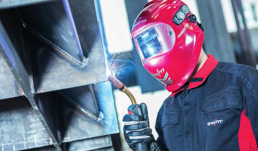
MIG/MAG Welding Dictionary
1. Foreword little effort. This brochure explains the specific
characteristics of the procedure and provides
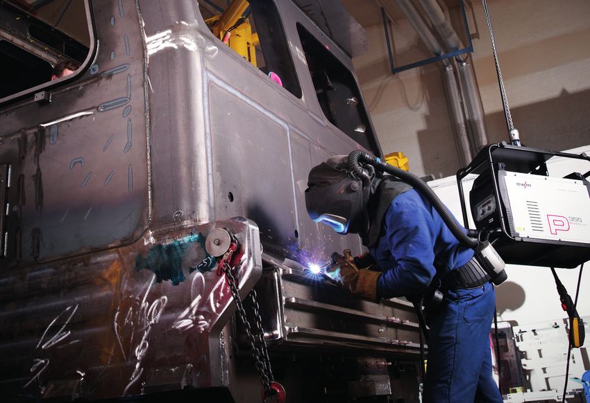
MIG/MAG welding (Figure 1) is one of the more
information on its appropriate application.
recent arc welding procedures. It originated
in the USA, where it was first used in 1948.
It arrived in Europe shortly afterwards. MIG/ 2. The procedure
MAG welding initially used inert gases such
2.1 General information
as helium and argon, which only contained
small amounts of active constituents (e.g. As defined in EN 14610, in Europe the valid
oxygen). The procedure was therefore generic term for all arc welding procedures
shortened to S.I.G.M.A. welding (Shielded where a wire electrode is melted using
Inert Gas Metal Arc). In Russia, from 1953 on, shielding gas is “gas-shielded metal-arc
with carbon dioxide (CO2) an active gas was welding” (process no. 13). The generic term
used for welding instead of expensive, inert formerly used in Germany was metal gas
gases. This was possible because high-alloy shielded arc welding. The standard explains
wire electrodes were now also available. They the procedure as follows: “An arc burns
compensate for the greater burn-off during between the workpiece and the melting
the hotter active gas welding and ensure wire electrode”. Depending on the type of
material quality. shielding gas used, it is further subdivided
into metal inert gas welding (MIG), process
MIG/MAG welding is very popular today in
no. 131, if inert gases (e.g. argon, helium) are
almost all metal processing branches, from
used, and metal active gas welding (MAG),
the trades to large industrial operations. It
process no. 135, if active gases (mixed gases,
is already partially mechanised and can also
e.g. argon mixed with CO2 or O2) are used.
be used fully mechanised or automated with
Figure 1: Manual MIG/MAG welding
4 www.ewm-group.com/en/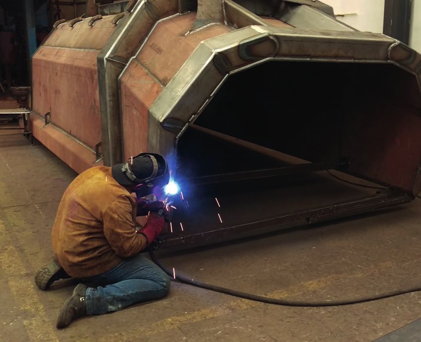
Additional variants in EN 14610 are flux cored     2.2 Current type
wire welding with an active gas constituent        MIG/MAG welding is carried out using direct

                                                                                                           MIG/MAG
(process no. 136) and flux cored wire welding      current, sometimes in a pulsed form, with
with inert gas (process no. 137).                  some more recent exceptions. Here, the
In MIG/MAG welding (Figure 2), a wire              positive pole of the power source is on the
electrode (5) is fed from the spool by a wire      electrode (wire tip) and the negative pole on
feed motor and electrically contacted and          the workpiece. A few flux cored wires (e.g. self-
                                                   shielded flux cored wires) are welded with
                                                   reverse polarity. More recently, alternating
                                                   current with special characteristics is also
                                                   used for very special applications, e.g. for
            3                              5       MIG welding on very thin aluminium sheets.

        4
                                                   3. Filler metals and
                                                      auxiliary materials
                                                   3.1 Wire electrode types
                                                   Wire electrodes for MIG/MAG welding of
                                               1   unalloyed steels and fine-grained steels
  2                                                are standardised in EN 14341. The standard
                                                   classifies eleven types of welding wires
Figure 2: Metal gas shielded arc welding           according to their chemical analysis. It also
(MIG/MAG) principle                                contains types of welding wire that are only
                                                   common in other European countries. Of the
                                                   compilation given in Table 1 for unalloyed
fed through the contact tip (4) immediately        steels, G2Si1, G3Si1 and G4Si1 grades are
before it exits the welding torch. The arc (2)     primarily used in Germany. They contain
can thus burn between the wire electrode           increasing quantities of silicon (Si) and
end and the workpiece (1). The shielding           manganese (Mn) in the order given. The
gas flows from the shielding gas nozzle (3),       respective average percentages are 0.65 to
which concentrically encloses the wire             0.9% silicon and 1.10 to 1.75% manganese.
electrode. The arc and the weld metal are          For fine-grained steels, grades G4Mo, G3Ni1
thus protected from the atmospheric gases          and G3Ni2 are also used (Figure 3).
oxygen, hydrogen and nitrogen. In addition
                                                   EN 17632 contains flux cored wire electrodes
to its protective function, the shielding
                                                   for welding these steels. Depending on
gas has other purposes. It determines the
                                                   the composition of the filler, rutile types,
composition of the arc atmosphere, affects
                                                   basic types and metal powder types are
its electrical conductivity and therefore the
                                                   differentiated (Figure 4). In addition to
welding characteristics. In addition, the
                                                   flux cored wires for MIG/MAG welding,
shielding gas affects the chemical analysis of
                                                   EN 17632 also standardises self-shielded flux
the resulting weld metal through the pick-up
                                                   cored wires, which are welded without any
and burn-off processes. Therefore, it also has
                                                   additional shielding gas. Wire electrodes for
a metallurgical effect.
                                                   welding creep-resistant steels

                                                                                                       5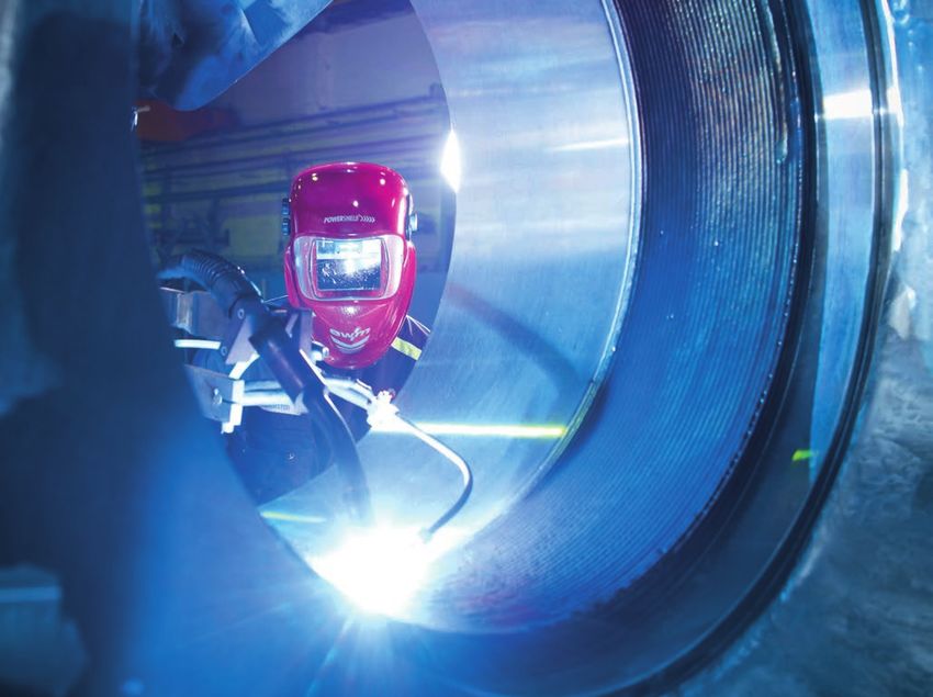
MIG/MAG Welding Dictionary

    Table 1: Example wire electrode

    EN 14341                         Wire electrode             G 46 2 M             G4 Si 1
                                           Table 1a                                                       Table 1d
                                           Table 1b                                                       Table 1c

    Table 1a                                                                  Table 1b
     ID for strength and                                                                 Code for
     elongation properties of the weld metal                                          impact energy
          ID        Minimum yield Tensile strength            Minimum           Code Temperature for minimum
                       strength1           (N/mm2)          elongation at              impact energy 47 J (°C)
                       (N/mm2)                                break 2 %          Z        No requirement
          35              355              440–570                22             A              +20
          38              380              470–600                20              0              0
          42              420              500–640                20              2             -20
          46              460              530–680                20              3             -30
          50              500              580–720                18              4             -40
     1
       The lower yield strength (ReL) applies. If the yield strength is          5             -50
        not clear, 0.2% (Rp0.2) should be used.                                   6             -60
     2
        Measuring length is equal to five times the sample diameter.

    Table 1c
                                                    Code for shielding gas
           Code                                                     Meaning
            M             If the classification has been carried out with the shielding gas EN 439-M2, mixed gas
                                                                without helium.
            C            If the classification has been carried out with the shielding gas EN 439-C1, carbon dioxide.

    Table 1d
                                    Code for the chemical analysis of wire electrodes
         Code                                  Chemical analysis in % (m/min) 1, 2, 3
                     C             Si        Mn       P         S        Ni          Mo            Al      Ti and Zr
       G0                                       Any additional agreed composition
     G2Si1        0.06–0.14     0.5–0.8 0.9–1.3 0.025 0.025             0.15        0.15          0.02      0.15
     G3Si1        0.06–0.14     0.7–1.0 1.3–1.6 0.025 0.025            0.15         0.15          0.02      0.15
     G4Si1        0.06–0.14     0.8–1.2 1.6–1.9 0.025 0.025            0.15         0.15          0.02      0.15
     G3Si2        0.06–0.14     1.0–1.3 1.3–1.6 0.025 0.025            0.15         0.15          0.02      0.15
      G2Ti        0.04–0.14     0.4–0.8 0.9–1.4 0.025 0.025            0.15         0.15        0.05–0.2 0.05–0.25
     G3Ni1        0.06–0.14     0.5–0.9 1.0–1.6      0.02     0.02    0.8–1.5       0.15          0.02      0.15
     G2Ni2        0.06–0.14     0.4–0.8 0.8–1.4      0.02     0.02    2.1–2.7       0.15          0.02      0.15
     G2Mo         0.08–0.12     0.3–0.7 0.9–1.3      0.02     0.02     0.15      0.4–0.6          0.02      0.15
     G4Mo         0.06–0.14     0.5–0.8 1.7–2.1 0.025 0.025            0.15      0.4–0.6          0.02      0.15
     GG2Al        0.08–0.14     0.3–0.5 0.9–1.3 0.025 0.025            0.15         0.15       0.35–0.75    0.15
     1
        If not specified: Cr ≤ 0.15, CU ≤ 0.35 and V ≤ 0.03. The percentage of copper in the steel plus coating
        may not exceed 0.35%.
     2
        Individual values in the table are maximum values.
     3
       The results must be rounded to the same decimal place as the specified values given in ISO 31-0,
       Appendix B, Rule A.

6   www.ewm-group.com/en/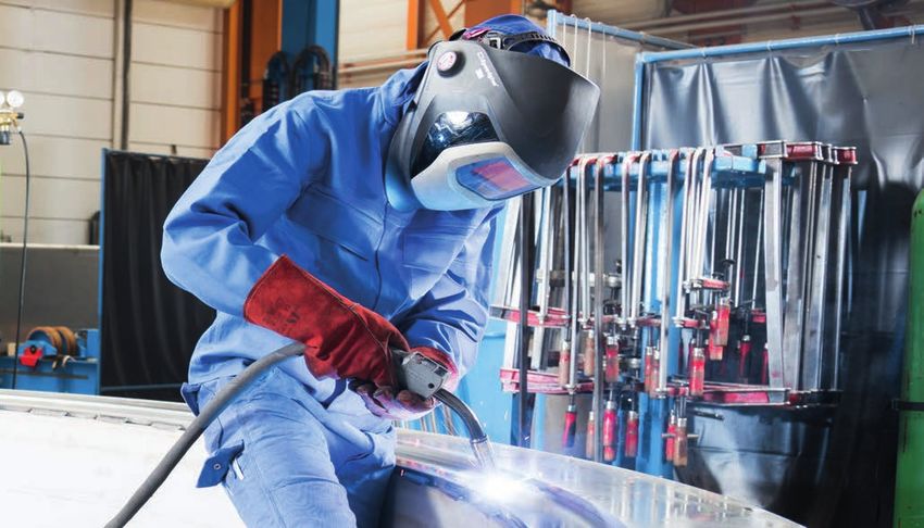
MIG/MAG
Figure 3: MAG welding in rail vehicle construction

are standardised in EN 21952; flux cored wire        3.2 T echnical delivery conditions for
electrodes for these steels are standardised              wire electrodes and flux cored wire
in EN 17634. The wire electrodes range from               electrodes
the molybdenum alloy version to wires with           Wires, rods and wire electrodes for gas
1%, 2,5%, 5% and 9% chromium and the wire            shielded arc welding are produced by
electrode with 12% chromium. Additional              cold drawing, flux cored wire electrodes
alloying elements are vanadium and tungsten.         also by cold rolling or folding in certain
Flux cored wire electrodes are available with a      manufacturing processes.
chromium constituent up to 5%.
                                                     Standardised diameters and permissible
Wire electrodes for welding stainless and            limit sizes for wire electrodes and flux cored
heat-resistant steels are standardised in            wire electrodes can be found in EN 544. The
EN 14343; flux cored wire electrodes for these       diameters range from 0.6 mm to 4.0 mm.
steels are standardised in EN 17633. The             The most common diameters of solid wires
standards classify additives for martensitic/        for MIG/MAG welding are 0.8 mm, 1.0 mm,
ferritic chromium steels, austenitic steels,         1.2 mm and 1.6 mm. The flux cored wires
ferritic/austenitic steels and fully austenitic      usually start at a diameter of 1.0 mm. However,
high corrosion-resistant steels as well as           they are also used in greater diameters such
special and heat-resistant types.                    as 2.4 mm or 3.2 mm.
A corresponding European standard is available       Unalloyed and low-alloy wire electrodes are
for wire electrodes for welding aluminium and        generally used with a copper-plated surface.
aluminium alloys: EN ISO 18273.                      The copper plating

                                                                                                       7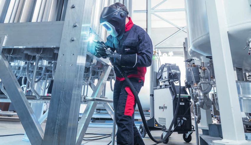
MIG/MAG Welding Dictionary

    Figure 4: Gas-shielded metal-arc welding of high-tensile steels in crane construction using flux cored wires

    serves to protect against corrosion, reduces             arc welding and cutting are standardised in
    sliding resistance during feeding and                    this standard. The shielding gases are divided
    improves the current contact. Flux cored wire            into seven groups and additional subgroups
    electrodes can only be copper-plated if they             (Table 2).
    have a closed coating without an air gap.                Group R contains argon-hydrogen mixtures
    High-alloy wires cannot be copper-plated                 which have a reducing effect. In addition to
    galvanically or in the pool. They are supplied           argon and helium, the gases in Group R1 are
    with a bare white surface. Aluminium welding             used in TIG and plasma welding, while gases
    wires with a bare surface are also used.                 in subgroup 2, which have a higher hydrogen
    Because drawing agents can be pressed into               content (H) are used in plasma cutting and
    the soft surface of the aluminium, which can             backing (purging gases).
    subsequently lead to pore formation during
                                                             The inert gases are collected in Group I,
    welding, shaving is performed on quality
                                                             including argon (Ar) and helium (He) as well as
    wires before finishing.
                                                             argon/helium mixtures. They are used in TIG,
    Wire-type welding consumables for gas                    MIG and plasma welding as well as for backing.
    shielded arc welding are supplied on plastic,
                                                             The large M group, which is further subdivided
    mandrel or wire spools. Large packing drums
                                                             into M1, M2 and M3, combines mixed gases
    such as drums are also available.
                                                             for MAG welding. Here, too, there are three or
    Further information: EWM welding                         four subgroups in each group. The gases are
    consumables manual                                       ordered from M11 to M33 according to their
                                                             oxidation behaviour. M11 is slightly oxidising,
    3.3 Shielding gases                                      M33 is the most strongly oxidising. The main
    Shielding gases for MIG/MAG welding can                  constituent of these gases is argon. Oxygen
    be found in EN 14175. All shielding gases for            (O2) or carbon dioxide (CO2), or oxygen and

8   www.ewm-group.com/en/
Table 2: Classification of shielding gases for arc welding and cutting (EN 14175)

                                                                                                                   MIG/MAG
        Short                     Components in volume percent
    designation 1
                                                                                      Common       Remarks
                          Oxidising                 Inert       Reducing     Inert   application
        ID
Group number
                       CO2          O2         Ar       He          H2        N2
             1                                                   > 0 to 15              TIG,
                                                                                      plasma
    R                                         Rest 2                                  welding,
             2                                                  > 15 to 35            plasma
                                                                                      cutting,
                                                                                      backing
             1                                100                                      MIG,
             2                                          100                             TIG,
     I                                                                                plasma         Inert
                                                                                      welding,
             3                                Rest > 0 to 95                          backing
             1                                                   > 0 to 5
                     > 0 to 5
             2                                                                                      Slightly
    M1                                                                                             oxidising
             3
                                  > 0 to 3
             4       > 0 to 5
             1      > 5 to 25
             2                                Rest 2
    M2                           > 3 to 10
             3       > 0 to 5                                                           MAG
             4      > 5 to 25     > 0 to 8
             1      > 25 to 50
    M3       2                   > 10 to 15
             3      > 5 to 50    > 8 to 15
             1         100                                                                         Strongly
    C                                                                                              oxidising
             2        Rest       > 0 to 30
             1                                                               100      Plasma         Inert
     F                                                                                cutting,
             2                                                   > 0 to 50   Rest     backing      Reducing
1
  If components are added which are not listed in the table, the mixed gas is designated as a special gas
  and by the letter S.
2
  Argon can be substituted up to 95% by helium.

carbon dioxide (three-component gases), are                 gases in Group C are the most strongly
mixed as active components.                                 oxidising because the CO2 decomposes at
In the range of gases used for MAG welding,                 the high temperature of the arc. Here, large
Group C includes pure carbon dioxide and                    quantities of oxygen are produced in addition
a carbon dioxide/oxygen mixture. However,                   to carbon monoxide.
the latter is not important in Germany. The

                                                                                                               9
MIG/MAG Welding Dictionary

     Table 3: Designation example for a wire/shielding gas combination compliant with EN 440

                          ID for strength and elongation properties of the weld metal
                       Minimum yield strength           Tensile strength         Minimum elongation at
           ID
                             N/mm2                          N/mm2                      break %
           35                    355                        440–570                          22
           38                    380                        470–600                          20
           42                    420                        500–640                          20
           46                    460                        530–680                          20
           50                    500                        560–720                          18

                                                                      ID for the impact energy
                                                                          of the weld metal
                                                                           Temperature for minimum impact
                                                                ID
                                                                                   energy 47 J (°C)
                                                                Z                 No requirements
                                                                A                       +20
                                                                0                        0
      EN 440 – G 46 3 M G3Si1                                   2                       -20
                                                                3                       -30
      Designation example for a wire/shielding gas
          combination compliant with EN 440                     4                       -40
                                                                5                       -50
                                                                6                       -60

     Finally, group F comprises nitrogen (N) and         penetration characteristics: The finger-
     a nitrogen/hydrogen mixture. Both gases             shaped penetration in the middle of the
     can be used in plasma cutting and purging.          seam, typical of argon-rich shielding gas,
     In addition to the oxidation behaviour, the         widens with active gas constituents.
     electrical and physical properties within the       According to a rule of thumb, the necessary
     arc and thus the welding properties change          shielding gas flow rate of a MIG/MAG system
     with the composition of the gas. By adding          is 10 to 12 litres/minute per millimetre of
     helium to the argon, the energy transfer            wire diameter. Welding torches with small
     in the arc process and the heat input into          gas nozzle openings require a slightly lower
     the workpiece are changed, among other              gas flow rate, torches with large nozzle
     things. This leads to a more energy-rich            openings require a slightly higher rate.
     arc and therefore to improved penetration           Because aluminium tends to oxidise during
     characteristics.                                    MIG welding, the flow rates are set somewhat
     If active components (O2, CO2) are added to         higher, and even noticeably higher for Ar/
     mixed gases, finer droplets are formed when         He mixed gases, due to the low density of
     the wire electrode melts and the weld pool          helium.
     displays improved flow properties, among            The pressure of the gas available from the
     other things. Energy transfer within the arc        bottle or ring line is initially reduced. The
     is also increased. This results in improved         set flow rate can be read off a manometer,

10   www.ewm-group.com/en/
which is adjusted together with a damper, However, these values are not components
or on a flow meter with a float. Modern of the designation system.
MIG/MAG
welding machines are sometimes fitted with A wire electrode for MAG welding the
electronic gas control valves. The influence of creep-resistant steel 13CrMo4.5 has the
the shielding gases on the welding process EN 21952-compliant designation EN 21952 – G
will be discussed in more detail later in the CrMo1Si.
description of the different types of arcs.
A wire electrode for MAG welding the
corrosion-resistant CrNi steel with the material
3.4 Weld metal properties number 1.4302 has the following designation
compliant with EN 14343: EN 14343 – G 19 9 L.
When choosing a welding consumable for
unalloyed steels and fine-grained structural The designation of a wire electrode for MIG
steels, the main aim is to also achieve the welding the material AlMg5 is EN 18273 – G
properties of the parent metal in terms of AlMg5Mn.
strength and toughness in the weld metal. Further information:
Here, EN 14341 offers assistance. Similar EWM welding consumables manual
to stick electrodes, a designation system
exists from which the minimum values of
yield strength and elongation at failure can
be taken as well as the strength and impact
4. Edge preparation
energy of the weld metal. The designation 4.1 Groove shapes
system is illustrated in Table 3. Figure 5 shows the most important groove
In the example used here, a G3Si1 wire shapes used for MAG welding steel.
electrode is welded under a mixed gas (M). Because the process shows such good
This welding consumable has a minimum penetration characteristics, seams with root
yield strength of 460 N/mm² (“46”), a tensile faces (butt welds, single-Y and double-Y butt
strength of 530 to 680 N/mm² and a minimum welds) can be welded using larger sheet
elongation of 20%. Impact energy of 47 Joule thicknesses without gouging, compared
is achieved at a temperature of -30 °C (“3”). to MMA welding. Where greater material
A similar system is also used to characterise thicknesses are used, it is advisable to gouge
flux cored wire electrodes in EN 17632. from the back to avoid errors. The root face
For creep-resistant steels, corrosion-resistant thickness depends on the relevant current.
and heat-resistant steels and aluminium Because aluminium materials dissipate
materials, the rule applies that the weld heat better, larger included angles of 70 to
metal should be alloyed as closely as possible 90 degrees are advisable.
to the parent metal to be welded or slightly
higher in order to achieve the required 4.2 Applying the fusion faces
material properties. For wire electrodes and
In the case of unalloyed and low-alloy steels,
flux cored wire electrodes of creep-resistant,
edges of the parts to be joined are usually
corrosion-resistant or heat-resistant steels,
bevelled by oxyacetylene cutting. High-alloy
information about the minimum yield
steels and the metals that are welded using
strength, tensile strength, elongation and
the MIG process (e.g. aluminium) can be
impact energy values of the weld metal can
melt-cut using the plasma jet.
be found in a table in the relevant standards.
11MIG/MAG Welding Dictionary
The oxidation that occurs during thermal Groove shapes compliant with EN 9692-1
cutting does not necessarily need to be Joint type Thickness of Sketch
removed. However, it may still be necessary workpiece (mm)
in special cases. The characteristics of one-sided 3–8
Butt weld
aluminium as a material in this regard are two-sided < 8
discussed in more detail elsewhere. one-sided
Single-V
3–10 with
Mechanical machining of the fusion faces butt weld
backing run 3–40
can also be recommended where there are
special requirements and low tolerances. one-sided
Single-Y
This applies particularly to pipe butt joints. 5–40 with
butt weld
backing run > 10
The modern possibilities of precision plasma
cutting or laser beam cutting come into play
in mechanised production.
4.3 Weld pool backing Double-V
two-sided > 10
butt weld
When working manually, the welder observes
the welding process and can achieve a
uniform root pass by setting the correct
current, the position of the welding torch in
the groove and the welding speed, even if the one-sided > 12
air gap varies. In the case of fully mechanised U-weld with backing
welding, on the other hand, all variables, run > 12
from the weld joint geometry and the air gap
used to the correct welding parameters with Single-V
one-sided 3–10
welding speed and deposition rate, must be with backing run
butt weld
3–30
selected appropriately. In order to make root
welding easier, weld pool backing is often
used in mechanised welding (Figure 6). Fillet weld
one-sided > 2
T-joint
If the root gap does not vary excessively, root
faces can serve as natural weld pool backing,
e.g. for butt or single-Y joints (internal weld Fillet weld
one-sided > 2
pool backing). Depending on the root face corner
two-sided > 3
thickness, the parameters when welding the joint
first pass must be selected such that the root
face is not completely melted. The remainder
of the root face can then be included when Fillet weld
one-sided > 2
lap joint
welding the backing run, with or without
gouging.
Fillet weld
double two-sided > 2
fillet weld
Figure 5
12 www.ewm-group.com/en/Artificial (external) weld pool backing consist Purging prevents, or at least reduces, the
of metal, for example. Copper is used for formation of oxidation and discolouration
MIG/MAG
most metals and alloys; the backing must on the back of the root. This is important
not be melted. Ceramic backing is now also when welding corrosion-resistant steels, for
available in numerous variants as weld pool example, because the oxidised areas of the
backing. The backing is used to prevent the welded joints become more susceptible to
weld metal from suddenly sagging at critical corrosion. After welding, it may be necessary
points. This way the molten metal is caught, to remove them by brushing, blasting or
and a correct root bead is formed. The weld pickling.
pool backing also forms the underside of the When welding pipes, the ends of the pipes
root pass. It is usually provided with a groove are blocked; the purging gas must flow into
for this purpose. the interior in a controlled manner. When
welding sheet metal, it flows out of the
openings in the weld pool backing.
Argon or an argon/hydrogen mixture can be
used as purging gas. In many cases, however,
Butt joint the inexpensive Group F purging gases in
EN 14175 can be used. These consist of a
hydrogen/nitrogen mixture, for example.
Even pure nitrogen can be used for purging,
Single-Y joint under certain circumstances.
5. Welding machines
MIG/MAG welding machines consist of
Single-V butt weld on Cu-bar the power source, the control and the wire
feeder with hose package and welding torch.
Figure 6: Typical groove shapes and weld pool
They can be used as compact machines or
backing for mechanised gas-shielded metal-arc decompact machines with an external wire
welding feeder for various applications.
In the compact machine (Figure 7), the
4.4 Purging power source, control and wire feeder are all
By purging we refer to the addition of shielding included in one casing. The operating radius
gas at the rear of the seam. This prevents the corresponds to the length of the torch hose
highly heated material from being directly package, generally 3 to 5 metres. Accordingly,
exposed to the atmosphere (oxidation). This compact machines are generally used at
is generally indispensable for TIG and MIG/ permanent workplaces, e.g. in welding
MAG welding, so that the root does not need booths or on production lines.
to be gouged again. Purging is frequently On decompact machines (Figure 8), the wire
unnecessary when MAG welding root passes. feed mechanism is located in a separate
This depends on the material used. casing and is connected via an intermediate
hose package to the power source and the
13MIG/MAG Welding Dictionary
control. The wire feeder can be transported
to the workpiece. This allows the operating
radius to be extended by up to 40 metres
compared to the compact machine.
Universal machines are therefore generally
deployed at moveable workplaces and on
construction sites. Figure 9 shows the MIG/
MAG multiprocess inverter pulse welding
machine Titan XQ puls with Expert 2.0 control
in the power source and HP-XQ control in the Figure 7: Compact, step switch controlled MIG/
MAG welding machine with integral wire drive
wire feeder.
5.1 Power sources
The task of the power source is to supply the
welding process with the necessary electrical
energy. This includes reducing the high grid
voltage to values that are safe and useful for
welding; at the same time, the high current
required is made available. Because only
direct current is used for MIG/MAG welding,
with a few exceptions, only rectifier machines
or inverters are used as power sources.
The welding rectifier consists of the mains
transformer and a downstream rectifier set Figure 8: Decompact, step switch controlled MIG/
(diodes). While the transformer converts the MAG welding machine with separate wire drive and
high voltage and low current of the mains water cooling
grid into electrical power with low voltage
(10 to 50 V) and high current (50 to 500 A),
the rectifier set converts the alternating
current or three-phase current supplied by
the transformer into direct current.
Different currents and voltages are required
for different welding tasks. The power sources
must therefore be adjustable. On simple
MIG/MAG welding machines, tappings of the
turns on the transformer are switched using
a step switch.
Figure 10 shows a schematic diagram of a
step switch controlled machine.
Figure 9: Titan XQ MIG/MAG multiprocess inverter
welding machine
14 www.ewm-group.com/en/By incorporating more or fewer turns of the More modern MIG/MAG machines are
primary coil, the transformation ratio of the equipped with inverters as power sources.
MIG/MAG
transformer changes and with it the voltage The inverter is an electronically controlled and
on the secondary side. regulated, primary-switched power source.
In the case of slightly more complex power After using analogue and secondary-switched
sources, the current in the rectifier section is electronic power sources for decades,
adjusted using a controllable rectifier (known development now concentrates on these
as thyristors). Figure 11 shows a schematic primary-switched machines. They utilise a
diagram of such a machine. completely different working principle than
conventional power sources (Figure 12).
By controlling the thyristors accordingly,
more or less large proportions of the AC The power supplied by the electrical mains
half-waves are used. As a result, the welding grid (voltage, current, 50 Hz) is first rectified
voltage changes. This relatively simple using a set of diodes and then
technology is now obsolete.
3
4
2
5
1
DC output
1 Mains connection
2 Step switch
3 Transformer
4 Rectifier
5 DC output
Figure 10: Welding power source schematic with step switch control
2
3
5
1
1 Mains connection
4 2 Transformer
3 Thyristor set
4 Control electronics
5 DC output
Figure 11: Schematic of an infinitely adjustable welding power source with thyristor
control
15MIG/MAG Welding Dictionary
2 3 4 5 6
1 7
50 kHz
1 Mains connection (50/60 Hz) 5 Secondary rectifier (diodes)
2 Primary rectifier (diodes) 6 Medium frequency choke
3 AC unit (transistors) 7 DC output
4 Medium frequency transformer
Figure 12: Block diagram of a modern inverter power source
divided into short blocks by fast switching.
This switching is performed by fast-working
U [V]
electronic switches, the IGBT transistors. 1
The first transistorised inverters work with
switching frequencies of around 20 kHz.
In the meantime, with more developed 2
3
transistor switches, frequencies of up to
100 kHz are possible. 4
After quickly switching the power on the I [A]
primary side, it is transformed to the power 1 Constant voltage characteristics
required on the secondary side at a high 2 Flatly falling characteristics
current and low voltage. An approximately 3 Steeply falling characteristics
rectangular AC voltage is created 4 Constant current characteristics
downstream of the transformer, which is Figure 13: I–V characteristics
subsequently rectified again (diodes). The
high switching frequency keeps the required
mass of the transformer, which operates switched sources, the ratio between the on/
at high frequency, very small; it is strongly off times with the lowest losses is changed.
dependent on the switching frequency. This The ratio of the on/off times is cyclically
makes it possible to manufacture lightweight altered by the control in order to generate
power sources with high efficiency. pulsed current profiles. In a similar manner,
In modern welding machines, numerous the current can be ramped up or down as
functions that are achieved in conventional required when the welding process is started
power sources using conventional electrical and stopped.
components such as resistors, chokes, Inverter technology made possible the
capacitors and switches are now electronically precisely regulated power source, which had
solved by the control. The control of these long been in demand for welding technology.
power sources is therefore at least as As a control device, an electronic controller
important as the power unit. To adjust the continuously measures welding current and
output power, for example when using with voltage and compares these values
16 www.ewm-group.com/en/with the specified nominal values. If the The wire feed mechanism must handle
current actual values change, e.g. due to the surface of the wire electrode with care.
MIG/MAG
undesirable changes in the welding process, The wire feed rolls must therefore have
the control corrects this within a few a sufficiently large diameter to prevent
microseconds (typically 0.1 ms). In a similar excessive surface pressure on the wire
way, the short-circuit current in the welding surface.
process can be limited to reasonable values. Compared to a 2-roll drive, the wire can be
The technology described here results in conveyed with less contact pressure and still
significantly better efficiencies with minimal slip-free in 4-roll drives. In the case of 4-roll
open-circuit losses and very good inverter drives, all the rollers are frequently interlocked
device cos φ (phi). and driven together by a (powerful) motor.
In the simplest case, the electrical behaviour Figure 14 allows a look into a wire feeder with
of the welding machines (power sources) 4-roll drive. This results in a 3-point support of
discussed here is characterised by the shape the wire circumference between the rollers,
or position of the machine’s I–V characteristic. which is gentle on the surface while offering
This can be a constant voltage characteristic optimal traction. Knurled rollers are often
or what is known as a constant current used for flux cored wire and U-groove rollers
characteristic. In between these, any other are used for soft wires (Figure 15).
form of I–V characteristic, from flatly falling
Careful handling of the wire surface is
to steeply falling is possible (see diagram in
important because abraded wire particles
Figure 13). This description, also referred to
(metal particles) are conveyed into the hose
as the “static characteristic of the source”, has
package and may thus clog it after a short
an important influence on the operation and
stability of each and any arc process.
5.2 Wire feeders
In the wire feeder, the wire electrode moves at
a selectable speed towards the arc process by
means of wire feed rolls. It is drawn from the
spool and pushed through the hose package.
The welding torch is located at the end.
The rotating speed of the wire feed rolls is
driven by an infinitely adjustable DC gear
motor.
In modern machines that allow a controlled
welding process, the motor speed, and thus
the wire feed speed, is measured by a speed
sensor and precisely controlled regardless of Figure 14: Modern wire feeder with
4-roll drive
the load.
In MIG/MAG welding, wire feed speeds
between 1 and 20 m/min are common –
depending on the wire diameter – with high-
performance variants moving up to 30 m/min.
17MIG/MAG Welding Dictionary
time. Increased metal abrasion also occurs (e.g. Teflon) is employed. Plastic guides have
when the wire feed rolls are worn or damaged. a more favourable coefficient of friction than
Their condition must therefore be regularly steel. Control signals can be sent from the
checked. New wire feed rolls must be free of welding torch to the controls through the
burrs on and in the grooves. control cable assembly. The torch trigger is
The pressure of the wire feed rollers is located on the torch grip and can be used to
adjustable and must be selected depending control the necessary welding functions.
on the wire type according to the machine Figures 16 to 18 show some common
manufacturer’s information (scale on the welding torch types. Curved welding torches
pressure sleeves). (Figure 16) are most commonly employed.
They are lightweight, and the arc generally
5.3 Hose package and welding torch reaches the weld location easily. The welding
torch in Figure 17 offers a special technology
The hose package that connects the MIG/
with the remote control integrated in the
MAG welding torch to the welding machine
handle.
or wire feeder contains all the necessary
supply lines: the welding current lead, the An additional welding torch type is the
shielding gas supply, the wire feed hose and push/pull torch (Figure 18). With the push/
the control cable assembly. On machines pull drive, a wire feed motor mounted in
designed for higher currents, the cooling the torch handle pulls the wire electrode,
water supply and return are also included. while the drive, which is located in the
machine, pushes the wire into the hose
In water-cooled welding torches, the current
package. This allows even soft and thin wires
lead is within the water return. The line
to be fed safely. A push/pull drive is also
cross-section is therefore smaller and the
frequently employed in robot systems and
hose package lighter and more flexible than
in mechanised welding machines in order to
for welding torches without water cooling.
be able to safely transport the wire electrode
When welding unalloyed and low-alloy
over long distances. Both drives must be
steel, the wire guide hose consists of a steel
synchronised using electronic means.
liner. If wire electrodes made of chrome-
nickel steel as well as aluminium and other
metals are used, a wear-resistant plastic hose
e.g. UNI rolls for Ø 1 mm e.g. Ø 1 mm with U-groove e.g. Ø 1 mm with V-groove,
to 1.2 mm with V-groove (blue/red): (blue/yellow): for aluminium knurled (blue/orange):
for stainless steel, steel for flux cored wire
Figure 15: Drive rolls with differing groove geometries
18 www.ewm-group.com/en/These days, small-scale, powerful wire drive
systems installed on the robot wrist are used
MIG/MAG
in robot systems; they feed the wire electrode
directly from a wire drum via a low-friction
conveying path and without additional drive
technology.
Figure 19 shows a cross-section through
a modern welding torch.
Because of the high peak currents (400 A to
600 A), current transfer from the contact tip
to the wire electrode is not uncritical. Reliable
contacting, and thereby an interference-
Figure 16: Standard MIG/MAG welding torch for free and reproducible welding process, is
manual welding only possible if the wire has a bare, metallic
surface and – due to its curvature (“shape”)
or by measures on the torch side – is pressed
against the contact tip inner bore (“forced
contact”). In the event of interferences at this
point, the wire movement is usually blocked
briefly and irregularly, thus significantly
affecting the welding process.
5.4 Control
A number of functions can be set on the
welding machine’s control. For example, you
can move between non-latched and latched
operation. In addition, a wire electrode creep
Figure 17: MIG/MAG welding torch with integral speed when igniting and a burn-back time
display of the arc when the welding is ended can be
defined. The adjustable, low speed of the wire
electrode during ignition makes the ignition
process safer because the arc, which at the
beginning still burns weakly on the cold
material, is not immediately smothered by
the wire pressing from behind. The defined
burn-back time prevents the electrode from
sticking in the end-crater. To achieve this,
wire feeding is switched off slightly earlier
than the welding current. However, if the
burn-back time is excessively long, the wire
can burn back to the contact tip and stick
there. An additional program can prevent
Figure 18: MIG/MAG welding torch with push/pull an excessively large droplet, which would
drive and exchangeable torch neck interfere with re-ignition, from remaining
19MIG/MAG Welding Dictionary
Greater contact tip and screw base cross-sections ensure
optimal heat dissipation under high loads.
Figure 19: Cross-section through MIG/MAG welding torch head
at the end of the wire after welding has The latest generation of inverter welding
ceased. Here, the droplet formed on the machines can work on mains voltages in an
wire immediately before welding is ended extended range around the nominal voltage
is detached by a current pulse. Modern MIG/ of up to -25%/+20% and thus facilitate
MAG systems also allow the current to be operation at different deployment locations.
ramped up at the beginning and reduced Changes in the mains voltage within this
correspondingly at the end of the weld. range have no effect on the welding process.
A further function, called soft start Thanks to modern electronics, the machines
technology, ignites with a low current and are highly efficient during welding and
reversing wire movement, making a low- consume little energy in idle phases. To
spatter and reliable process start possible. achieve this, these machines switch off the
Using what is known as process switching cooling circuit pump and the machine fan
between types of arcs with increased when they are at a standstill for a long time,
or reduced heat input, welds can be so that energy consumption in standby
implemented and designed in a variety of assumes very low values.
different ways.
The welding circuit in the leads between the
machine and the arc location has specific
values for ohmic resistance and inductance.
They depend on the cable length, cross- Wire electrode
section and geometry of the installation and
may change the current and/or voltage curve
shapes and thus the welding results. Modern
machines are capable of determining the
resistance and inductance values and of
compensating for their influence. This
ensures reproducible welding results.
Figure 20: Schematic of pinch effect [1]
20 www.ewm-group.com/en/Voltage U [V]
MIG/MAG
ILB = Pulsed arc
KLB = Short arc
ÜLB = Transitional arc
SLB = Spray arc
Current I [A]
Figure 21: Location of the working areas
The electronic log-on function can prevent magnetic field and is a force directed radially
unauthorised personnel from starting the inwards (Figure 20). It constricts the molten
machine or changing the defined parameters. end of the electrode and “pinches” individual
In critical applications, welding data should drops from it.
be continuously recorded and certain DIN 1910-4 differentiates and describes the
parameters monitored. This data can be arc types listed in Table 4.
stored together centrally in a network of The typical material transition forms at
numerous active welding machines. The uniform current occur in part in the lower
microcomputer systems in modern welding power range, i. e. at low currents and voltages,
machines are capable of this (see ewm Xnet). and in part in the medium or upper power
Further information: range.
www.ewm-group.com/sl/brochures Figure 21 schematically shows their position
in the I–V diagram.
6. Material transfer during The pulsed arc is available across a very broad
MIG/MAG welding power range.
6.1 Arc ranges
Depending on the specified welding 6.2 Short arc
parameters and the shielding gas used, The short arc occurs in the lower power
different material transition forms, the arc range at low currents and arc voltages. Not
operating states, occur in MIG/MAG welding. only does its name indicate that this is a
Here, both physical phenomena such as geometrically short arc, it is also referred to
surface tension and viscosity of the molten as a short(-circuit) arc because of the nature
metal, gravity and plasma flow as well as of the droplet transfer. Figure 22 shows the
electrical forces such as the Lorentz force are different droplet transfer stations.
involved. The latter electromagnetic force, Under the influence of the heat from the arc,
in particular, has a dominant influence on a small droplet (a) forms at the end of the
droplet transitions that occur in free fall. The electrode, which, thanks to the short arc and
Lorentz force, here also referred to as the
pinch effect, results from the surrounding
21MIG/MAG Welding Dictionary
Table 4
Arc types compliant with DIN 1910-4
Name Material transfer
Spray arc ultrafine to fine droplets > practically short circuit-proof
Long arc coarse droplets > not short circuit-proof
Short arc fine droplets > in short circuit
Pulsed arc Adjustable droplet size and frequency >
practically short circuit-proof
caused by the wire movement, soon comes 6.3 Long arc (100% CO2)
into contact with the weld pool. A short circuit
occurs: The arc extinguishes (b). The droplet The long arc occurs in the medium and
is absorbed by the weld pool as a result of the upper power range when welding with pure
surface tensions. The arc subsequently ignites CO2 or mixed gases with high CO2 content.
again at regular intervals (c). This process is Large-volume droplets and increased
repeated at irregular intervals, depending on spatter ejection are characteristic. The deep
the shielding gas used, approximately 20 to penetration reduces the risk of lack of fusion
100 times a second. During the short circuit in certain applications.
phase, the current increases with a delay.
The long arc is rarely used in Europe.
Because of the small size of the droplet, the
short-circuit phase is short and there are no
excessive current spikes. Using conventional 6.4 Spray arc
power sources, the rate of current increase is With argon and argon-rich mixed gases, the
limited to reasonable values by an adapted arc envelops the lower electrode end at the
choke in the welding circuit. This way, contact with the droplet, allowing the pinch
following the short circuit, the arc is re-ignited effect to optimally develop if the current is
softly and without significant spatter sufficient. The end of the wire is constricted;
formation. In inverter welding machines, individual drops are detached from the
the electronic open-/closed-loop control electrode (Figure 23).
(software) flexibly prevents the current from
increasing excessively in the droplet short
circuit.
The short arc is a relatively “cold” process
with low electrical power conversion, low
penetration and viscous molten metal. It
occurs under all welding shielding gases
and is particularly suitable for welding root
passes, thin sheets and in positional welding.
(a) (b) (c)
Figure 22: Droplet transfer in short arc
22 www.ewm-group.com/en/input and penetration depth are in the mid-
range between the processes discussed
MIG/MAG
above (Figure 24). This arc is avoided where
possible.
6.6 Pulsed arc
A characteristic of the pulsed arc is a rapid,
regular change between phases with high
and phases with low power, which is forced
by the power source.
Depending on the “modulation” (closed-
loop control instead of “control principle”)
Figure 23: Droplet transfer in spray arc of the power source, the parameters for
this arc operating mode are the wire feed
Here, material transfer is short circuit-proof speed, the basic current or the basic voltage,
and low-spatter. the pulse current or the pulse voltage, the
pulse duration and the pulse frequency. As
The spray arc occurs with argon-rich shielding
Figure 26 shows, one droplet detaches from
gases in the upper power range. With this
the electrode tip in the pulse phase under
type of arc, a large, hot weld pool forms,
the influence of the pinch effect, provided
normally making the process unsuitable for
the parameters are selected correctly. This
positional welding (PC–PF, Figure 25).
results in a regular welding process with fine
droplets and low-spatter.
6.5 Transitional arc
The pulsed arc can be used over almost
The transitional arc occurs between the short the entire power range and is also suitable
arc on the one hand and the spray or long arc for positional welding at low and medium
on the other. A mixed material transfer, partly currents.
in short circuit, partly in free fall, is typical for
this. Spatter increasingly forms in this range,
even with argon-rich mixed gases. The heat
1
2
3
1: Wire electrode
2: Molten metal
a) b) c) 3: Arc
Figure 24: Droplet transfer in transitional arc
23MIG/MAG Welding Dictionary
6.7 Special forms of material transfer At currents that are higher than those of the
In addition to the standard arc types described conventional spray arc – that is, at wire feed
above, special forms, that have only come to rates of more than 18 m/min for 1.2-mm wire,
the fore in recent years, also exist. for example – the high-performance spray
arc occurs under mixed gases. However, this
is accompanied by such a deep penetration,
even cutting under certain circumstances,
PA that it can lead to faults in the seam.
If the stick-out and the voltage are increased,
PB the arc begins to rotate in this power range
and the penetration widens. The rotating
arc is used when the aim is to increase the
deposition rate. The rotating arc is also used
if the welding speed for filler and cover
passes on butt welds and fillet welds needs
PC
to be increased on thick-walled components.
The risk of pore formation as a result of gas
PF/PG
turbulence is high; the process should be
used with great caution.
PD
PE
Figure 25: Welding positions in accordance with
EN ISO 6947
Current I [A]
Time t [ms]
Figure 26: Droplet transfer in pulsed arc
24 www.ewm-group.com/en/U [V]
MIG/MAG
1
4
3
2 1 Long arc
2 Short arc
3 Power source
characteristic
4 Operating point (OP)
I [A]
Figure 27: Arc ranges for MIG/MAG welding
The high-performance short arc is a process the welding machine’s coarse and fine step
with a material transfer in the typical short- switches. Together with a suitably defined
circuit transition area. It occurs at currents wire feed speed, a favourable arc length is
in the conventional spray arc range, but at a achieved. Figure 27 shows how the position
significantly lower arc voltage. of the operating point changes when the
With some exceptions, the high-performance settings of the power source and the wire
MIG/MAG welding variants discussed here feed speed are changed.
are only used in fully mechanised welding. The operating point (OP) is the intersection
between the defined power source
7. Setting the welding characteristic and the arc characteristic. It
parameters is characterised by the current Is(OP) and
the voltage Us(OP). If the wire feed speed
7.1 Setting on conventional is increased, the arc is shortened, and the
welding machines operating point moves to the right on the
In contrast to MMA welding and TIG welding, source characteristic – the current increases.
two adjustment processes are necessary for If the wire feed speed is reduced, the OP
MIG/MAG machines. This is explained using moves to the left instead. The required
the example of the relatively simple settings current can thus be specified via the wire feed
on a step switch controlled machine (welding potentiometer. However, the arc is shortened
rectifier). as a result of the higher wire feed speed. To
Constant voltage sources or – in most cases – prevent it from becoming too short, the
those with a flatly falling I–V characteristic are voltage must be simultaneously increased.
used for MIG/MAG welding. The approximate
voltage required is therefore selected by
setting a specific characteristic (step) on
25MIG/MAG Welding Dictionary
For a higher voltage, a higher characteristic Figure 28 shows the working areas for an
must be set on the step switch; if a lower arc Si/Mn alloy steel wire electrode and two
voltage is desired, a lower characteristic must different mixed gases.
be set. The source characteristics usually fall. All operating points within the sketched
This means that if one required parameter is working area lead to favourable welding
adjusted, the other also changes slightly. This conditions. Operating points below this
mutual influencing is only absent in constant range mean excessively short arcs, operating
voltage sources (horizontal power source points above lead to excessively long arcs.
characteristic). The working areas always apply only to a
For optimal welding conditions, the arc may specified combination of wire electrode and
be neither too short nor too long. Droplet shielding gas type.
short circuits and therefore spatter often When welding with pulsed arc technology,
occur if the arc is too short. The short circuits the material transfer is largely free of short
can be recognised by a typical backfiring circuits. At low and medium currents, the
noise emanating from the arc. As the length range limits shift here to somewhat higher
of the arc increases, the risk of ambient arc voltages.
air entering the arc area also increases.
This in turn increases the risk of pores and
undercuts, among other things. The welder 7.2 Synergetic settings
for welding processes
can recognise the excessively long arc
optically and from the hissing noise of the The operation of modern welding machines
arc. The range of favourable operating points is becoming increasingly difficult due to the
runs approximately diagonally through the variety of functions and parameters. However,
I–V diagram. This is the working area where the welding parameters can be very easily set
welding should be performed. on modern MIG/MAG machines.
Voltage Us [V]
%
/CO 2 18
Ar 82%
9 2 % / CO 2 8%
Ar
1
1 Spray arc
2 2 Transitional arc
3 Short arc
3
Current Is [A]
Figure 28: Working areas for two argon mixed gases
26 www.ewm-group.com/en/This development began decades ago with
the so-called “one-knob operation”, in which
MIG/MAG
the power, by means of an infinitely adjustable
source (voltage) characteristic, and the wire
feed speed could be adjusted appropriately
at the same time by simply turning a rotary
knob. A certain amount of correction to the
operating point was possible via an optional
second knob.
In the meantime, it has become the
standard for many MIG/MAG machines,
such as the EWM multiprocess machines Figure 29: Picomig control
Titan XQ, Phoenix puls, Taurus Synergic S or
Picomig Synergic/puls (Figure 29), that the achieve this, certain conditions must apply:
intrinsically complicated setting of modern The wire feed speed is usually held constant
machines is much simpler. The ideal “working during MIG/MAG welding (see section on
characteristics” for the most frequent wire feeders). If the welding machine supplies
welding tasks are stored in the machine. The the arc process with a stable voltage – that is,
machine operator only defines the so-called constant voltage behaviour or a flatly falling
JOB using the touch buttons or by selection I–V characteristic (see Figure 27) – a “simple”
in the corresponding menus. This includes arc process itself (e.g. in spray arc operating
the material to be welded, the required wire mode) can balance the stick-out and keep
diameter, the material of the wire or the the arc length stable. External interferences,
welding consumable and the shielding gas e.g. caused by changes in distance, may not
used. This calls up the pre-programmed, be completely eliminated, but the welding
ideal working characteristic for the welding process remains fundamentally stable.
task (“synergic characteristic”). The power This is illustrated in the following diagram
can now be infinitely adjusted using a (Figure 32): The arc process characteristic
potentiometer/voltage correction (in volts). shifts to the right in the I–V diagram as a
A correction button is available for individual result of a change in the distance between
requirements for the most favourable arc the welding torch and the workpiece (a -> b);
length. Figures 30 and 31 show controls a new operating point OP2 is created with an
of modern welding machines. They allow increased welding current. The higher current
numerous additional settings. leads to a greater wire deposition rate. In
turn, this causes the arc to become longer.
7.3 Stabilisation/control of MIG/MAG It forms a new equilibrium with the shorter
processes stick-out. If the original distance between the
MIG/MAG arc processes are not intrinsically welding torch and the workpiece is reached
stable: The feed speed of the wire electrode again (b -> c), an equilibrium between the
and the voltage must always be the same. wire and arc length is achieved as in (a). The
Only in this way can a balance between stick- operating point is once again at OP1.
out and the arc length be maintained. To
27MIG/MAG Welding Dictionary
an adapted choke (inductance). This prevents
the current in the welding circuit from
increasing excessively; the welding process is
not disturbed (see Figure 32). If the distance
shortens, the process may react with more
frequent droplet transfers, and if the distance
increases, with fewer. The process therefore
remains stable as long as the changes in
distance do not occur suddenly.
Stabilisation is more complicated when
arc welding using pulse technology (see
Figure 26), because the basic phases must
Figure 30: Control of a synergy-programmed
MIG/MAG machine (high-tech)
be operated at low power with controlled
current across a steep characteristic. This
dispenses with stabilisation in these phases.
In many cases, the (short) pulse phases are
operated with a controlled voltage using a
flat characteristic. This allows the process-
internal stabilisation to work.
This simple stabilisation method fails at
low pulse frequencies with long basic
phases without stabilisation just as with
non-ferrous wire materials. Instead, the
entire pulse process is operated under a
controlled current: It runs across steep source
characteristics in all phases. However, the
Figure 31: Control of a synergy-programmed balance between stick-out and arc length
MIG/MAG machine (standard) must then be established using a complex,
electronically assisted control system. This
The compensation processes described take
technology continuously measures current
place in the tenths of a second range. The
and voltage and uses information from the
process is referred to in welding technology
welding process. In doing so, it utilises an
(not entirely correctly) as “internal regulation”
arc model. The average welding current is
or (better) as “internal self-balancing”.
adjusted in a suitable form depending on the
On the other hand, if the welding machine results of the measurement. This counteracts
has a steeply falling or constant current unintended changes in the process.
characteristic as used in other welding
The parameters of this arc model depend on
procedures (e.g. TIG), a stable MIG/MAG
materials, shielding gases, operating modes,
process is not possible. There can be no, or
working areas and many other influencing
only an insufficient, change in the current I.
factors. The welding machine manufacturers
Short interruptions in the arc caused by determine these parameters with great
droplet transfers in the short circuit (between effort in their laboratories and incorporate
the wire tip and the weld pool), as they them in the microcomputer-based electronic
occur in the “short arc” and “transitional arc” systems (also see Section 7.2 – Synergic
processes, for example, are compensated by programming).
28 www.ewm-group.com/en/You can also read