Wetting Properties of Aluminium Surface Structures Fabricated Using Direct Laser Interference Patterning with Picosecond and Femtosecond Pulses
←
→
Page content transcription
If your browser does not render page correctly, please read the page content below
JLMN-Journal of Laser Micro/Nanoengineering Vol. 16, No. 1, 2021
   Technical Communication
       Wetting Properties of Aluminium Surface Structures Fabricated
       Using Direct Laser Interference Patterning with Picosecond and
                             Femtosecond Pulses
  Stephan Milles*1, Johannes Dahms1, Bogdan Voisiat1,2, Simonas Indrišiūnas2, Gediminas Račiukaitis2 and Andrés Fabián
                                                        Lasagni1,3
              1
                Institute for Manufacturing Technology, Technische Universität Dresden, George-Baehr-Str. 3c,
                                                   01069 Dresden, Germany
                 2
                   Center for Physical Sciences and Technology, Savanoriu Ave. 231, 02300 Vilnius, Lithuania
             3
               Fraunhofer-Institut für Werkstoff- und Strahltechnik IWS, Winterbergstr. 28, 01277 Dresden, Ger-
                                                              many
                           *
                             Corresponding author’s e-mail: Stephan.milles@tu-dresden.de

                In this work, we report about the fabrication of textured aluminium surfaces using Direct Laser
            Interference Patterning with picosecond (70 ps) and femtosecond (400 fs) laser pulses as well as their
            wetting properties. The structuring process was performed by varying the pulse numbers from 25 to
            250, resulting in various depths ranging from 0.9 µm to 6.8 µm. The wetting analysis shows that the
            ps-patterned surfaces exhibit long-term superhydrophobic characteristics (at 21 °C and 16 % air hu-
            midity). Differently, for the fs-processed substrates, a hydrophobic character was firstly observed,
            which later (after 16 days) dropped to contact angles similar as the untreated material.
            DOI: 10.2961/jlmn.2021.01.3001
            Keywords: direct laser interference patterning, picosecond, femtosecond, aluminium 2024, wettabil-
            ity, superhydrophobicity

1. Introduction                                                       compromise between sufficiently high ablation rate and sim-
    Superhydrophobic surfaces are economically highly in-             ultaneously reduced melting effects compared to nanosec-
teresting since they are related to additional functionalities        ond pulsed ablation processes, where melting is the domi-
like corrosion-resistance, anti-icing, or the ability of self-        nant ablation phenomenon. Significantly more precise struc-
cleaning [1]. There are a wide variety of chemical and phys-          tures can be fabricated using femtosecond (fs) pulsed laser
ical technologies existing to fabricate these water repellent         sources due to the reduction of thermal losses on the material
surfaces. They are ranging from CVD and PVD treatments,               surface [19].
over chemical etching to expensive lithographical or wear-            On the other hand, this "cold ablation" also leads to reduced
intensive micro-milling processes [2–5].                              oxide formation on the surface and thus to fewer attachment
    Alternative approaches to the disadvantageous existing            points for organic components. These are adsorbed onto the
manufacturing processes are laser texturing methods, as Di-           surface by the surrounding atmosphere after ps irradiation,
rect Laser Interference Patterning (DLIP). By using this one-         for example and are responsible for a superhydrophobic
step fabrication method, a single laser beam is divided into          characteristic [20]. This functionality is also very interesting
at least two coherent sub-beams, which are then superim-              as it can prevent biofouling, contribute to drag reduction, or
posed and focused on the surface, resulting in a periodic la-         be used in the field of oil and water separation [21]. How-
ser light intensity distribution [6–10].                              ever, it is still not clear, which pulse duration (ps or fs) pro-
    DLIP has been proven as a suitable tool to fabricate mi-          vides better structuring results regarding a functional super-
crostructures on aluminium surfaces providing superhydro-             hydrophobic surface when DLIP technology is applied. The
phobic, ice-repellent, and self-cleaning functionalities [11–         dominant ablation phenomena can be described as ultra-fine
15]. The wetting characteristic of a surface besides the              ablation for both cases [22]. However, especially on materi-
chemistry is mainly controlled by the topographical condi-            als with a very low melting temperature like aluminium
tion. Typically, the surface topography is defined by rough-          (660°C), the differences between picosecond and femtosec-
ness parameters, such the root mean square height (Sq) or the         ond ablation are tremendous.
maximum height (Sz) [16]. It has been known for some time                  In this publication, the results of multi-pulse ultrashort-
that an increase of the roughness of hydrophilic surfaces             pulse laser ablation on aluminium 2024 are discussed. A
(contact angle < 90°) results in hydrophilic and hydrophobic          four-beam DLIP technology, in combination with 70 ps and
surfaces becoming more hydrophobic (contact angle >                   400 fs laser, has been applied to fabricate the microstruc-
90°) [17,18]. The surface roughness strongly depends on the           tures with a period of 3.8 µm. The number of pulses was var-
laser processing parameters, among them is the pulse dura-            ied between 25 to 250, resulting in the fabricated structure
tion. In the past, picosecond (ps) pulsed laser sources were          depths ranging from 0.9 µm to 6.8 µm. The produced pat-
preferred for microstructuring since they offer a suitable            terns were investigated regarding their surface topography

                                                                 74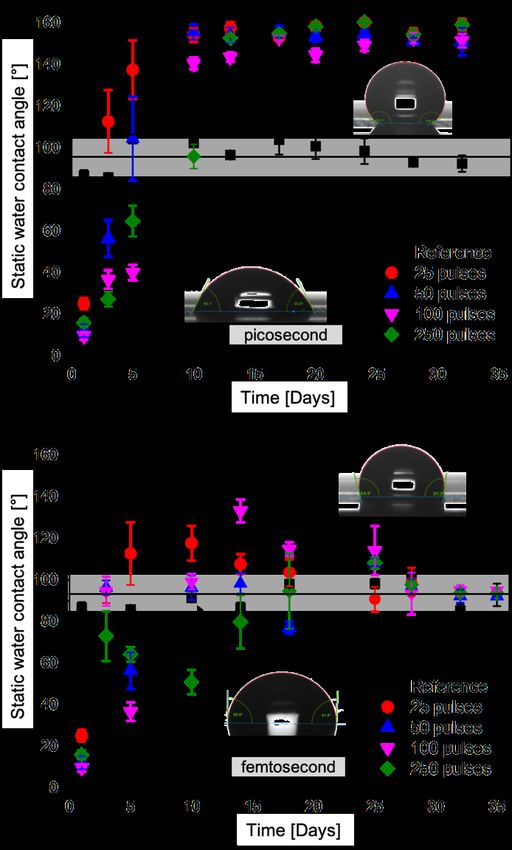
JLMN-Journal of Laser Micro/Nanoengineering Vol. 16, No. 1, 2021

and their wetting characteristic for a period of time of 35           beam quality of the applied fs laser source regarding the M²
days after processing.                                                was < 1.3 for a Gaussian beam profile and the laser radiation
                                                                      is linearly polarized with a polarization ratio > 100:1. The
2. Materials and methods                                              polarization direction at the optical systems’ input can be
2.1 Material                                                          random because it does not influence the interference inten-
    Plates of Aluminium clad (Al 2024) with lateral dimen-            sity profile due to a relatively small interference angle of
sions of 100 mm x 100 mm and 1 mm thickness were used                 15.6° [27].
in this study. The samples were electrolytically polished re-
sulting in an initial surface roughness of (Sq) of 41 nm ± 10         2.4 Surface characterization
nm. Before laser treatment the samples were cleaned from                  For the analysis of the surface topography and structure
contamination with isopropanol in an ultrasonic bath for 10           depth, a confocal microscope (Sensofar S Neox, Terrassa,
min at 22°C. Aluminum is naturally covered with an alumin-            Spain) with a 150x objective was used, providing vertical
ium oxide layer which is usually 20-30 nm thick [23,24].              and lateral resolution of 2 nm and 140 nm, respectively. The
                                                                      laser-treated substrates were also evaluated using a scanning
2.2 Picosecond DLIP                                                   electron microscope (ZEISS Supra 40 VP, Carl Zeiss Mi-
    Aluminium 2024 sheets were structured using a DLIP-               croscopy GmbH, Jena, Germany) at the operating voltage of
µFab workstation, developed by the TU Dresden and Fraun-              5.0 kV.
hofer IWS. It utilizes a solid-state 70 ps laser (neoLASE
GmbH, Hannover, Germany) emitting a 532 nm wavelength                 2.5 Wettability characterization
with a nominal output power of 2.7 W at a repetition rate of              The wettability of the patterned surface was analyzed
10 kHz resulting in laser fluence of 1.4 J/cm2. The beam              performing static water contact angle measurements over 35
quality of the applied ps laser source regarding the M²               days period with the drop shape analyzer (DSA 100 S, Krüss
was < 1.3 for a Gaussian beam profile and the laser radiation         GmbH, Hamburg, Germany), frequently measuring every
was linearly polarized with a polarization ratio > 100:1. For         three days. The tests were performed using 4 µl deionized
the fabrication of dot-like patterns, a four-beam DLIP was            water droplets at ambient conditions of 21 °C and 16% air
applied with a spatial period of 3.8 µm. The height of the            humidity. For the water contact angle measurement, the tan-
interference volume in which a periodic energy distribution           gent droplet fitting method was applied. Each measurement
is present was about 40 µm. A detailed description of the             was repeated at least five times for statistical purposes.
used setup was already published elsewhere [25].
                                                                      3. Results and discussion
2.3 Femtosecond DLIP                                                  3.1 Laser material processing
Femtosecond DLIP processing was performed using a work-                   The aluminium samples were structured using the four-
station, developed by the FTMC, ELAS Ltd. and Amplight                beam interference configuration with the fs and ps laser
KG in which high pulse energy femtosecond laser                       sources. In the case of the fs laser patterning, the interference
(200 fs – 10 ps, 1 kHz, 1030 nm, 14 mJ), provided by Am-              spot diameter formed by an optical imaging system was rel-
plight KG, can be managed. The optical setup consisted of a           atively large (2300 µm). Therefore, the maximum laser
diffractive optical element for beam splitting and a 4f lens          power was utilized to have the laser fluence (1.3 J/cm²) high
setup for the collection of separate beams. This setup pro-           enough to ablate the aluminium surface. Thereby, experi-
vides a simple way to overlap ultrashort laser pulses when            ments performed with the ps laser source were conducted
using the interference technique accurately and contains no           using the same laser fluence but with a smaller interference
dispersive elements, that can distort temporal (and spatial)          spot (45 µm in diameter). In addition, the number of laser
pulse characteristics [26]. Using the diffractive optical ele-        pulses per spot was varied between 25 and 250. The spots
ment from Holo/Or with a separation angle of 7.71°, the la-           were positioned in such a way that the patterned areas over-
ser beam was split into four beams (plus zero-order beam              lap only by 10%. The spatial period of the hole-like struc-
which was not used). This is the angle at which the beams             tures, which is described as the distance between the centers
are separated in after passing the DOE. By transmitting these         of two holes, was for both applied methods, ps and fs pro-
beams through the x2 magnification 4f lens setup, they are            cessing, constant 3.8 µm.
overlapped on the samples surface, that interfere at the angle            Because of the small overlap used (10%), there is no
of 15.6°, forming the interference period of 3.8 µm with the          need to carefully align the spots so that the ablated craters of
1030 nm wavelength. The pulse was stretched after passing             the overlapping areas are precisely superimposed with each
all optical elements resulting in in a constant pulse duration        other. The SEM micrograph of the structures fabricated with
of 400 fs at the sample surface. It was measured using Fre-           a low (50) and high (250) number of fs and ps pulses are
quency-Resolved Optical Gating Pulse Analyzer (FROG).                 shown in Fig. 1. The structures fabricated by four-beam
    The diameter of the interference spot, measured using a           DLIP consists of periodically distributed craters, ablated at
beam profiler camera at 1/e2 level, was 2.3 mm. However,              the interference intensity peaks. It has to be noted that the
the ablation threshold was exceeded in slightly smaller areas         interference spot exhibits a Gaussian intensity envelope,
with a diameter of approximately 2 mm. Considering the in-            which results in dissimilar structure heights, following the
terference angle (15.6°) and the diameter of the laser beams          intensity distribution. For allowing a comparison between
(2.3 mm) at the material’ surface, it is possible to calculate        the experiments, the micrographs were taken at the center of
the height of the interference volume, corresponding to               laser spots, where the peak intensity is the highest.
16.8 mm. On the sample surface, 1.3 J/cm2 fluence was
achieved using the maximal available pulse energy. The

                                                                 75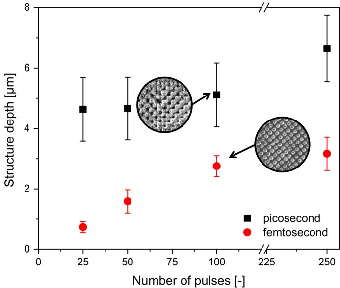
JLMN-Journal of Laser Micro/Nanoengineering Vol. 16, No. 1, 2021
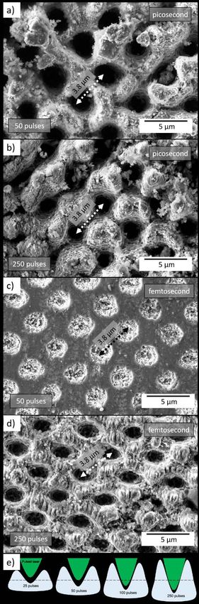
A first pronounced difference between the ps- and fs-pat-
terned structures is seen in Fig. 1a, and Fig. 1c, where the
structures fabricated at a low number of pulses are shown.
In the case of the fs patterning (Fig. 1c), the craters are al-
most perfectly round, having no rims around the edges.
However, in the case of ps pulses (Fig. 1a), not all craters
maintain their shapes, because of the irregular formation of
the rims, which surround them. Formation of the rims con-
firms the appearance of the melted material inside the abla-
tion zones (craters), which is redeposited around the craters
through Marangoni convection and recast pressure [28]. Be-
cause the molten material removed from the crater’s center
is brought on the surface of the untreated area between the
craters, it contributes highly to the final depth of the struc-
ture. For the picosecond pulsed structures, the morphologi-
cal appearance between 50 and 250 pulses (Fig.1a, b) is not
significantly different. In contrast, distinctly larger craters
are observed when the number of femtosecond pulses is in-
creased from 50 to 250 (Fig. 1d).
Also, the formation of the laser-induced periodic surface
structures (LIPSS) with a period of ~600 nm was observed
in the areas between the ablated craters. Since these struc-
tures are significantly smaller than the laser wavelength used,
they can be assigned to the classification of high spatial fre-
quency LIPSS [29]. In the case of ps laser-ablated structures,
the LIPSS features were not observed, possible due to the
big amount of recast material redeposited on the surface be-
tween the craters. Compared to previous studies where
LIPSS have been observed in aluminum using DLIP [11] or
direct laser writing with multi-pulse texturing [30,31], the
LIPSS features were observed for fluences between
0.10 J/cm2 and 0.17 J/cm2, which is significantly much
lower than the used fluence of 1.4 J/cm2 in our experi-
ments [32].
In addition to the surface morphology, Fig. 2 shows the
structure depth evolution as a function of the number of laser
pulses. The structure depth was measured using confocal mi-
croscopy, as described in the experimental section. It can be
seen that the structures fabricated with ps pulses are up to
2.2 times deeper than the fs-fabricated structures for 250
pulses (6.8 µm vs. 3.1 µm). This result can be explained by
the stronger melt ejection from the craters, which are ablated
using ps pulses, resulting in ridge formation [33]. Remarka-
bly, structure depth of 4.8 µm can be achieved using only 25
pulses in case of the ps laser source, whereas the topography
of the patterns created with the fs laser exhibit only 0.8 µm
in depth when using the same number of pulses.
Fig. 1 SEM images of hole-like microstructures with a spa-
tial period of 3.8 µm on aluminium 2024 irradiated with 532 nm
wavelength, a pulse duration of 70 ps, 10 kHz repetition rate and
laser fluence of 1.4 J/cm2 (a, b) and with 1030 nm wavelength, a
pulse duration of 400 fs (c, d) 1 kHz repetition rate and laser flu-
ence of 1.3 J/cm2 applying 50 pulses (a, c) and 250 pulses (b, d).
The scheme in (e) illustrates the pile-ups of the material with an
increasing number of pulses relative to the origin surface (dashed
line).
76JLMN-Journal of Laser Micro/Nanoengineering Vol. 16, No. 1, 2021
Fig. 2 Structure depth as a function of the number of used
pulses for 70 ps (black) and 400 fs (red) irradiation. The circular
insets depict the exemplarily micro-structured surface patterned
with 100 pulses.
3.2 Long-term wetting studies
After laser processing, the wetting characteristic of the
fabricated microstructures was analyzed by means of static
water contact angle (WCA) measurements over a period of
35 days. The resulting evolution is presented in Fig 3.
The WCA of the untreated surface reference stays at a
level between 88° and 104° (grey bar). Immediately after the
laser processes (day 1-3), the structures showed a hydro-
philic condition, expressed by a WCA under 90°, inde-
pendently of the applied pulse duration or number of pulses.
Mainly responsible for this behavior are unsaturated alumi-
num and oxygen atoms leading to a hydrophilic condition,
which has already been reported in other works [34,35]. Fig. 3 Static water contact angle (WCA) measurements as a
In the following, the WCA for all picosecond-treated sub- function of time after laser processing, measured with deionized
strates was constantly rising with time up to superhydropho- water droplets of 4 µl volume for the structures fabricated with
bic (WCA > 150°) condition after 16 days, where it re- 25, 50, 100, 250 pulses, for picosecond (a) and femtosecond (b)
mained constant until day 32. Furthermore, no significant pulse durations. The photographic insets represent typical appear-
differences were observed regarding the final static contact ances of the droplet shape.
angles among the surfaces fabricated using different num-
bers of ps pulses (Fig. 3a). In addition, the microstructures This state is most likely to be achieved when the struc-
fabricated with 250 pulses, featured with the largest struc- ture has a high aspect ratio. Furthermore, the temperature of
ture depth of 6.8 µm, presented in all measurements of the the environment, the surface tension of the liquid used for
last 16 days the highest WCA. A surface texture with a min- the droplets and the surface chemistry influence the wetting
imum depth of 4.7 µm is primarily responsible for the super- state [38,39]. It was also shown that a texturing with a pat-
hydrophobic characteristic since the minimum roughness for tern in the hundred µm range produces a more hydrophobic
an increasing wetting state is existing. Moreover, due to the surface despite micrometer deep structures [31]. However, a
symmetrical patterning, hence the systematic formation of utterly superhydrophobic property has so far only been
laser-induced melt residues, the fabricated texture provides achieved with significantly smaller structures or by addi-
a controllable roughness, which specifically determines the tional chemical treatment [40].
wetting behavior [11,36]. The required minimum roughness In contrast, the femtosecond-processed samples showed
was fabricated only by using picosecond pulsed irradiation. a similar rising trend but reaching a maximal WCA of 131°
DLIP structures on a surface allow a homogeneous and uni- after 14 days. However, this trend did not stay constant after
form modification of a topography, which allows a constant 25 days. The WCA of all structures dropped down to 92°,
functionality concerning the structure. When wetting sur- which is very similar to the wetting state of the untreated
faces, the aspect ratio of the textures has an indirect influ- reference. No clear trend could be seen, independently of the
ence. In order to achieve a superhydrophobic condition, a applied number of pulses (Fig. 3b).
Cassie-Baxter wetting is aspired, where a single droplet is It is known that the wetting characteristic of a surface is de-
exclusively in contact with the roughness peaks of a topog- fined by two influencing factors: The surface chemistry and
raphy [17,37]. the roughness, which is expressed in this study by the struc-
ture depth. The chemistry is not considered in this case since
77JLMN-Journal of Laser Micro/Nanoengineering Vol. 16, No. 1, 2021
it is well known that carbon from the ambient air is accumu- with a structure depth up to 6.8 µm, which finally, developed
lated subsequently on aluminium that has been irradiated a constant superhydrophobic characteristic with water con-
with the laser. This carbon content then increases the number tact angles above 150° after 16 days. This is consistent with
of non-polar sites on the surface, which leads to an increase the current state of the art. According to that, an increased
of the static water contact angle. In combination with a sur- roughness or texture depth contributes to the superhydro-
face texture, it results in a constant superhydrophobic char- phobic Cassie-Baxter condition. This roughness was created
acteristic [12,41]. This effect is dominant in ns and ps laser by the ps texturing due to the strong redeposition of the re-
treatment [20,42,43]. On the other hand, it is well known cast material. Contrarily, for the fs treated samples, the lim-
that an increase of aluminium oxide, formed due to laser pro- ited structure depth of 3.1 µm and the compensating chemi-
cessing, is responsible for a large number of polar-sites on cal processes on the surface did not lead to a significant
the surface. These unsaturated aluminium and oxygen atoms change of the wetting behavior in the long-term observation.
can be responsible for the decrease of the maximum WCA
of 131° after 14 days, leading to a hydrophilic condi- Acknowledgments
tion [35,44,45] (Fig. 3b). This work was carried out in the framework of the Reinhart
In the fs section of this study, the maximum structure depths Koselleck project (323477257), which has received funding
of 3.1 µm and the slightly more dominant aluminium oxide from the German Research Foundation (German: Deutsche
deposition on the surface lead to an approximation to the ref- Forschungsgemeinschaft DFG). The work of A.L. is also
erence wetting state with a WCA of 93° after 35 days supported by the German Research Foundation (DFG) under
(Fig. 3b). It was also reported, that fs processed aluminium the Excellence Initiative program by the German federal and
substrates reached a constant superhydrophobic condition, if state government to promote top-level research at German
their topography fulfilled a certain minimum roughness [46– universities. The work of B.V. and S.I. was carried out in the
49]. Furthermore, it is the state of the art that a nano rough- framework of SLAM-HELP project, which was supported
ness alone can make a surface more hydrophobic, but not by EUREKA and the European Commission under the Eu-
superhydrophobic [50]. This is achieved either by an addi- rostars program.
tional micro-roughness or by applying further silane-based
solution. Such coating reduces the surface free energy and References
thus the wetting of water, and therefore it increases the water [1] M. Okoshi, Y. Awaihara, T. Yamashita, and N. In-
contact angle [51]. oue: Mater. Lett., 139, (2015) 300.
The chemical phenomena on a laser-treated Aluminium [2] X. Zhang, F. Shi, J. Niu, Y. Jiang, and Z. Wang: J.
surface have already been investigated in detail in the past Mater. Chem., 18, (2008) 621.
and are summarized briefly below, both for ps and fs treat- [3] S. Li, K. Page, S. Sathasivam, F. Heale, G. He, Y.
ment. For example, a micro-nanostructure with a roughness Lu, Y. Lai, G. Chen, C. J. Carmalt, and I. P. Parkin:
of up to 5.2 µm was generated on pure aluminium (99.9% J. Mater. Chem., A6, (2018) 17633.
purity) by means of 10 ps irradiation. XPS was used to detect [4] L. Gao, W. Zhou, Y. Wang, S. Wang, C. Bai, S. Li,
an increased occurrence of non-polar groups, which were re- B. Liu, J. Wang, and Y. L. Li: Optik, 127, (2016)
sponsible for a final water contact angle of up to 153° [20]. 5211.
Similar results were reported for line-like structures on the [5] E. Williams, E. B. Brousseau, and A. Rees: Int. J.
alloy Al 5052, which were produced with 500 ps radiation. Adv. Manuf. Technol., 74, (2014) 769.
The up to 66 µm deep structures contained C on the surface, [6] B. Voisiat, M. Gedvilas, S. Indrišiūnas, and G.
which indicates carboxylic acids as demonstrated by EDX Račiukaitis: Physcs. Proc., 12, (2011) 116.
and XPS analysis [52]. Liu et al. also showed that fs irradia- [7] S. Alamri, B. Krupop, T. Steege, A. Aguilar-
tion on Aluminium after 60 days leads to an increase in the Morales, V. Lang, S. Storm, F. Schell, C. Zwahr, C.
C/Al atomic ratio at the surface and thus to a superhydro- Kracht, M. Bieda, B. Voisiat, U. Klotzbach, A. F.
phobic characteristic. However, this is only the case if the Lasagni, and T. Kunze: Proc. SPIE, Vol. 10906,
corresponding topography exceeds a minimum roughness of (2019) 109060S.
several µm [49]. Different wetting states exhibiting in the [8] S. Indrisiunas, B. Voisiat, A. Žukauskas, and G.
first 17 days on fs processed samples, could be a result of Račiukaitis: Proc SPIE, Vol. 9350, (2015) 935003.
short-term change in surface chemistry. However, for a long- [9] D. Sola, C. Lavieja, A. Orera, and M. J. Clemente:
term transition into the superhydrophobic regime, a topog- Opt. Laser Eng., 106, (2018)139.
raphy with a significantly increased roughness is required, [10] A. Rosenkranz, M. Hans, C. Gachot, A. Thome, S.
as in the case of ps fabricated structures. Bonk, and F. Mücklich: Lubricants, 4, (2016) 2.
[11] S. Milles, B. Voisiat, M. Nitschke, and A. F. Lasa-
4 Conclusion gni: J. Mater. Process. Tech., 270, (2019) 142.
In the present study, the influence of pico- and femtosec- [12] S. Milles, M. Soldera, B. Voisiat, and A. F. Lasagni:
ond irradiation on the DLIP process of aluminium 2024 was Sci. Rep., 9, (2019) 1.
studied. The resulting microstructures were fabricated em- [13] S. Milles, M. Soldera, T. Kuntze, and A. F. Lasagni:
ploying four-beam DLIP setup and investigated regarding Appl. Surf. Sci., 525, (2020) 146518.
their surface topography and their wetting properties. It was [14] J. T. Cardoso, A. I. Aguilar-Morales, S. Alamri, D.
shown that the ultra-fine ablation is dominant for both pulse Huerta-Murillo, F. Cordovilla, A. F. Lasagni, and J.
duration regimes. Femtosecond irradiation is suitable for L. Ocaña: Opt. Las. Eng., 111, (2018) 193.
precise structures with a maximum depth of 3.1 µm, while [15] D. Huerta-Murillo, A. García-Girón, J. M. Romano,
picosecond irradiation allows fabricating microstructures J. T. Cardoso, F. Cordovilla, M. Walker, S. S.
78JLMN-Journal of Laser Micro/Nanoengineering Vol. 16, No. 1, 2021
Dimov, and J. L. Ocaña: Appl. Surf. Sci., 463, [41] A.-M. Kietzig, S. G. Hatzikiriakos, and P. Englezos:
(2019) 838. Langmuir, 25, (2009) 4821.
[16] B. Bhushan: “Surface Roughness Analysis and [42] L. R. de Lara, R. Jagdheesh, and J. L. Ocaña: Mater.
Measurement Techniques” ed. by CRC Press (Bhu- Lett., 184, (2016) 100.
shan, Boca Raton, 2000) p.1760. [43] Z. Lu, P. Wang, and D. Zhang: Corros. Sci., 91,
[17] A. B. D. Cassie and S. Baxter: Trans. Faraday Soc., (2015) 287.
40, (1944) 546. [44] G. Azimi, R. Dhiman, H.-M. Kwon, A. T. Paxson,
[18] R. N. Wenzel: Ind. Eng. Chem., 28, (1936) 988. and K. K. Varanasi: Nat. Mater., 12, (2013) 315.
[19] J. Bonse, S. V. Kirner, M. Griepentrog, D. [45] M. M. Gentleman and J. A. Ruud: Langmuir, 26,
Spaltmann, and J. Krüger: Materials, 11, (2018) 5. (2010) 1408.
[20] J. Long, M. Zhong, H. Zhang, and P. Fan: J. Colloid [46] A.-M. Kietzig, M. N. Mirvakili, S. Kamal, P.
Interface Sci., 441, (2015) 1. Englezos, and S. G. Hatzikiriakos: J. Adhes. Sci.
[21] A. Samanta, Q. Wang, S. K. Shaw, and H. Ding: Ma- Technol., 25, (2011) 2789.
ter. Design, 192, (2020) 108744. [47] P. Bizi-bandoki, S. Valette, E. Audouard, and S. Be-
[22] M. Gedvilas, S. Indrišiūnas, B. Voisiat, E. nayoun: Appl. Surf. Sci., 273, (2013) 399.
Stankevičius, A. Selskis, and G. Račiukaitis: Phys. [48] P. Bizi-Bandoki, S. Benayoun, S. Valette, B.
Chem. Chem. Phys., 20, (2018) 12166. Beaugiraud, and E. Audouard: Appl. Surf. Sci., 257,
[23] I. Pires, L. Quintino, C. M. Rangel, G. E. Thompson, (2011) 5213.
P. Sheldon, and X. Zhou: Int. J. Surf. Sci. Eng., 78, [49] W. Liu, M. Cai, X. Luo, C. Chen, R. Pan, H. Zhang,
(2000) 179. and M. Zhong: J. Laser Appl., 31, (2019) 022503.
[24] J. M. Holt, H. Mindlin, C. Y. Ho: “Structural Alloys [50] L. Orazi, I. Gnilitskyi, and A. P. Serro: J. Micro
Handbook” ed. by J. M. Holt, H. Mindlin, C. Y. Ho, Nano-Manuf., 5, (2017) 021008.
(CINDAS/Purdue University, West Lafayette, 1997) [51] A. I. Gavrilov, D. V. Golovin, A. M. Emelyanenko,
p.1-2500. D. A. Zayarny, A. A. Ionin, S. I. Kudryashov, S. V.
[25] S. Eckhardt, M. Siebold, and A. F. Lasagni: Opt. Ex- Makarov, P. N. Saltuganov, and L. B. Boinovich:
press, 24, (2016) 553. Bull. Russ. Acad. Sci. Phys., 80, (2016) 358.
[26] A. A. Maznev, T. F. Crimmins, and K. A. Nelson: [52] W. Xing, Z. Li, H. Yang, X. Li, X. Wang, and N. Li:
Opt. Lett., 23, (1998) 1378. Mater. Design, 183, (2019) 108156.
[27] S. Indrisiunas, B. Voisiat, M. Gedvilas, and G.
Račiukaitis: Proc. LPM 2017, (2017) 1–5.
[28] A. I. Aguilar-Morales, S. Alamri, T. Kunze, and A.
F. Lasagni: Opt. Laser Technol., 107, (2018) 216.
[29] M. Mezera and G. R. B. E. Römer: Opt. Express, 27, (Received: May 28, 2020, Accepted: March 14, 2021)
(2019) 6012.
[30] J. I. Ahuir-Torres, M. A. Arenas, W. Perrie, and J. de
Damborenea: Opt. Las. Eng., 103, (2018) 100.
[31] J. I. Ahuir-Torres, M. A. Arenas, W. Perrie, G.
Dearden, and J. de Damborenea: Surf. Coat. Tech.,
321, (2017) 279.
[32] P. Hauschwitz, D. Jochcová, R. Jagdheesh, D. Rosto-
har, J. Brajer, J. Kopeček, M. Cimrman, M. Smrž, T.
Mocek, and A. Lucianetti: Opt. Laser Technol., 133,
(2021) 106532.
[33] B. Voisiat, C. Zwahr, and A. F. Lasagni: Appl. Surf.
Sci., 471, (2019) 1065.
[34] E. Louvis, P. Fox, and C. J. Sutcliffe: J. Mater. Proc.
Tech., 211, (2011) 275.
[35] R. Jagdheesh, M. Diaz, and J. L. Ocaña: RSC Adv.,
6, (2016) 72933.
[36] R. Baumann, S. Milles, B. Leupolt, S. Kleber, J.
Dahms, and A. F. Lasagni: Opt. Las. Eng., 137,
(2021) 106364.
[37] A. Giacomello, M. Chinappi, S. Meloni, and C. M.
Casciola: Phys. Rev. Lett., 109, (2012) 226102.
[38] B. Bhushan and Y. C. Jung: J. Phys. Condens. Mat.
20, (2008) 225010.
[39] A. Marmur: Ann. Rev. Mater. Res., 39, (2009) 473.
[40] V. Vercillo, J. T. Cardoso, D. Huerta-Murillo, S.
Tonnicchia, A. Laroche, J. A. Mayén Guillén, J. L.
Ocaña, A. F. Lasagni, and E. Bonaccurso: Mater.
Lett., 3, (2019) 100021.
79You can also read