What Camera Motion Reveals About Shape With Unknown BRDF
←
→
Page content transcription
If your browser does not render page correctly, please read the page content below
What Camera Motion Reveals About Shape With Unknown BRDF

                                                Manmohan Chandraker
                                            NEC Labs America, Cupertino, CA

                          Abstract                                    We begin in Sec. 3 by proposing a differential stereo rela-
    Psychophysical studies show motion cues inform about           tion that relates depth to camera motion, while accounting for
shape even with unknown reflectance. Recent works in com-          general material behavior in the form of an isotropic BRDF.
puter vision have considered shape recovery for an object of       Diffuse photoconsistency of traditional Lambertian stereo fol-
unknown BRDF using light source or object motions. This            lows as a special case. Surprisingly, it can be shown that
paper addresses the remaining problem of determining shape         considering a sequence of motions allows eliminating the
from the (small or differential) motion of the camera, for         BRDF dependence of differential stereo.
unknown isotropic BRDFs. Our theory derives a differen-               The mathematical basis for differential stereo is outwardly
tial stereo relation that relates camera motion to depth of        similar to differential flow for object motion [4]. However,
a surface with unknown isotropic BRDF, which generalizes           while BRDFs are considered black-box functions in [4], our
traditional Lambertian assumptions. Under orthographic pro-        analysis explicitly considers the angular dependencies of
jection, we show shape may not be constrained in general, but      isotropic BRDFs to derive additional insights. A particu-
two motions suffice to yield an invariant for several restricted   lar benefit is to show that ambiguities exist for the case of
(still unknown) BRDFs exhibited by common materials. For           camera motion, which render shape recovery more difficult.
the perspective case, we show that three differential motions         Consequently, for orthographic projection, Sec. 4 shows a
suffice to yield surface depth for unknown isotropic BRDF and      negative result whereby constraints on the shape of a surface
unknown directional lighting, while additional constraints are     with general isotropic BRDF may not be derived using camera
obtained with restrictions on BRDF or lighting. The limits         motion as a cue. But we show the existence of an orthographic
imposed by our theory are intrinsic to the shape recovery          invariant for several restricted isotropic BRDFs, exhibited
problem and independent of choice of reconstruction method.        by common materials like plastics, metals, some paints and
We outline with experiments how potential reconstruction           fabrics. The invariant is characterized as a quasilinear partial
methods may exploit our theory. We illustrate trends shared        differential equation (PDE), which specifies the topological
by theories on shape from motion of light, object or camera,       class up to which reconstruction may be performed.
relating reconstruction hardness to imaging complexity.               Under perspective projection, Sec. 5 shows that depth for
                                                                   a surface with unknown isotropic BRDF, under unknown di-
                                                                   rectional lighting, may be obtained using differential stereo
1. Introduction                                                    relations from three or more camera motions. Further, we
   Image formation is an outcome of the interaction between        show that an additional linear constraint on the surface gra-
shape, lighting and camera, governed by material reflectance.      dient is available for the above restricted families of BRDFs.
Motion of the object, light source or camera are important         These results substantially generalize Lambertian stereo, since
cues for recovering object shape from images. Each of those        depth information is obtained without assuming diffuse photo-
cues have been extensively studied in computer vision, under       consistency, while a weak assumption on material type yields
the umbrellas of optical flow for object motion [7, 9], pho-       even richer surface information. Table 1 summarizes the main
tometric stereo for light source motion [19] and multiview         theoretical results of this paper.
stereo for motion of the camera [15]. Due to the complex              Finally, Sec. 6 explores relationships between differential
and often unknown nature of the bidirectional reflectance          theories pertaining to motion of the object, light source or cam-
distribution function (BRDF) that determines material behav-       era. We discuss their shared traits that allow shape recovery
ior, simplifying assumptions like brightness constancy and         and common trends relating hardness of surface reconstruc-
Lambertian reflectance are often employed.                         tion to complexity of imaging setup. Those perspectives on
   However, psychophysical studies have established that           shape from motion are summarized in Table 2.
complex reflectance does not impede shape perception [16].
Correspondingly, recent works in computer vision show that         2. Related Work
differential motion of the light source [2] or the object [4]         Relating shape to intensity variations due to differential
inform about shape even with unknown BRDFs. This paper             motion has a significant history in computer vision, dating to
solves the remaining problem of characterizing shape recovery      studies in optical flow [7, 9]. The limitations of the Lamber-
for unknown BRDFs, using differential motion of the camera.        tian assumption have been recognized by early works [11, 18].
Camera Light BRDF #Motions Surface Constraint Shape Recovery Theory
Persp. Unknown Lambertian 1 Linear eqn. Depth Stereo
Orth. Unknown General, unknown - Ambiguous for reconstruction Prop. 3
Orth. Unknown View-angle, unknown 2 Homog. quasilinear PDE Level curves Rem. 1, Prop. 6
Orth. Known Half-angle, unknown 2 Inhomog. quasilinear PDE Char. curves Props. 4, 7
Persp. Unknown General, unknown 3 Linear eqn. Depth Prop. 8
Persp. Unknown View-angle, unknown 3 Lin. eqn. + Homog. lin. PDE Depth + Gradient Sec. 5.2
Persp. Known Half-angle, unknown 3 Lin. eqn. + Inhomog. lin. PDE Depth + Gradient Prop. 9
Table 1. Summary of main results of this paper. Note that k camera motions result in k + 1 images. BRDF is described by angular dependences
and functional form. In general, more constrained BRDF or lighting yields richer shape information. Also, see discussion in Sec. 6.
Several stereo methods have been developed for non- Let the focal length of the camera be f . The camera model
Lambertian materials. Zickler et al. exploit Helmholtz reci- is perspective for finite values of f and approaches ortho-
procity for reconstruction with arbitrary BRDFs [20]. Refer- graphic as f → ∞. The principal point on the image plane
ence shapes of known geometry and various material types is defined as the origin of the 3D coordinate system, with the
are used in example-based methods [17]. Savarese et al. study camera center at (0, 0, −f )> . Denoting β = f −1 , a 3D point
stereo reconstructions for specular surfaces [14]. In contrast, x = (x, y, z)> is imaged at u = (u, v)> , where
this paper explores how an image sequence derived from
(1 + βz)u = x , (1 + βz)v = y. (1)
camera motion informs about shape with unknown isotropic
BRDFs, regardless of reconstruction method. Motion field Let the camera undergo a rigid body rotation
Light source and object motions have also been used to R
e and translation τe. We equivalently assume that the object
understand shape with unknown BRDFs. Photometric stereo and light source undergo a rotation R = R e −1 and translation
−1
based on small light source motions is presented by [5], while τ =R e τe, with a fixed camera. For differential motion, we
generalized notions of optical flow are considered in [6, 12]. approximate R ≈ I + [ω]× , where ω = (ω1 , ω2 , ω3 )> .
An isometric relationship between changes in normals and The motion field, µ = (u̇, v̇)> , is the differential motion
radiance profiles under varying light source is used by Sato et of the image obtained by differentiating (1). We refer the
al. to recover shape with unknown reflectance [13]. reader to prior works like [11, 4] for a derivation and simply
Closely related to this paper are the works of Chandraker et express the motion field here in a form similar to [4]:
al. that derive topological classes up to which reconstruction >
can be performed for unknown BRDFs, using differential mo- α2 + ω2 z α4 − ω1 z
Perspective: µ = α1 + , α3 + , (2)
tion of the source [2] or object [4]. This paper derives limits 1 + βz 1 + βz
on shape recovery using the third cue, namely camera motion. >
Orthographic: µ = (α5 + ω2 z, α6 − ω1 z) , (3)
The similarities and differences between the frameworks are
explored throughout this paper and summarized in Sec. 6. where αi , i = 1, · · · , 6, are known functions of ω, τ , u and
β, whose algebraic forms are shown in [1].
3. Differential Stereo for General BRDFs
Differential stereo relation Let s be the light source direc-
In this section, we state our assumptions and derive the tion and v = (0, 0, −1)> be the camera direction. For a 3D
relationship between camera motion and surface depth, for un- point x = (x, y, z(x, y))> on the surface, the unit normal is
known isotropic BRDFs. We also provide some intuition into
1
that relationship, which will be used for subsequent shape re- n = (n1 , n2 , n3 )> = (zx2 + zy2 + 1)− 2 (zx , zy , −1)> , (4)
covery results. To facilitate presentation, we will occasionally
point the reader to an extended version [1] for details. where ∇z = (zx , zy )> is the surface gradient. For a homoge-
neous isotropic BRDF ρ, with distant light source, the image
3.1. Derivation of the Differential Stereo Relation intensity at pixel u of a 3D point x is assumed to be
Assumptions and setup We assume static object and light-
I(u, t) = σ(x)ρ(x, n, s, v), (5)
ing, while the camera moves. For rigid body motion, our
analysis equivalently considers a fixed camera, with the ob- where σ is the albedo and the cosine fall-off is absorbed in ρ.
ject and light source undergoing the inverse motion. The This is a reasonable imaging model that subsumes traditional
illumination is assumed directional and distant. The object ones like Lambertian and allows general isotropic BRDFs
BRDF is assumed to be homogeneous and isotropic, with modulated by spatially varying albedo. We do not make any
unknown functional form. We make a technical assumption assumptions on the functional form of ρ, except smoothness.
that the camera direction is constant over the entire object. 1 Taking the total derivative on both sides of (5), we get
Global illumination effects are assumed negligible.
d dσ
1 Thisassumption is exact for orthographic cameras, but only an approx-
Iu u̇ + Iv v̇ + It = σ ρ(x, n, s, v) + ρ . (6)
dt dt
imation for perspective projection where viewing direction may vary over
object dimensions. The approximation is reasonable in practical situations Since σ is intrinsically defined on the surface coordinates,
where the camera is not too close to the object, relative to object size. its total derivative vanishes. For the rigid body motion weconsider, ṅ = ω × n and ṡ = ω × s, while the camera (∇u E)> µ + Et = ω > π. (11)
direction remains unchanged. Using chain rule differentiation
The entity π is central to our theory, since it captures the
and noting that µ = (u̇, v̇)> is the motion field, we have
dependence of differential stereo on BRDF. Its practical sig-
(∇u I)> µ + It = σ [ (∇x ρ)> ν + (∇n ρ)> (ω × n) nificance is that any shape recovery method that seeks invari-
ance to material behavior must either accurately model π, or
+ (∇s ρ)> (ω × s) ] , (7)
eliminate it. Our work adopts the latter approach.
where ν = ẋ is the linear velocity. While the above discussion This definition of π leads to an observation intrinsic to
gives intuition for the differential relation in (7), we refer the shape recovery with isotropic BRDFs:
reader to [1] for a rigorous derivation.
Proposition 1. The BRDF dependence of differential stereo is
For distant lighting and homogeneous reflectance in our
captured by a 2D vector in the principal plane of the camera.
setup, we may assume that ∇x ρ is negligible. Further, divid-
ing the two sides of (7) with those of (5), we get Proof. Since an isotropic BRDF depends on the three angles
between normal, camera and light directions, we may write
(∇u E)> µ + Et = (n × ∇n log ρ + s × ∇s log ρ)> ω (8)
ρ̃(n> s, s> v, n> v) = log ρ(n, s, v). (12)
where we use the notation E = log I and the identities Denote θ = n> s, φ = s> v and ψ = n> v. Then, applying
(∇a ρ)> (ω × a) = (a × ∇a ρ)> ω and ∇a log ρ = ρ−1 ∇a ρ, chain-rule differentiation, we may write (10) as
for some a ∈ R3 . We call (8) the differential stereo relation.
π = n × ∇n ρ̃ + s × ∇s ρ̃
3.2. Understanding the Differential Stereo Relation = ρ̃θ (n × s) + ρ̃ψ (n × v) + ρ̃θ (s × n) + ρ̃φ (s × v)
Generalization of Lambertian stereo Initial intuition into = ρ̃ψ (n × v) + ρ̃φ (s × v). (13)
the differential stereo relation of (8) may be derived by noting
how it generalizes traditional Lambertian stereo. For two From the form of π in (13), it is evident that π > v = 0. For
images I 1 and I 2 related by a known motion, Lambertian our choice of coordinate system, v = (0, 0, −1)> . Thus,
stereo seeks the depth z that best satisfies brightness con- π3 = 0. (14)
stancy: I 1 (u) = I 2 (u + µ(z)). Substituting a Lambertian
reflectance ρ(n, s, v) = n> s in (8), we get It follows that the BRDF-dependent entity π = (π1 , π2 , 0)>
> lies on the principal plane of the camera.
(∇u E)> µ + Et = n × (n> s)−1 s + s × (n> s)−1 n ω
This is an important result that limits the extent to which
= 0> ω = 0, (9) shape may be recovered from differential stereo. The follow-
ing sections explore the precise nature of those limits.
which is precisely brightness constancy (total derivative of im-
age intensity is zero). Thus, diffuse photoconsistency imposed 4. Orthographic Projection
by traditional stereo is a special case of our theory.
Estimating the motion field, µ, is equivalent to determin-
Relation to object motion For object motion, a differential ing dense correspondence and thereby, object shape. In this
flow relation is derived in [4]. The differential stereo relation section, we consider shape recovery with unknown BRDF un-
of (8) has an additional dependence on BRDF derivatives der orthographic projection, using a sequence of differential
with respect to the light source. This stands to reason, since motions. Our focus will continue to be on providing intuitions,
both the object and lighting move relative to camera in the while refering the reader to [1] for details.
case of camera motion, while only the object moves in the
case of object motion. Thus, intuitively, camera motion leads 4.1. Rank Deficiency and Depth Ambiguities
to a harder reconstruction problem. Indeed, as we will see
It is clear that just one differential motion of the camera is
next, the dependence of (8) on lighting leads to a somewhat
insufficient to extract depth, since (11) is a linear relation in
surprising additional ambiguity.
the multiple unknowns {z, π}. Consequently, we consider a
Ambiguity for camera motion Now we derive some addi- sequence of differential motions. We start by observing that,
tional insights by making a crucial departure from the anal- in the case of orthography, a rank deficiency similar to the
ysis of [4]. Namely, instead of treating isotropic BRDFs as case of object motion exists for camera motion too.
entirely black box functions, we explicitly consider their phys- Under orthography, the motion field µ is given by (3).
ical property in the form of angular dependencies between the Noting the µ1 and µ2 are linear in z, we observe that the
normal, light source and camera directions. We define differential stereo relation of (11) reduces to:
π = n × ∇n log ρ + s × ∇s log ρ, (10) pz + q = ω > π (15)
which allows rewriting the differential stereo relation (8) as: where, using (3), p and q are known entities given byp = ω2 Eu − ω1 Ev (16) The above is an example of the comparative limits on shape
q = α5 Eu + α6 Ev + Et . (17) recovery with object or camera motion. For object motion,
only the relative motion between camera and object must be
Consider m > 0 differential motions of the camera about accounted. Thus, the definition of π = n × ∇n log ρ in [4]
a base position, given by {ω i , τ i }, for i = 1, · · · , m. Let depends only on the BRDF-derivative with respect to surface
E 0 = log I 0 be the logarithm of the base image, with E i normal. For camera motion, both object and lighting move
being the log-image for each motion {ω i , τ i }. Note that the relative to the camera. Additional dependence of π in (10) on
spatial gradient of the image is independent of motion and BRDF-derivative with respect to lighting makes it indetermi-
corresponds to the derivative of E 0 with respect to u. We nate without further restrictions on BRDF or lighting.
will simply denote it as ∇u E = (Eu , Ev )> . The temporal While Prop. 3 is a negative result, its development pro-
derivative, Et , as well as p and q, depend on the motion. vides valuable insight. An m × 3 rank-deficient matrix Ã
To recover the unknown depth z, an initial approach may constructed using m differential motions, for any m ≥ 2,
consider m ≥ 3 relations of the form (11) as a linear system: determines γ = Ã+ q. From (14), (20) and (21), it follows:
−p1 ω11 ω21 Corollary 1. Under orthography, two differential motions of
z
the camera suffice to constrain π to a linear relation in z.
à π1 = q, with à = ... .. , (18)
.
π2 −pm ω m ω m This fact will now be used, along with some restrictions
1 2
on the BRDF, to derive BRDF-invariant constraints on depth.
where q = (q 1 , · · · , q m )> . Note that Proposition 1 allows
us to drop any dependence on ω3 , since π3 = 0 is not an 4.2. BRDF-Invariance for Certain Material Types
unknown. But observe the form of pi = ω2i Eu − ω1i Ev from The result of Prop. 3 immediately suggests a possibility to
(16), which makes à rank-deficient. Thus, we have shown: constrain z: consider a BRDF whose dependence on ψ and φ
is restricted in a way that introduces a constraint on π. Note
Proposition 2. Under orthographic projection, surface depth
that the functional form of the BRDF, ρ(·), remains unknown.
under unknown BRDF may not be unambiguously recovered
using solely camera motion as the cue.
4.2.1 BRDFs Dependent on View Angle
While depth cannot be directly recovered from differential
Some reflectances depend on the angles subtended by the
stereo under orthography, a natural next step is to consider
normal on the source and view directions. Such BRDFs can
the possibility of any constraints on the depth. However, the
explain the darkening near image edges for materials like
result of Proposition 1 makes this challenging for the case
fabrics. Another well-known example is the Minnaert BRDF
of camera motion. To see this, we note that the null vector
for lunar reflectance [10]. In such cases, we may define
of the rank-deficient matrix à is (1, −Ev , Eu )> . With Ã+
denoting the Moore-Penrose pseudoinverse of Ã, for any ρ̄(n> s, n> v) = log ρ(n, s, v). (22)
k 6= 0, we have a parameterized solution to (18): > >
Again denoting θ = n s and ψ = n v, we get from (10):
z 1 π = n × ∇n ρ̄ + s × ∇s ρ̄
π1 = γ + k −Ev , (19) = n × (ρ̄θ s + ρ̄ψ v) + s × ρ̄θ n = ρ̄ψ n × v. (23)
π2 Eu
Noting that n × v = (−n2 , n1 , 0)> , one may eliminate the
> +
where γ = (γ1 , γ2 , γ3 ) = Ã q. From the first equation in BRDF-dependent term ρ̄ψ using (20) and (21) to obtain a
the above system, we have k = z − γ1 . Thereby, we get the relationship between depths and normals:
following two relations between z and π: π1 −n2 (γ2 + Ev γ1 ) − Ev z
= = . (24)
π1 = (γ2 + Ev γ1 ) − Ev z (20) π2 n1 (γ3 − Eu γ1 ) + Eu z
π2 = (γ3 − Eu γ1 ) + Eu z (21) Using (4) to relate the normal to the gradient, this reduces to
Now, any relationship between π1 and π2 gives a constraint [(γ2 + Ev γ1 ) − Ev z]zx + [(γ3 − Eu γ1 ) + Eu z]zy = 0, (25)
on the depth, z. But from Prop. 1, π is an arbitrary vector in which is a constraint on surface depth and gradient that is
the principal plane. That is, from (13), π1 and π2 depend on independent of both the BRDF and lighting. We note that
two unknown BRDF derivatives ρ̃ψ and ρ̃φ . It follows that m ≥ 2 differential motions of the camera suffice to determine
without imposing any external constraint on ρ̃ψ and ρ̃φ , one γ from (19) and yield the constraint in (25). Thus, we state:
may not derive a constraint on surface depth. Thus, we state:
Remark 1. Under orthography, for a BRDF of unknown
Proposition 3. Under orthographic projection, for unknown functional form that depends on light and view directions, two
isotropic BRDF, an unambiguous constraint on surface depth differential motions of the camera suffice to yield a constraint
may not be derived using solely camera motion as the cue. on surface depth independent of BRDF and lighting.4.2.2 BRDFs Dependent on Half-angle 4.2.3 Dependence on Arbitrary Angle in {s, v}-Plane
For many common materials like metals or plastics, it is Recent works on empirical analysis of measured BRDFs show
reasonable to assume that reflectance depends on the angle that reflectance functions often depend on the angles the sur-
between the surface normal and the half-angle between the face normal makes with the light source and another direction
source and view directions. For a surface of such material in the plane defined by the source and camera directions [3].
type, we can show that a sequence of differential stereo re- In such cases, we may write
lations yields a BRDF-invariant constraint on surface depth. s + κv
For this case, we assume a known light source direction. log ρ(n, s, v) = ρ̄(n> s, n> y), with y = , (31)
ks + κvk
Proposition 4. Under orthographic projection, for a BRDF for some κ ∈ R. Note that half-angle BRDFs for materi-
of unknown functional form that depends on known light and als like plastics and metals considered in Section 4.2.2 are a
half-angle directions, two differential motions of the camera special case with κ = 1. The BRDFs considered in Section
suffice to yield a BRDF-invariant constraint on surface depth. 4.2.1 may also be considered a limit case with κ
1. Em-
Proof. For a BRDF that depends on half-angle h, we define pirical examples for BRDFs with finite κ 6= 1 are shown for
materials like paints and fabrics in [3]. We may now state:
s+v
log ρ(n, s, v) = ρ̄(n> s, n> h), where h = . (26)
ks + vk Proposition 5. Under orthographic projection, for a BRDF
The definition of π in (10) may now be rewritten as of unknown functional form that depends on light source and
an arbitrary direction in the source-view plane, two differen-
π = n × ∇n ρ̄ + s × ∇s ρ̄. (27) tial motions of the camera suffice to yield a BRDF-invariant
We again denote θ = n s, φ = s v and define η = n> h.
> >
constraint on surface depth.
Then, using the definition of h in (26), we have after some
algebraic simplification: Proof. The proof directly generalizes the development in
Proposition 4. We refer the reader to [1] for complete de-
(n> h)s × v
n×v tails. We only note here that we obtain:
π = ρ̄η − . (28)
ks + vk ks + vk2 κρn> y h 1
i
The symmetry of π with respect to n and s means it is in- π = 2
(1 + κ2 + 2κφ) 2 n − (n> y)s × v,
1 + κ + 2κφ
dependent of ρθ . Recall that π3 = 0 from (14). After some (32)
algebra and using (4) to relate n to gradient, we get from (28): thus, dependence on ρ may be eliminated similar to (29) using
π3 = 0 and considering the ratio of π1 and π2 . We then invoke
π1 a> n a1 zx + a2 zy − a3 Corollary 1 to constrain π1 and π2 to linear functions in z
= > = , (29)
π2 b n b1 zx + b2 zy − b3 using m ≥ 2 differential motions, yielding an invariant:
p
wherep a1 = s2 h1 , a2 = s2 h2 − 2(1 + φ), a3 = s2 h3 and (λ0 1 + λ0 2 z)zx + (λ0 3 + λ0 4 )zy + λ0 5 = 0, (33)
b1 = 2(1 + φ) − s1 h1 , b2 = −s1 h2 , b3 = −s1 h3 . Thus,
where λ0 i , for i = 1, · · · , 5, are again known entities.
we have obtained a relationship on π independent of ρ̄η .
Finally, for m ≥ 2 differential camera motions, we have We urge the reader to observe that the constraint (33) is
from Corollary 1 that π1 and π2 are linear in z. Substituting invariant to the functional form of the BRDF, but is not in-
their expressions from (20) and (21) into (29), we get dependent of κ. However, note that κ can be estimated from
(λ1 + λ2 z)zx + (λ3 + λ4 )zy + λ5 = 0, (30) image data without requiring a full BRDF estimation, for
instance, using the methods proposed in [3]. Also, we again
where λi , for i = 1, · · · , 5, are known entities. Complete
note that Proposition 1 is an intrinsic property of isotropic
expressions for λi are provided in [1]. Here, it suffices to
BRDFs and π3 = 0 continues to hold even for the π in (32).
note that the λi are independent of ρ̄, thus, (30) is a BRDF-
invariant constraint on surface depth. 4.3. Results on Surface Estimation
Intuitively, the ambiguity of Prop. 3 exists since one cannot Recall that Sec. 4.1 establishes that, for general unknown
constrain π1 and π2 if they depend on two independent un- isotropic BRDFs, one may neither estimate the surface depth,
knowns ρφ and ρψ . Considering an appropriate BRDF, such nor derive any BRDF-invariant constraints on it. However,
as a half-angle one, allows expressing π in terms of a single Sec. 4.2 derives constraints on depth and gradient for re-
unknown ρη . The linearity of differentiation eliminates ρη to stricted (but unknown) BRDFs. Here, we characterize the
yield a BRDF-invariant constraint on π. Thus, Prop. 4 can PDE defined by those constraints, which directly informs the
derive an invariant purely in terms of depth and gradient. extent to which shape may be recovered.
Note that Proposition 1 is a basic property of isotropic For a BRDF of the form (22), an invariant of the form (25)
BRDFs under camera motion. So, it may be verified that it is obtained. We note that (25) is characterized as a homoge-
holds true even in the restricted case of half-angle BRDFs, neous first-order quasilinear PDE [8]. For a surface level
that is, π > v = −π3 = 0 even for the π defined by (28). curve z(x, y) = z0 , the solution to (25) from PDE theory is:(a) Input [1 of 3] (b) Level curves (c) Reconstruction
(a) Input [1 of 3] (b) Characteristics (c) Reconstruction
Figure 1. (a) One of three simulated orthographic images (two mo-
tions), with unknown lighting and arbitrary non-Lambertian BRDF Figure 2. (a) One of three synthetic images (two motions), with
dependent on source and view angles. (b) Level curves estimated unknown half-angle BRDF and known lighting, under orthographic
using Prop. 6. (c) Surface reconstructed after interpolation. projection. (b) Characteristic curves estimated using Prop. 7. (c)
Surface reconstructed after interpolation.
dy (γ3 − Eu γ1 ) + Eu z0 5. Perspective Projection
z = z0 , = . (34)
dx (γ2 + Ev γ1 ) − Ev z0
In this section, we consider shape recovery from differ-
That is, given the depth at a point, the ODE (34) defines a step ential stereo under perspective projection. In particular, we
in the tangent direction, thereby tracing out the level curve show that unlike the orthographic case, depth may be unam-
through that point. We refer the reader to [1] for a formal biguously recovered in the perspective case, even when both
proof, while only stating the result here: the BRDF and lighting are unknown.
Proposition 6. Under orthography, two or more differential 5.1. Depth from Differential Stereo
motions of the camera yield level curves of depth for a surface
In the perspective case, the motion field µ is given by (2).
with BRDF dependent on light source and view angles.
Substituting for µ in the differential stereo relation (8), we
For half-angle BRDFs given by (26), a BRDF-invariant obtain its expression for the perspective case:
constraint on surface depth is obtained as (30). We note that it z 1
is characterized as an inhomogeneous first-order quasilinear p0 + r0 + q 0 = ω > π, (36)
1 + βz 1 + βz
PDE, whose solution is also available from PDE theory [8].
Here, with λi as defined in (30), we again state the result where π is defined as before by (10) and p0 = Eu ω2 − Ev ω1 ,
while referring the reader to [1] for a proof: q 0 = α1 Eu + α3 Ev + Et and r0 = α2 Eu + α4 Ev are known
entities. Unlike the orthographic case, the differential stereo
Proposition 7. Under orthography, for a surface with half- relation is not linear in {z, π} for perspective projection.
angle BRDF, two or more differential camera motions yield We are now in a position to show depth recovery:
characteristic surface curves C(x(s), y(s), z(s)) defined by
Proposition 8. Under perspective projection, three differen-
1 dx 1 dy −1 dz tial motions of the camera suffice to yield depth of a surface
= = (35) with unknown isotropic BRDF and unknown light source.
λ1 + λ2 z ds λ3 + λ4 z ds λ5 ds
corresponding to depths at some (possibly isolated) points. Proof. For m ≥ 3, let images E 1 , · · · , E m be related to a
base image E 0 by known differential motions {ω i , τ i }. Then,
Finally, for a BRDF dependent on an arbitrary angle in the we obtain from (36) a sequence of differential stereo relations:
source-view plane given by (31), the invariant (33) is also an i i i i
inhomogeneous quasilinear PDE. So, as a direct generaliza- (p0 + βq 0 )z − ((1 + βz)π)> ω i + (q 0 + r0 ) = 0, (37)
>
tion of Prop. 7, differential stereo also yields characteristic
for i = 1, · · · , m. Let C̃ = c1 , · · · , cm be the m × 3
curves for this case, with λ0i of (33) instead of λi . i i
matrix with rows ci = [−(p0 + βq 0 ), ω1i , ω2i ]> . Further, let
q = [q , · · · , q ] and r = [r , · · · , r0m ]> . Then, the
0 01 0m > 0 01
Shape recovery Given depths at a few points on a surface system of differential stereo relations (37) may be written as
with unknown BRDF, the above propositions yield depths
z
along certain characteristic curves. For a smooth surface, C̃ (1 + βz)π1 = q0 + r0 , (38)
one may interpolate the depths between the curves, in order (1 + βz)π2
to recover depth for the whole surface. The procedure is
shown for synthetic data in Fig. 1 for a BRDF that depends since π3 = 0, from Prop. 1. With C̃+ as the Moore-Penrose
on source and view angles (unknown lighting) and in Fig. 2 pseudoinverse of C̃, let = (1 , 2 , 3 )> = C̃+ (q0 + r0 ).
for unknown half-angle BRDFs (known lighting). Depth is Then, (38) has the solution:
assumed known at the green points to yield characteristic
[z, (1 + βz)π1 , (1 + βz)π2 ]> = . (39)
curves shown in red. We note that reconstruction methods in
practice may use tracked feature points as seeds. It follows that z = 1 yields the surface depth.Thus, Prop. 8 yields surface depth from differential stereo
when both the BRDF and lighting are unknown. Again, a
comparison is merited to the case of object motion in [4].
With object motion, depth and an additional constraint on
the gradient are recovered with unknown BRDF and lighting. (a) Image (b) π1 (c) π2 (d) Depth
While camera motion also recovers depth, following Prop. 1, it Figure 3. (a) One of four synthetic images (three motions), with arbi-
is likely that further information on the gradient is recoverable trary non-Lambertian BRDF and unknown lighting, under perspec-
only with additional constraints on the BRDF or lighting. tive projection. (b,c) π1 and π2 recovered using (43), as discussed
in Sec. 6. (d) Depth estimated using Prop. 8.
5.2. Additional Constraints for Certain Materials
As indicated above, now we show that additional con-
straints on the gradient are available for several material types.
Proposition 9. Under perspective projection, three or more
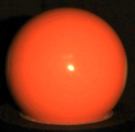
differential motions of the camera suffice to yield both depth (a) Image [1 of 5] (b) Depth map (c) Recovered surface
and a linear constraint on the gradient for a surface with
BRDF dependent on known light and half-angle directions. Figure 4. Reconstruction for a non-Lambertian ball with an unknown
BRDF, under unknown light source, using Proposition 8.
Proof. Prop. 8 already shows depth recovery from m ≥ 3
differential motions of the camera. Further, from the form of For evaluation with real data, images of the plastic sphere
π for half-angle BRDFs in (28) and using (39), we have in Fig. 4(a) are obtained against a textured background under
π1 a> n 2 unknown directional lighting. Note the clear non-Lambertian
= > = , (40) effects. The camera focal length is 55mm and the object is
π2 b n 3
approximately 80cm away. Five small motions (and several
where a and b are known entities dependent on light, defined large ones for stable pose optimization) are imparted to the
by (29). Finally, using (4) yields a linear PDE in depth: camera and estimated using bundle adjustment. The surface
l1 zx + l2 zy + l3 = 0, (41) depth obtained from Prop. 8 is shown in Fig. 4(b) and (c).
While we do not explore the direction in this paper, note
with l1 = 2 b1 − 3 a1 , l2 = 2 b2 − 3 a2 , l3 = 3 a3 − 2 b3 . that with known lighting, one may use the constraint (41) to
Thus, we obtain a linear constraint on the gradient. solve a joint depth and gradient optimization weighted by λ:
It is evident from the above result that materials for which min (z − 1 )2 + λ(l1 zx + l2 zy + l3 )2 . (42)
z
a relation between π1 and π2 may be derived independent
With standard differencing, the above is a highly sparse linear
of derivatives of the BRDF ρ, yield an additional constraint
system in z which may be solved efficiently.
on the surface gradient. The form of this constraint will
mirror the relationship between π1 and π2 , since their ratio is
6. Perspectives on Shape from Motion Theories
a measurable quantity from (40). In particular, it follows that
a linear constraint may also be derived for the more general We now provide a unified perspective on shape from mo-
case considered in Section 4.2.3: tion theories corresponding to light, object or camera motions.
Despite the apparent complexity of material behavior, differ-
Remark 2. Under perspective projection, three differential ential motion of light, object or camera allows shape recovery
motions of the camera suffice to yield both depth and a linear with unknown BRDF and often unknown lighting. More im-
constraint on the gradient for a BRDF dependent on known portantly, theoretical limits on shape from motion are also
light and an arbitrary direction in the source-view plane. derivable in these frameworks. Prior works have presented
theories for light [2] and object [4] motions. This paper has
5.3. Shape Recovery
studied camera motion to complete the differential analysis
From Prop. 8, depth is directly available in the perspective framework for shape recovery with unknown BRDFs.
case for unknown lighting and unknown BRDF. Fig. 3 illus- In Table 2, we summarize a few results from each theory.
trates this for synthetic data, where the object is imaged under In each case, the theories generalize well-known special cases
an unknown light source. The object has diameter 20cm and that assume Lambertian BRDF or brightness constancy. Only
is placed 1.5m away from the camera of focal length 10cm. orthographic projection for light motion (generalizing photo-
Three random motions, of approximately 2◦ rotation and 5mm metric stereo) and perspective projection for object or camera
translation are imparted to the camera. The recovered shape motion (generalizing optical flow and multiview stereo, re-
using the theory of Sec. 5.1 is shown in Fig. 3. No prior spectively) are shown. A complete table is provided in [1].
knowledge of the BRDF, lighting or depth are required. A few important traits are shared by these theories:Motion Light BRDF #Motions Surface Constraint Shape Recovery Theory
Light Known Lambertian 2 Lin. eqns. on gradient Gradient [19]
Light Unknown General, unknown 2 Linear PDE Level curves + k∇zk isocontours [2]
Object Brightness constancy 1 Lin. eqn. (optical flow) Depth [7, 9]
Object Colocated Uni-angle, Unknown 3 Lin. eqn. + Homog. lin. PDE Depth + Gradient [4]
Object Unknown Full, unknown 4 Lin. eqn. + Homog. lin. PDE Depth + Gradient [4]
Camera Brightness constancy 1 Lin. eqn. (stereo) Depth [15]
Camera Unknown General, unknown 3 Linear eqn. Depth Prop. 8
Camera Known Half angle, unknown 3 Lin. eqn. + Inhomog. lin. PDE Depth + Gradient Prop. 9
Table 2. A unified look at BRDF-invariant frameworks on shape recovery from motions of light source, object or camera. In each case, PDE
invariants specify precise topological limits on shape recovery. More general BRDFs or imaging setups require greater number of motions
to derive the reconstruction invariant. More restricted BRDFs require fewer motions or yield richer shape information. For comparison, the
traditional diffuse equivalents are also shown. Only the perspective cases are shown for object and camera motion (the full table is in [1]).
• They all rely on the linearity of chain rule differentiation to motion. We also anticipate robust estimation methods that
eliminate the BRDF from a system of equations. exploit our theory to extend traditional implementations of
• The invariant in each case can be characterized as a PDE optical flow and multiview stereo to handle general BRDFs.
amenable to solution through standard analysis tools. References
• The involved PDEs provide intrinsic limits on the topolog-
ical class upto which shape may be recovered from each [1] M. Chandraker. What camera motion reveals about shape with unknown
BRDF. Technical Report 2014-TR044r, NEC Labs America, 2014.
motion cue, regardless of reconstruction method. [2] M. Chandraker, J. Bai, and R. Ramamoorthi. A theory of differential
• More general imaging setups require greater number of photometric stereo for unknown isotropic BRDFs. In CVPR, pages
motions for shape recovery. For instance, colocated lighting 2505–2512, 2011.
requires less motions than general lighting, or perspective [3] M. Chandraker and R. Ramamoorthi. What an image reveals about
material reflectance. In ICCV, pages 1076–1083, 2011.
projections require more motions than orthographic. [4] M. Chandraker, D. Reddy, Y. Wang, and R. Ramamoorthi. What object
• Constraining the BRDF either reduces the minimum re- motion reveals about shape with unknown BRDF and lighting. In
quirement on number of motions (colocated or general CVPR, pages 2523–2530, 2013.
BRDFs for object motion), or provides richer shape infor- [5] J. Clark. Active photometric stereo. In CVPR, pages 29–34, 1992.
[6] H. W. Haussecker and D. J. Fleet. Computing optical flow with physical
mation (half-angle or general BRDFs for camera motion).
models of brightness variation. PAMI, 23(6):661–673, 2001.
The cases of object and camera motion are more closely [7] B. Horn and B. Schunck. Determining optical flow. Artificial Intelli-
gence, 17:185–203, 1981.
related, but with important differences due to additional ambi-
[8] F. John. Partial Differential Equations. App. Math. Sci. Springer, 1981.
guities entailed by camera motion. Qualitatively, this leads to [9] B. Lucas and T. Kanade. An iterative image registration technique with
a harder problem for the case of camera motion. The practical an application to stereo vision. In Image Understanding Workshop,
manifestation of this hardness is requiring a more restricted pages 121–130, 1981.
BRDF (although still unknown) to obtain the same shape in- [10] M. Minnaert. The reciprocity principle in lunar photometry. Astrophys-
ical Journal, 3:403–410, 1941.
formation. For instance, a half-angle BRDF yields depth and [11] H.-H. Nagel. On a constraint equation for the estimation of displace-
a gradient constraint with camera motion, while the same can ment rates in image sequences. PAMI, 11(1):13 –30, 1989.
be obtained with general BRDFs for object motion. Allowing [12] S. Negahdaripour. Revised definition of optical flow: Integration of
a general BRDF means only depth may be obtained for cam- radiometric and geometric cues for dynamic scene analysis. PAMI,
20(9):961–979, 1998.
era motion, while object motion yields an additional gradient [13] I. Sato, T. Okabe, Q. Yu, and Y. Sato. Shape reconstruction based on
constraint. Throughout this paper, we have highlighted such similarity in radiance changes under varying illumination. In ICCV,
distinctions and their impact on shape recovery. pages 1–8, 2007.
[14] S. Savarese, M. Chen, and P. Perona. Local shape from mirror reflec-
Future work Our theory focuses on shape recovery, but tions. IJCV, 64(1):31–67, 2005.
some BRDF information may also be recovered as a by- [15] S. Seitz, B. Curless, J. Diebel, D. Scharstein, and R. Szeliski. A com-
product. For instance, with perspective projection, Props. 8 parison and evaluation of multiview stereo reconstruction algorithms.
and 1 completely define π. That is, from (39), In CVPR, pages 519–526, 2006.
[16] J. T. Todd, J. F. Norman, J. J. Koenderink, and A. M. L. Kappers.
π = (1 + β1 )−1 (2 , 3 , 0)> . (43) Effects of texture, illumination and surface reflectance on stereoscopic
shape perception. Perception, 26(7):807–822, 1997.
Fig. 3 shows an example recovery of π. In turn, this places [17] A. Treuille, A. Hertzmann, and S. Seitz. Example-based stereo with
constraints on the derivative of BRDF. An avenue for future general BRDFs. In ECCV, pages 457–469, 2004.
work is to characterize the extents to which BRDF may be [18] A. Verri and T. Poggio. Motion field and optical flow: Qualitative
properties. PAMI, 11(5):490–498, 1989.
recovered using motions of the light source, object or camera. [19] P. Woodham. Photometric method for determining surface orientation
Further, while [2, 4] and this paper together provide limits from multiple images. Opt. Engg., 19(1):139–144, 1980.
on shape recovery from motions corresponding to each imag- [20] T. Zickler, P. Belhumeur, and D. Kriegman. Helmholtz stereopsis:
ing element, an interesting problem is to achieve similar limits Exploiting reciprocity for surface reconstruction. IJCV, 49(2/3):1215–
1227, 2002.
when lighting, object and camera all undergo simultaneousYou can also read


