ZomeFab: Cost-effective Hybrid Fabrication with Zometools - I-Chao Shen
←
→
Page content transcription
If your browser does not render page correctly, please read the page content below
Volume 0 (1981), Number 0 pp. 1–9 COMPUTER GRAPHICS forum

 ZomeFab: Cost-effective Hybrid Fabrication with Zometools

 I-Chao Shen Ming-Shiuan Chen Chun-Kai Hunag Bing-Yu Chen

 National Taiwan University

 Abstract
 In recent years, personalized fabrication has received considerable attention because of the widespread use of consumer-level
 three-dimensional (3D) printers. However, such 3D printers have drawbacks, such as long production time and limited output
 size, which hinder large-scale rapid-prototyping. In this paper, for the time- and cost-effective fabrication of large-scale objects,
 we propose a hybrid 3D fabrication method that combines 3D printing and the Zometool construction set, which is a compact,
 sturdy, and reusable structure for infill fabrication. The proposed method significantly reduces fabrication cost and time by
 printing only thin 3D outer shells. In addition, we design an optimization framework to generate both a Zometool structure
 and printed surface partitions by optimizing several criteria, including printability, material cost, and Zometool structure
 complexity. Moreover, we demonstrate the effectiveness of the proposed method by fabricating various large-scale 3D models.
 CCS Concepts
 • Computing methodologies → Shape modeling;

1. Introduction For a given 3D shape, we design an optimization process to syn-
 thesize the inner Zometool structure such that shape similarity and
The recent widespread adoption of consumer-level three-
 structural complexity are optimally traded off. Through simulated
dimensional (3D) printers spurred the growth of academic and in-
 annealing, we effectively explore the large structure space. Next,
dustrial fabrication applications. However, several drawbacks, in-
 using the optimized Zometool structure, we hollow out the shape
cluding long production time, limited output size, and high mate-
 to obtain the outer shell and partition such that several criteria, in-
rial costs, persist. Many approaches have been proposed to address
 cluding simplicity and printability, are satisfied. These criteria are
these shortcomings. To reduce production time and material costs,
 formulated as a single multiclass labeling problem and solved us-
modern 3D printers allow users to vary the fill rate. Furthermore,
 ing a graph-cut algorithm [BK04]. We then design a particular type
various internal patterns have been proposed [LSZ∗ 14] to reduce
 of connector and optimize its positions for assembling the inner
the amount of material used without sacrificing structural sound-
 Zometool structure and the outer shell.
ness. In addition, some methods [LBRM12, HLZCO14, VGB∗ 14]
have been proposed for large-scale fabrication, most of which are This paper makes two primary contributions:
based on the principle of partitioning large objects into smaller
components that are compatible with the printer’s output size. • We propose an optimization framework to synthesize the inner
 Zometool structure that replaces solid printed materials in large-
 Large-scale fabrication using extant methods remains expensive. scale fabrication.
To substantially reduce fabrication costs, we propose a hybrid fab- • We design and print a special connector and optimize its layout
rication method that integrates the use of 3D printing materials for effectively combining the inner Zometool structure and the
for the external shape with the use of a supporting structure for outer printed shell.
the internal volume. The inner structure must satisfy several cri-
teria; for example, the structure must be (1) easy to assemble, (2)
reusable, and (3) robust. These criteria ensure that the resulting fab- 2. Related Work
rication is simple to build while also being structurally reliable.
 2.1. Computational Fabrication
Zometool [Dav07] satisfies these requirements for coarse fabrica-
tion. Moreover, Zometool has other favorable characteristics, such In recent years, computational fabrication has attracted con-
as stability and lightness, which facilitate large-scale fabrication, siderable attention in the fields of computer graphics and hu-
and structural modularity, which facilitates fast fabrication. In this man-computer interaction [SBM16]. Numerous approaches have
work, we develop a computational method that integrates 3D print- been proposed for fabricating shapes that satisfy various objec-
ing with the Zometool structure to reduce the time and material tives (e.g., maintaining balance [PWLSH13, BWBSH14], reduc-
costs of large-scale fabrication. ing size [LBRM12], strengthening structural soundness [ZPZ13],

 c 2019 The Author(s)
Computer Graphics Forum c 2019 The Eurographics Association and John
Wiley & Sons Ltd. Published by John Wiley & Sons Ltd.
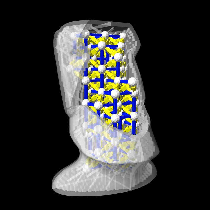
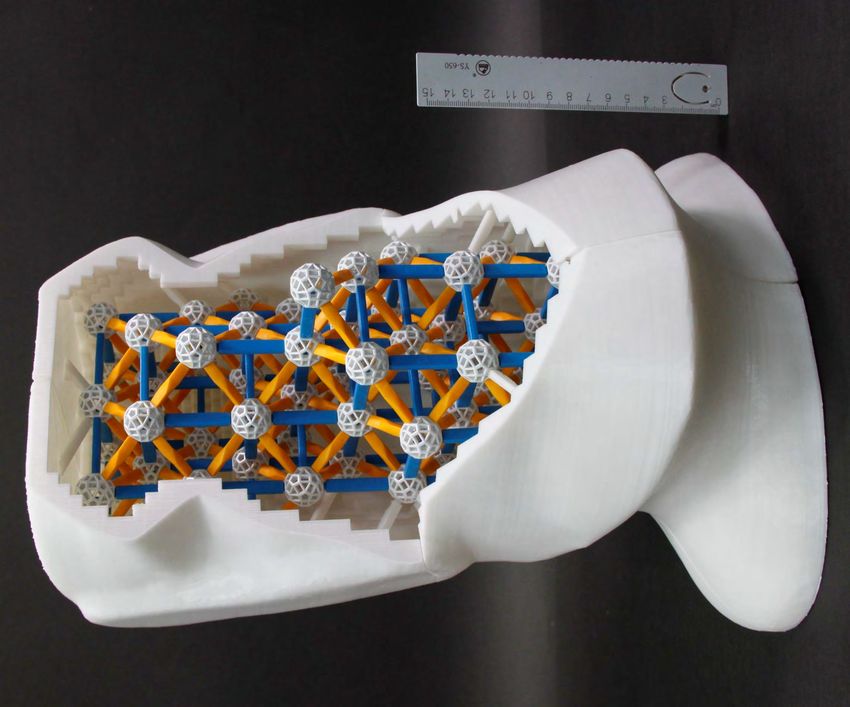
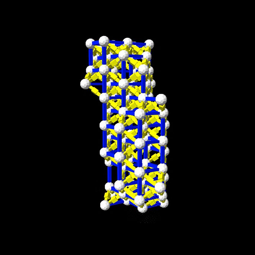
I-Chao Shen & Ming-Shiuan Chen & Chun-Kai Huang & Bing-Yu Chen / ZomeFab: Cost-effective Hybrid Fabrication with Zometools

and generating specific sounds [UPSW16]) while using vari- shape remains difficult because these systems do not provide sug-
ous materials and building blocks (e.g., Lego [LYH∗ 15], planar gestions to the users, such as what item to use next.
slices [CPMS14], and interlocking puzzles [SFCO12, ACP∗ 14]).
A detailed review of these approaches is available in [BCMP18]. To address these concerns, several studies have proposed auto-
 matic construction through the use of computational methods. Zim-
 Despite the development of assisting tools and algorithms, mer et al. approximated and realized freeform surfaces automat-
3D printers still have such drawbacks as long production time, ically by using Zometool. Zimmer and Kobbelt [ZK14] adopted a
excessive material use, and limited output size. To reduce the growth strategy that entails the use of incremental panels to approx-
consumption of print materials, Huang et al. [HZH∗ 16] and imate the desired surface without self-collisions.
Wu et al. [WPGM16] have designed devices and algorithms that
print shapes in wireframe form. In addition, several studies have de-
veloped different types of internal structures, such as the skin-frame
structure [WWY∗ 13] and the honeycomb-like structure [LSZ∗ 14]. 3. Overview
For the 3D printing of large structures, Luo et al. [LBRM12] de- Given a 3D shape M, the proposed method automatically gener-
veloped an iterative planar-cut method with the aim of fitting de- ates an inner Zometool structure and outer 3D-printed shells. This
composed parts within the 3D printing volume while considering method has the following features:
factors such as assemblability and aesthetics. Yao et al. [YCL∗ 15]
proposed a level-set framework for 3D shape partition and packing. 1. Large Objects. The proposed method is designed for fabricating
Compared with the aforementioned works, our method fabricates large-scale objects whose volume exceeds the printing volume of
a shape using both Zometool structures and 3D-printed pieces, most current consumer-level 3D printers.
thus reducing the fabrication time and cost given the reusability 2. Fabricability. Each segment of the outer shell can be printed
of Zometool structures. such that it fits inside the volume of consumer-level 3D printers.
 Several studies have focused on hybrid fabrication, for example, 3. Assemblability. The inner Zometool structure can be easily
CofiFab [SDW∗ 16], Universal Building Block [CLF∗ 18], and faB- assembled and connected to the outer printed shells by using
rickation [MIG∗ 14]. Our work primarily differs from [SDW∗ 16] specifically designed connectors.
and [CLF∗ 18] in the use of Zometool for fabricating the inter struc- 4. Cost-effectiveness. Our method maximizes the volume of the
ture. The advantages of Zometool are as follows: (i) Zometool is inner structure and minimizes the amount of printing materials
easy to obtain and manipulate compared with the customized laser- used.
cut shapes used in CofiFab; (ii) Zometool elements are reusable,
 Figure 1 illustrates our method. For a given input shape, we vox-
making them cheaper than the laser-cut shapes; and (iii) Zome-
 elize the inner volume of the input mesh to realize an initial Zome-
tool structures are relatively sparse, thus necessitating relatively
 tool structure. The objective is to grow the Zometool structure such
few building elements and enabling material savings. Different in-
 that it maximizes the inner volume, thus reducing the amount of
ter structures necessitate the use of different processes and algo-
 printing materials necessary. To this end, we design an optimiza-
rithms. For example, the applications of faBrickation differ from
 tion framework through simulated annealing and design several lo-
those of our method. In faBrickation, Lego bricks are used as the
 cal operations to explore the optimized Zometool structure space
main building blocks to realize shapes, whereas 3D-printed parts
 (see Section 4).
are used to fill the smaller components that are difficult to build
using Lego bricks. Next, to print the outer shell with the appropriate shape, we (i)
 partition the shape into pieces such that each piece fits inside the
 printing volume, (ii) place connectors at feasible locations so that
2.2. Zometool Design and Modeling the inner Zometool structure and the outer shell can be connected
Zometool is a mathematically precise plastic construction set used robustly, and (iii) maintain the salient regions intact. We formulate
for building a myriad of geometric structures [Dav07]; it can be this partition problem as a multi-label problem and solve it by using
used to visualize simple polygons as well as model complex struc- a graph-cut algorithm under the following considerations: each tri-
tures such as DNA molecules. Zometool dates back to the 1960s, angle must be connected to its closest Zomeball, but the number of
when it was first used as a simple construction system inspired by partitions must also be reduced without sacrificing the integrity of
Buckminster Fulleresque geodesic domes. Its application has since the salient regions. To further regularize the resulting partitions, we
evolved to satisfy the requirements of versatile modeling. Although apply a support vector machine (SVM) algorithm to determine the
Zometool can be used to construct complex structures, it is not an hyperplane between different labels. We then use this hyperplane
intuitive tool for new users, and its use can also be time consuming. as the cut plane to separate the mesh (see Section 5).
Various tools have been developed to help users design Zometool Before separating the mesh using the aforementioned cut plane,
structures, such as vZome∗ and ZomeCAD1 ; these systems provide we generate the inner surface by voxelizing the inner volume and
multiple methods to grow structures. However, building a complex combine it with the outer mesh as the solid mesh. Subsequently,
 we apply all the cut planes to the solid mesh and obtain the dis-
 tinct pieces. Finally, we design a special connector and connect the
∗ http://vzome.com printed pieces to the inner Zometool structure to form the designed
1 http://www.softpedia.com/get/Science-CAD/ZomeCAD.shtml large-scale object (Section 6).

 c 2019 The Author(s)
 Computer Graphics Forum c 2019 The Eurographics Association and John Wiley & Sons Ltd.
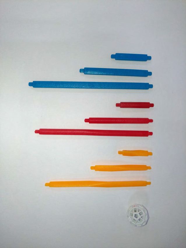
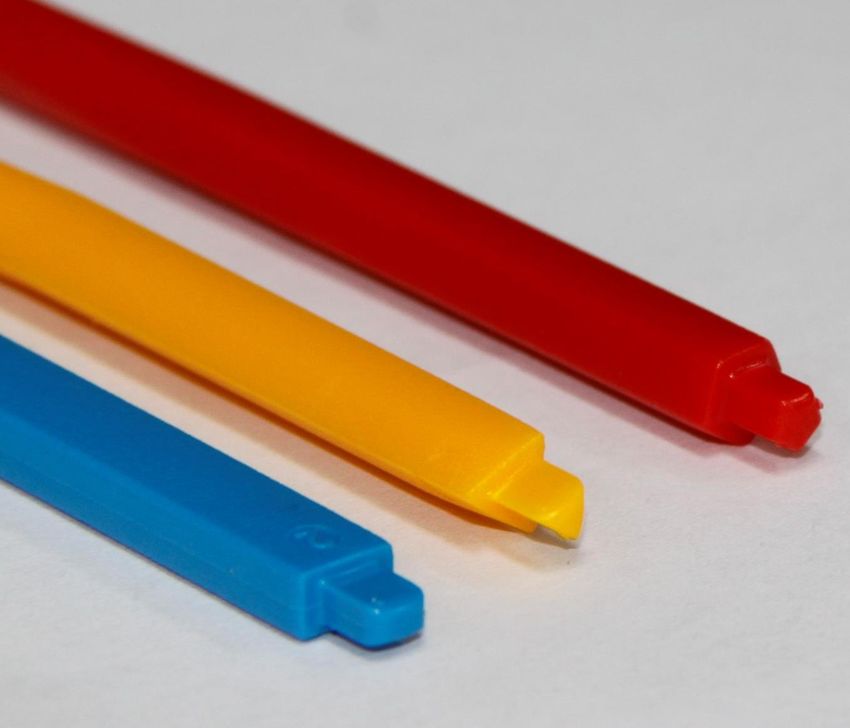
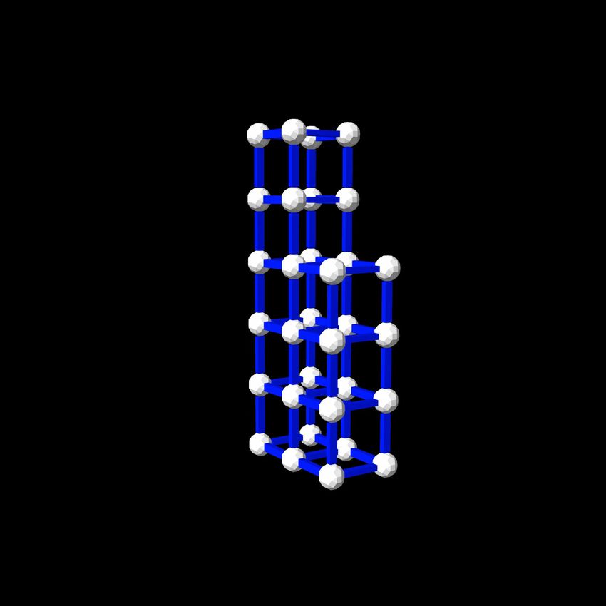
I-Chao Shen & Ming-Shiuan Chen & Chun-Kai Huang & Bing-Yu Chen / ZomeFab: Cost-effective Hybrid Fabrication with Zometools

Figure 1: For a given input shape, we first optimize the inner Zometool structure (Section 4). Guided by the Zometool structure, we then
partition the outer shell (Section 5) and generate connectors for assembling them (Section 6). The final fabricated result is obtained by
assembling both assembled Zometool structure and printed outer shell.

4. Zometool construction has the shortest assembly time. The major difference between our
 study and that of Zimmer et al. [ZLAK14] is that we choose b0
4.1. Introduction to Zometool
 (the length of the shortest blue rod) as the edge length of the cube;
Zometool is this is because the smaller is the cube, the higher is the fitting rate,
widely used as and the closer are the inner and outer surfaces (inset shows sample
an educational initialization).
toy that replicates
complex scien-
 4.3. Problem Formulation
tific structures,
such as chemical We measure the quality of the Zometool struc-
structures. The ture Z with energy E in terms of four quality
rods in the stan- measurements:
dard Zometool system have three types of struts: blue for rectangle,
red for pentagon, and yellow for triangle. Each strut comes in three E(Z) = wfid · Efid (Z) + wreg · Ereg (Z)
lengths, with length here defined as the distance from the center + wval · Eval (Z) + wsim · Esim (Z), (1)
of a ball on one end to the center of a ball on the other end (see
 We set w f id = 1.0, wreg = 100.0, wval = 1.0,
inset). We denote (b0 , b1 , b2 ) as the three lengths of the blue struts;
 wsim = 1.0 for all examples in this paper.
similarly, (r0 , r1 , r2 ) and (y0 , y1 , y2 ) represent the red and yellow
struts, respectively.
 √
 The ratio of the lengths follows the golden
 1+ 5 4.3.1. Shape fidelity
ratio, γ = 2 . For example, for the blue struts, b1 = b0 · γ and
b2 = b0 + b1 . Moreover, the relative length ratio of the yellow √
 and To better represent the input shape S, the out-
 3
blue struts and that of the red and blue struts differ: yi = 2 · bi and ermost nodes must stay close to the surface
 √ of S; that is, the distance from the outermost
ri = 2+γ
 2 · bi . Each Zomeball has 62 slots, namely 30 rectangular, nodes to the surface of S should be minimized.
12 pentagonal, and 20 triangular slots. Please refer to [Dav07] for
 Thus, the distance from Z to S is integrated
more details on the mathematical model of Zometool.
 over the outermost nodes:
 |Nout |
 1
4.2. Initialization Efid (Z) = 2 ∑ kpi − δ(pi )k2 · (1 + F(pi )), (2)
 |Nout | · dnorm i=1
Many complicated structures can be assembled using Zometool.
 where Nout is the set of outermost nodes and δ(pi ) is the point on
Nevertheless, the assembly complexity and time increase rapidly
 S nearest to the outermost nodes. The normalization factor dnorm
with the number of Zometool items (i.e., struts and balls) used. A
 is set as b0 to retain the energy within [0, 1]. We follow [ZLAK14]
simple and repeating unit structure is used to fabricate the initial
 and define the term F(p) as the forbidden zone that penalizes node
structure, following which the rest of the structure is built outward
 points lying too far away from the surface.
from the initial structure to achieve a good fit with the outer surface.
After experimenting with different basic structures (e.g., cubes, tri- Forbidden Zone F(p) is defined as a quadratically increasing
angular pyramids, square pyramids, and pentagonal pyramids), we function that is dependent on the distance between the node n and
select the cube as the unit building block for this study because it the nearest triangle centroid on surface M when the distance is

 c 2019 The Author(s)
Computer Graphics Forum c 2019 The Eurographics Association and John Wiley & Sons Ltd.
I-Chao Shen & Ming-Shiuan Chen & Chun-Kai Huang & Bing-Yu Chen / ZomeFab: Cost-effective Hybrid Fabrication with Zometools

 Fthick

 Fmax

 = 90° > 90°

 < 90°

 Figure 3: Regularity. We penalize configurations where the angle
 dmin dmax between the struts stray far from 90◦ .

Figure 2: Forbidden zone function F(p). Because Zometool ele-
ments that stay close to dmin are preferred, elements farther from
 reduces the optimization efficiency. Collided structures are con-
dmin are penalized.
 sidered to be invalid (because they can not be assembled) in our
 method (this is discussed subsequently herein). We set the target
 valence as 6 according to the initial cube structure, which mini-
within the range from dmin to dmax (as shown in Figure 2). We mizes the complexity and maximizes the utility of each Zomeball:
choose appropriate parameters by conducting tests on different 3D
 Nin
shapes. We thus identify the following set of parameters that pro- (Vi − 6)2
 Eval (Z) = ∑ , (4)
duce elements that do not extrude out the forbidden zone across i=1 6
all the tested shapes. F(p) is set as (i) a constant large penalty
(Fthick ) when the distance is less than dmin to prevent the Zome- where |Nin | denotes the number of internal nodes and Vi denotes
tool elements from growing between the outer surface and dmin , the valence of node ni ∈ Nin (Figure 4).
and (ii) Fmax when the distance exceeds dmax . By testing various
3D shapes, we found that the following set of parameters produce
results that do not extrude out of the forbidden zone for all the
tested shapes: dmin = 16.0 ( 31 length of b0 ) , dmax = 47.3 (length of
b0 ), Fmax = 70.0, and Fthick = 90.0; these values are thus used all
examples in this paper.

4.3.2. Regularity (a) (c)

On observing the assembling process of several complicated Zome-
tool structures, we discover two major states that slow down the
process: (i) the struts on a Zomeball are too close to each other
(i.e., the angles between the struts are too small), and (ii) the slots (b) (d)
used to connect the struts are spread out irregularly on the Zome-
ball. To address these concerns, we regularize the angles between
struts to be exactly 90◦ and penalize any angle that is too small or Figure 4: Valence. We encourage the valence of each Zometool
too large (Figure 3) node to be 6 (as in configuration (a) and (b)). We penalize the va-
 lence that is not 6 (configuration (c) and (d)).
 S
 1 π
 Ereg (Z) = ∑ |Ni | ∑ (min(θi j ) − ), (3) 4.3.4. Shape simplicity
 i=1 s j ∈Ni 2
 To reduce the complexity of the Zometool structure, we limit
where S represents the number of struts and Ni represents the struts
 the number of Zometool elements. However, oversimplifica-
adjacent to strut i. The resulting Zometool structure has a rela-
 tion negates the effects of the shape fidelity energy discussed in
tively high number of repeated Zomeball patterns (the struts on
 Section 4.3.1; that is, the desired shape cannot be adequately replicated.
each Zomeball are placed at similar slots), and this considerably
 For the optimal trade-off of shape fidelity and simplicity, we deter-
reduces the assembling time.
 mine the target number of Zometool elements before optimization.
 To this end, we run a random Zometool assembling process ten
4.3.3. Valence
 times within the volume of the input shape. For each run, we record
For ease of assembly, we regularize the optimized Zometool struc- the number of Zometool elements required to reach a predefined
ture such that it has good valence for simple structures (see Fig- shape similarity threshold between the Zometool structure and
ure 4). The primary reason for regularizing valence number is the target shape M. We set the 90% of the average number of
that an undesired Zomeball valence number (Figure 4 (c) and (d)) Zometool elements as the final target item number (τ). For most
increases the possibility of element collision, which considerably cases, this target number serves as the upper bound of the number

 c 2019 The Author(s)
 Computer Graphics Forum c 2019 The Eurographics Association and John Wiley & Sons Ltd.
I-Chao Shen & Ming-Shiuan Chen & Chun-Kai Huang & Bing-Yu Chen / ZomeFab: Cost-effective Hybrid Fabrication with Zometools

of elements, and the simulated annealing optimization process is
always terminated before this target number is reached. Let |N|
represent the total number of nodes, and |S| represent the total
number of struts. Simplicity is measured as the difference between (a) (b)
the actual and target item numbers:
 1
 Esim (Z) = (|N| + |S| − τ)2 . (5)
 τ
 (c) (d)
4.4. Exploration Mechanism
Determining the Zometool structure that minimizes the energy
E(Z) (Eq. 1) is a nontrivial optimization problem because E(Z) is
nonconvex and contains global terms. Because an exhaustive search (e) (f)
is impractical, we adopt a more scalable strategy based on the sim-
ulated annealing algorithm [SFS02]. In a nutshell, this algorithm Figure 5: We use six local operations during structure perturba-
executes a random exploration of the solution space by iteratively tion. (a) InsNode, (b) DelNode, (c) InsStrut, (d) DelStrut, (e) Ins-
perturbing the current solution with a certain probability depending Bridge, and (f) DelBridge. Each operation is performed from the
on the energy variation between the two solutions and a relaxation left configuration to the right configuration.
parameter T . We describe our local perturbation operators and re-
laxation scheme as follows. Algorithm 1 details our optimization
algorithm. to Zomeball, (2) strut to Zomeball, and (3) strut to strut distances;
 if the distance is less than a certain threshold, the update is rejected.
Algorithm 1 Exploration mechanism
 1: Input: Initialized Zometools Z̄, 4.4.1. Cooling schedule
 2: relaxation parameter T = Tinit
 3: Output: Optimized Zometoos Z The relaxation parameter T , referred to as temperature, controls
 4: procedure E XPLORATION(Z) both the speed and quality of the exploration. Starting from an
 5: repeat initial temperature Tinit , we decrease the temperature, approaching
 6: generate Z0 from Z with a random local operation. zero as the iteration tends to infinity. This process is referred to as
 7: draw a random value p ∈ [0, 1] cooling, and various cooling schedules are available. Although the
 E(Z)−E(Z0 ) logarithmic cooling schedule [SFS02] guarantees global minimum
 8: if p < exp( T ) and CollisionFree(Z) then
 convergence, we implement a geometric cooling schedule [HJJ03].
 9: update Z0 ← Z
 In our experiment, we set the initial temperature Tinit = 1 and apply
10: end if
 the decrease rate C = 0.99 after every 100 iterations.
11: Update T ← C × T .Update temperature.
12: until T < Tend
13: end procedure 5. Object Partition
 Most consumer-level 3D printers have limited printing volumes.
Local Perturbation Operation During the exploration, we pro-
 To print large-scale objects, the objects must be decomposed into
posed six local perturbation operations (Figure 5) to construct the
 smaller partitions. Conventional surface partition methods only ac-
Zometool structure by minimizing Eq. 1.
 count for surface features; however, we must also consider the re-
 • InsNode This operator inserts a new node and two struts to split lationship between the outer surface partitions and the inner opti-
 the original strut. mized Zometool structure. Specifically, in this work, we place con-
 • DelNode This operator deletes a node and two struts. nectors between the outer and inner structures in order to connect
 • InsStrut This operator inserts a single strut to connect two them (see Section 6). We can simply compute the distance between
 nodes that are not directly linked. each triangle t and all nodes in Z and assign t to the nearest node
 • DelStrut This operator deletes a strut between two nodes that as its label. However, inconsistencies may arise among adjacent
 are directly linked. triangles, engendering unsatisfactory visual effects and assembly
 • InsBridge This operator inserts a new strut to merge two nodes complexities because numerous small partitions might exist (Fig-
 that are not directly linked (two nodes with connected path ure 6(a)).
 length more than two).
 To address this concern, we formulate the problem as a multi-
 • DelBridge This operator deletes a strut between two nodes with
 label graph-cut minimization problem. As each triangle t can po-
 connected path length more than two.
 tentially correspond to different Zometool nodes, it gets assigned
 Operation validity The chosen operation at each iteration up- data costs for different corresponding nodes. Given n elements,
dates the structure from the previous iteration. However, some up- k labels, and n · k costs, finding the minimum assignment is a
dates might introduce invalid structures, such as structures with typical NP-hard combinatorial problem, which we solve using
item collision. We detect collision by checking the (1) Zomeball Boykov [BK04].

 c 2019 The Author(s)
Computer Graphics Forum c 2019 The Eurographics Association and John Wiley & Sons Ltd.
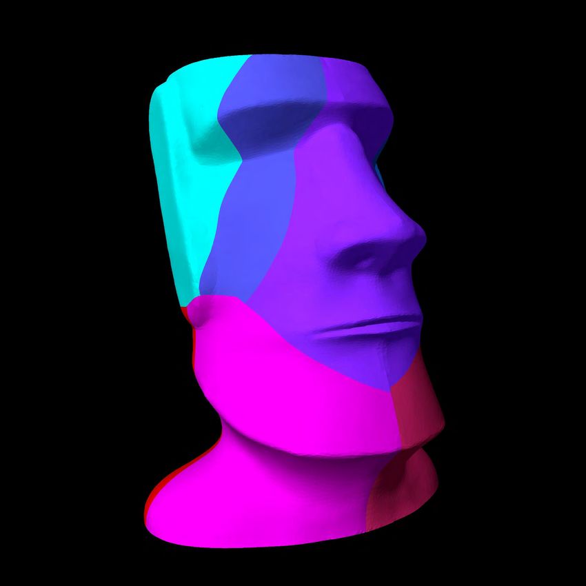
I-Chao Shen & Ming-Shiuan Chen & Chun-Kai Huang & Bing-Yu Chen / ZomeFab: Cost-effective Hybrid Fabrication with Zometools

 After partitioning the structure, we further regularize the bound-
aries between the partitions by performing multi-class clas-
sification; this process of seeking smooth boundaries ensures
easy assembly. This problem has been previously addressed by
Wang et al. [WZK16] and Alderighi et al. [AMG∗ 18]. We follow
[WZK16] and use an SVM [CV95] classifier to determine our
cut plane. We describe the formulation and implementation of a
Markov random field (MRF) problem and how to find the cut planes
in the following paragraph.

 (a) (b) (c) (d)

Figure 6: (a) Result of nearest node classification (b) result of
graph cut, (c) cut-plane generated using an SVM classifier, and (d) Figure 7: In the left-most column, we show optimized partitions
cutting result. without introducing the user-guided saliency term. We can observe
 that the partition cut through some salient features on the mesh. To
 address this problem, the user annotates the region that they wish
 to preserve (red region in the middle column). We then incorporate
5.1. Surface Partition an additional term in the original smoothness term to prevent the
 annotated regions from separating into multiple parts (right-most
5.1.1. Optimization energy column).
We compute the assignment function f that assign labels to each
triangle t, where t ∈ T , such that the labeling f minimize the fol-
lowing energy E( f ): neighboring elements.
 (
 E( f ) = wdata ∑ D(t, ft ) + wsmoothness ∑ ψt,s (t, s, ft , fs ), (6) 0, if lt = ls ,
 t∈T t,s∈N ψt,s (t, s, lt , ls ) =
 − log(θt,s /π)ϕt,s + wsaliency ∗ Esaliency (t), otherwise
where ft and fs are labels assigned to triangle t and s, and N is the (8)
set of all pairs of triangles sharing edges. We set wdata = 1.0 for
all the shapes shown in this paper, and we use wsmoothness to control where we set wsaliency = 5.0, and θ p,q and ϕ p,q are the dihedral
the size of the partitions, which is crucial for limiting the size of the angle and the centroid distance between triangles p and q, respec-
partitions such that they fit within the 3D printing volume. Specif- tively. With the smoothness term, two adjacent triangles are likely
ically, we initialize wsmoothness as 10 and examine whether we can to have consistent labels. Each object has many salient regions that
fit all the partitions within the 3D printing volume. If not, we multi- the the partition seam must not go through (e.g., the eyes and nose
ply wsmoothness by 0.1 and repeat this process until all the partitions on the face in Figure 7). To preserve the integrity of the salient re-
fit into the desired volume. We optimize this function by using the gions, we ask users to draw the region that they wish to preserve,
multilabel graph-cut algorithm proposed by Boykov [BK04]. In our and we formulate this requirement as part of the smoothness cost to
setting, the entire outer nodes of Z form the complete possible label prevent the partition seams from cutting through the salient region
set L. This E( f ) comprises two terms: data cost and smoothness. (see last column of Figure 7).

 Data cost. We measure how well a triangle t covers an outermost (
node n ∈ Nout as data cost. This cost is simply defined as the dis- 1, triangle is marked as salient region,
tance between the centroid of the triangle t and the outermost node Esaliency (t) = (9)
 0, otherwise
n ∈ Nout .

 D(t, ft ) = log(d(t, n)). (7) 5.1.2. Optimized partitions

Noted that the set of possible ft is the set of node id of outermost We solve the labeling problem in Eq. 6 by using a graph-cut algo-
nodes. rithm and obtain 11 labels on the Maoi head object (Figure 6(b)).
 Compared with the method that directly assigned the triangle to the
 Smoothness cost. This term measures the spatial consistency of closest outermost node, our approach yields much smaller partition

 c 2019 The Author(s)
 Computer Graphics Forum c 2019 The Eurographics Association and John Wiley & Sons Ltd.
I-Chao Shen & Ming-Shiuan Chen & Chun-Kai Huang & Bing-Yu Chen / ZomeFab: Cost-effective Hybrid Fabrication with Zometools

numbers (11 vs. 60 (Figure 6(a)), and each partition is of relatively usually filled with the support materials, and it is difficult to remove
better shape and size. all of them. Hence, we choose to grown tenons on the inner surface
 with following method.
5.2. Object Cut Grow tenons on the surface. Given it’s easier cleanup and more
 robust structure, we use this design to connect the inner Zometool
To cut the physical object into pieces, we must find the cut
 structure and outer shell (see Figure 8 (b)). We restricted the grown
planes that separate the space occupied by the object. How-
 tenons have to be perpendicular to the inner surface in order to
ever, the boundaries between the optimized partitions are not
 achieve better structural robustness. And we decide how many
regular enough to be directly used as the separating plane
 tenons on each outer shell with the following process: We shoot
(see Figure 6(b) and the inset). It is very difficult to find the
 rays from each admissible slot on a single Zomeball in the opti-
plane in 3D space because of the varied plane normal vectors.
 mized Zometool structure, and record whether it intersects with the
Moreover, the zig-zag partition boundaries intro-
 tested shell. Since the tenons are only generated perpendicular to
duce additional complexities in the 3D printing
 the inner voxel surface, it’s direction is basically axis-aligned. This
process; thus, we find a clean separating plane by
 means that for each Zomeball, only 6 slots are admissible for each
following [WZK16] and analogizing our problem
 tenon. We repeated this examination on all of 6 slots on each of
as a multiclass classification problem, which is
 the Zomeball covered by this shell, and we find the directions that
then solved using SVM. We use each triangle as
 are perpendicular to the inner surface and grow tenons along those
a data sample, with it’s location as the feature vec-
 directions.
tor and the optimized label as it’s class. Briefly, the
SVM algorithm finds the best hyperplane, which
is the one that represents the largest separation,
or margin, between the two adjacent classes. Be-
cause we found that the hyperplanes obtained using SVM suffice
to cut the planes, we did not proceed with the subsequent step sug-
gested described in [WZK16] (Figure 6(c)).

 (a) (b)
6. Fabrication
The object to be printed should be a solid mesh. In our method, we Figure 8: Connector designs: (a) dig holes and (b) grow tenons on
use the Zometool structure to fill in most of the inner volume while inner surface. The materials in the dug holes can not be removed
retaining a predefined thickness of the outer shell. The minimum entirely in (a), so the struts can not be inserted well.
thickness is dependent on the requirements of the 3D printer used.
To print each solid piece, we must obtain the inner surface and use
the original surface as the outer surface. The inner surface can be 7. Result
generated in many approaches, such as by shrinking the mesh along
the vertex normals. However, these approaches often generate sur- 7.1. Experiment environment
faces with flipped triangles that stick out of the outer surface. To We implement ZomeFab in C++ and Python on desktop PC with
prevent this problem, we instead voxelize the original object and 3.4GHz CPU and 16GB memory. The computation time of Zome-
remove the voxels whose center falls within the minimum thick- tool structure usually takes around 0.5 - 2.5 hrs due to the con-
ness from surface. We then use the outermost surface of the re- vergence of the simulated annealing. The multi-label graph cut al-
maining voxels as our inner surface solid piece. As discussed in gorithm takes around 2 mins for all shapes shown in the paper.
Section 4.3.1, we penalize the Zometool elements that grow within The outer surfaces are printed by Ultimaker 3, a low-cost FDM 3D
the range of dmin (which is our default thickness). For all the shapes printer with 0.2m x 0.2m x 0.2m printing volume and PLA mate-
shown in this paper, no Zometool elements poked out beyond the rial.
surface.

 7.2. Evaluation
6.1. Generate connector
 We evaluate the material cost and fabrication time between “Zome-
With the inner surface, we need to place connectors on it to connect fab" and solid-printed object (denoted as “baseline" method). We
between inter Zometool structure and outer shells. Two potential use CURA2 , a slicer software for 3D printing, to simulate the fabri-
designs for building these connectors are: cation time and used materials for solid-printed object. Meanwhile,
1. Dig holes on the surface and use the Zometool struts to connect we subdivide the shape using a octree, and stop the subdivision
 both inter and outer structures (Figure 8 (a)). once each sub-shape fit into the printing volume. To evaluate our
2. Grow Zometool tenons on the inner surface (Figure 8 (b)). method, we report two different infill methods called “hollow" and
 “solid". Shapes printed under “hollow" use only 20% infill rate,
We tried both designs, and as we experimented, we observed that
the generated support structures from the 3D printers hugely reduce
the quality of the digged holes. The reason is the printed holes are 2 https://ultimaker.com/en/products/ultimaker-cura-software

 c 2019 The Author(s)
Computer Graphics Forum c 2019 The Eurographics Association and John Wiley & Sons Ltd.
I-Chao Shen & Ming-Shiuan Chen & Chun-Kai Huang & Bing-Yu Chen / ZomeFab: Cost-effective Hybrid Fabrication with Zometools

where “solid" use 100% infill rate. Note that we only use 20% in- 9. Acknowledgements
fill rate to fabricate the results shown in this paper, and the “solid"
 We would like to thank Sheng-Jie Luo, Hsin-I Chen and anony-
results are simulated using CURA.
 mous reviewers for insightful suggestions and discussions. During
 Material cost. As shown in Table 1, our method greatly saves this work, I-Chao Shen was supported by the MediaTek Fellowship.
materials from 24% to 64% under “hollow” setting, and from 68% This research was supported in part by the Ministry of Science and
to 85% under “solid” setting. As expected that our method brings Technology of Taiwan (MOST105-2218-E-002-011) and National
more benefits when infill rate grows. The material cost are listed Taiwan University.
as follow: 0.56 USD/meter, Zometool strut: 0.19 USD/strut and
Zomeball: 0.29 USD/ball for our experiments.
 References
 Fabrication time. We report printing time evaluation under sin-
gle 3D printer scenario and assembling time of zometool structure [ACP∗ 14] A LEMANNO G., C IGNONI P., P IETRONI N., P ONCHIO F.,
in Table 1. The statistics show that the overall fabrication time, S COPIGNO R.: Interlocking pieces for printing tangible cultural heritage
 replicas. In Proceedings of the Eurographics Workshop on Graphics and
i.e. printing time of outer pieces plus the assembly time of Zome-
 Cultural Heritage (2014), Eurographics Association, pp. 145–154. 2
tool structure, is on average 30% shorter than the baseline method
under “hollow” setting, and 74% under “solid” setting. [AMG∗ 18] A LDERIGHI T., M ALOMO L., G IORGI D., P IETRONI N.,
 B ICKEL B., C IGNONI P.: Metamolds: Computational design of
 silicone molds. ACM Trans. Graph. 37, 4 (July 2018), 136:1–
7.3. Zometool Use 136:13. URL: http://doi.acm.org/10.1145/3197517.
 3201381, doi:10.1145/3197517.3201381. 6
Table 2 shows the quantity of Zometool struts and balls used in [BCMP18] B ICKEL B., C IGNONI P., M ALOMO L., P IETRONI N.:
each result. In Section 4, we use smallest blue struts to make the State of the art on stylized fabrication. Computer Graphics Forum
zomecube as the unit structure in order to make the best-fit initial 37 (2018). URL: http://vcg.isti.cnr.it/Publications/
structure. The bigger the object is, more smallest blue struts (b0 ) 2018/BCMP18. 2
will be used. We also observed that, blue struts and yellow struts [BK04] B OYKOV Y., KOLMOGOROV V.: An experimental comparison
are more likely to be used interchangeably since we encourage reg- of min-cut/max-flow algorithms for energy minimization in vision. IEEE
ularity during simulated annealing optimization. Meanwhile, the Trans. Pattern Anal. Mach. Intell. 26, 9 (2004), 1124–1137. 1, 5, 6
rule of Zometool indicates that the longest strut only can be re- [BWBSH14] BÄCHER M., W HITING E., B ICKEL B., S ORKINE -
placed by one shortest and middle strut in the same color. So it H ORNUNG O.: Spin-It: Optimizing moment of inertia for spinnable
 objects. ACM Trans. Graph. (Proc. SIGGRAPH 2014) 33, 4 (2014),
seldom introduces red struts into the structure, which resulted in 96:1–96:10. 1
the used number of struts imbalance shown in Table 2. To ease the
assembling process of Zometool structure, we wrote a simple inter- [CLF∗ 18] C HEN X., L I H., F U C.-W., Z HANG H., C OHEN -O R
 D., C HEN B.: 3d fabrication with universal building blocks and
face that can highlight the connected struts for each ball. This can pyramidal shells. ACM Trans. Graph. 37, 6 (Dec. 2018), 189:1–
greatly improve the efficiency of the assembling process. 189:15. URL: http://doi.acm.org/10.1145/3272127.
 3275033, doi:10.1145/3272127.3275033. 2

8. Conclusion [CPMS14] C IGNONI P., P IETRONI N., M ALOMO L., S COPIGNO R.:
 Field-aligned mesh joinery. ACM Trans. Graph. 33, 1 (2014), 11:1–
In this paper, we propose ZomeFab, a hybrid fabrication method 11:12. 2
that combines Zometool and 3D printing to fabricate a large-scale [CV95] C ORTES C., VAPNIK V.: Support-vector networks. Mach. Learn.
3D object. We aimed at decomposing an input 3D object into a in- 20, 3 (1995), 273–297. 6
ner structure and pieces of outer surface. By replacing the huge in- [Dav07] DAVIS T.: The mathematics of zome, 2007. 1, 2, 3
ner space with Zometool from 3D printed materials, we can greatly
 [HJJ03] H ENDERSON D., JACOBSON S. H., J OHNSON A. W.: The The-
reduce the cost of 3D printing. And we retain the fine geometric de- ory and Practice of Simulated Annealing. Springer US, 2003. 5
tail by printing the outer shell with 3D printer. With the reusability
 [HLZCO14] H U R., L I H., Z HANG H., C OHEN -O R D.: Approximate
of Zometool, the long-term cost of fabrication is greatly decreased.
 pyramidal shape decomposition. ACM Trans. Graph. 33, 6 (2014),
We have demonstrated that our method is able to fabricate large- 213:1–213:12. 1
scale object by physically replicating 5 objects.
 [HZH∗ 16] H UANG Y., Z HANG J., H U X., S ONG G., L IU Z., Y U L.,
 Limitations and Future Work. There are many remaining chal- L IU L.: Framefab: Robotic fabrication of frame shapes. ACM Trans.
lenges and opportunities for future research on large-scale fabrica- Graph. 35, 6 (2016), 224:1–224:11. 2
tion. While our initial unit structure is simple and easy-to-assemble, [LBRM12] L UO L., BARAN I., RUSINKIEWICZ S., M ATUSIK W.:
it’s size (4.7cm x 4.7cm x 4.7cm) prevents us to fabricate 3D ob- Chopper: Partitioning models into 3D-printable parts. ACM Trans.
 Graph. (Proc. SIGGRAPH Asia 2012) 31, 6 (2012). 1, 2
ject with thin structure. Meanwhile, since Zometool is designed un-
der formal and strict mathematical formulation, the connection be- [LSZ∗ 14] L U L., S HARF A., Z HAO H., W EI Y., FAN Q., C HEN X.,
tween two separated Zometool sub-structure might not exist within S AVOYE Y., T U C., C OHEN -O R D., C HEN B.: Build-to-last: Strength
 to weight 3D printed objects. ACM Trans. Graph. 33, 4 (2014), 97:1–
the 3D object inner space. As a result, our method can not fabricate 97:10. 1, 2
3D object with two or more parts connected by thin structure that
 [LYH∗ 15] L UO S.-J., Y UE Y., H UANG C.-K., C HUNG Y.-H., I MAI S.,
our initial unit structure can not fit in. In the future, we would love N ISHITA T., C HEN B.-Y.: Legolization: Optimizing LEGO designs.
to investigate how to shrink the size of the initial unit structure, in ACM Trans. Graph. (Proc. SIGGRAPH Asia 2015) 34, 6 (2015), 222:1–
order to enable more complicated large-scale 3D object fabrication. 222:12. 2

 c 2019 The Author(s)
 Computer Graphics Forum c 2019 The Eurographics Association and John Wiley & Sons Ltd.
I-Chao Shen & Ming-Shiuan Chen & Chun-Kai Huang & Bing-Yu Chen / ZomeFab: Cost-effective Hybrid Fabrication with Zometools

 Single 3D Printer Fabrication Time (hours) Material Cost (USD) Efficiency (Saved)
 Mesh Infill Method Fabrication Method
 3D printing Zometool (assemble time) Overall (sum) 3D printing Zometool Overall (max) Time Material
 Zomefab 293.97 2.5 296.47 82.56 70.57 153.13
 Hollow 31.70% 13.83%
 Baseline 434.08 434.08 177.71 177.71
 Moai
 Zomefab 523.20 2.5 525.70 170.9 70.57 241.47
 Solid 77.75% 65.11%
 Baseline 2362.28 2362.28 692.07 692.07
 Zomefab 355.05 3.0 358.05 100.38 77.55 177.93
 Hollow 22.04% 21.74%
 Baseline 459.28 459.28 227.37 227.37
 Squirrel
 Zomefab 643.65 3.0 646.65 213.96 77.55 291.51
 Solid 76.57% 66.17%
 Baseline 2759.72 2759.72 861.66 861.66
 Zomefab 356.60 4.0 360.60 101.38 76.34 177.72
 Hollow 37.88% 21.91%
 Baseline 580.48 580.48 227.59 227.59
 Doraemon
 Zomefab 643.65 4.0 647.65 227.78 76.34 304.12
 Solid 57.71% 64.25%
 Baseline 1531.42 1531.42 850.79 850.79
 Zomefab 273.68 3.0 276.68 72.32 61.48 133.80
 Hollow 27.76% 36.38%
 Baseline 383.02 383.02 178.88 178.88
 Totoro
 Zomefab 468.82 3.0 471.82 148.26 61.48 209.74
 Solid 77.68% 68.09%
 Baseline 2113.42 2113.42 657.31 657.31
 Zomefab 282.30 2.0 284.30 73.99 57.76 131.75
 Hollow 34.98% 34.12%
 Baseline 437.25 437.25 199.97 199.97
 Iron Man
 Zomefab 477.03 2.0 479.03 149.67 57.76 207.43
 Solid 80.65% 72.93%
 Baseline 2475.22 2475.22 766.24 766.24

 Table 1: ZomeFab’s performance on saving time & material time as compared to a baseline method.

 Zometool
 Mesh Blue Red Yellow
 Total struts Total balls
 S M L S M L S M L
 Moai 112 0 0 0 0 0 140 0 0 252 73
 Squirrel 144 22 0 8 4 0 119 3 1 301 85
 Doraemon 143 26 1 2 5 1 89 1 1 569 87
 Totoro 95 0 0 0 0 0 137 0 0 232 60
 Iron Man 93 0 0 0 0 0 124 0 0 217 57
 Owl 115 0 0 0 0 0 159 0 0 274 70
 Pig 61 12 0 10 8 0 53 6 0 150 47
 Slime 132 0 0 0 0 0 182 0 0 314 80
 Lion 78 0 0 0 0 0 101 0 0 179 50
 Bunny 215 0 0 0 0 0 266 0 0 481 126

 Table 2: Zometool element usage.

[MIG∗ 14] M UELLER S., I M S., G UREVICH S., T EIBRICH A., P FIS - [VGB∗ 14] VANEK J., G ALICIA J. A. G., B ENES B., M ECH R., C ARR
 TERER L., G UIMBRETIÈRE F., BAUDISCH P.: Wireprint: 3D printed N. A., S TAVA O., M ILLER G. S. P.: PackMerger: A 3D print volume
 previews for fast prototyping. In Proc. ACM UIST ’14 (2014), pp. 273– optimizer. Comput. Graph. Forum 33, 6 (2014), 322–332. 1
 280. 2 [WPGM16] W U R., P ENG H., G UIMBRETIÈRE F., M ARSCHNER S.:
[PWLSH13] P RÉVOST R., W HITING E., L EFEBVRE S., S ORKINE - Printing arbitrary meshes with a 5DOF wireframe printer. ACM Trans.
 H ORNUNG O.: Make It Stand: Balancing shapes for 3D fabrication. Graph. 35, 4 (2016), 101:1–101:9. 2
 ACM Trans. Graph. (Proc. SIGGRAPH 2013) 32, 4 (2013), 81:1–81:10.
 [WWY∗ 13] WANG W., WANG T. Y., YANG Z., L IU L., T ONG X.,
 1
 T ONG W., D ENG J., C HEN F., L IU X.: Cost-effective printing of 3D
[SBM16] S HAMIR A., B ICKEL B., M ATUSIK W.: Computational tools objects with skin-frame structures. ACM Trans. Graph. 32, 6 (2013),
 for 3D printing. In ACM SIGGRAPH 2016 Courses (2016), pp. 9:1–9:34. 177:1–177:10. 2
 1
 [WZK16] WANG W. M., Z ANNI C., KOBBELT L.: Improved surface
[SDW∗ 16] S ONG P., D ENG B., WANG Z., D ONG Z., L I W., F U C.-W., quality in 3D printing by optimizing the printing direction. Comput.
 L IU L.: CofiFab: Coarse-to-fine fabrication of large 3D objects. ACM Graph. Forum (Proc. EG 2016) 35, 2 (2016), 59–70. 6, 7
 Trans. Graph. (Proc. SIGGRAPH 2016) 35, 4 (2016). 2
 [YCL∗ 15] YAO M., C HEN Z., L UO L., WANG R., WANG H.: Level-set-
[SFCO12] S ONG P., F U C.-W., C OHEN -O R D.: Recursive interlocking based partitioning and packing optimization of a printable model. ACM
 puzzles. ACM Trans. Graph. (SIGGRAPH Asia 2012) (2012), 128:1– Trans. Graph. 34, 6 (2015), 214:1–214:11. 2
 128:10. 2
 [ZK14] Z IMMER H., KOBBELT L.: Zometool rationalization of freeform
[SFS02] S ALAMON P., F ROST R., S IBANI P.: Facts, conjectures, and im- surfaces. IEEE Trans. Vis. Comput. Graph. 20, 10 (2014), 1461–1473. 2
 provements for simulated annealing. Society for Industrial and Applied
 Mathematics, 2002. 5 [ZLAK14] Z IMMER H., L AFARGE F., A LLIEZ P., KOBBELT L.: Zome-
 tool shape approximation. Graph. Models 76, 5 (2014), 390–401. 3
[UPSW16] U METANI N., PANOTOPOULOU A., S CHMIDT R., W HITING
 E.: Printone: Interactive resonance simulation for free-form print-wind [ZPZ13] Z HOU Q., PANETTA J., Z ORIN D.: Worst-case structural anal-
 instrument design. ACM Trans. Graph. 35, 6 (2016), 184:1–184:14. 2 ysis. ACM Trans. Graph. 32, 4 (2013), 137:1–137:12. 1

 c 2019 The Author(s)
Computer Graphics Forum c 2019 The Eurographics Association and John Wiley & Sons Ltd.
I-Chao Shen & Ming-Shiuan Chen & Chun-Kai Huang & Bing-Yu Chen / ZomeFab: Cost-effective Hybrid Fabrication with Zometools

 15 cm

 15 cm

 15 cm

 15 cm

 15 cm

Table 3: We fabricated five shapes using our method, and show the printed pieces (1st column), inner Zometool structure (2nd column), and
assembled final results (3rd and 4th column). Noted that the scale of 2nd, 3rd, and 4th columns are the same.

 c 2019 The Author(s)
 Computer Graphics Forum c 2019 The Eurographics Association and John Wiley & Sons Ltd.
You can also read