3D printed Ti6Al4V bone scaffolds with different pore structure effects on bone ingrowth
←
→
Page content transcription
If your browser does not render page correctly, please read the page content below
Deng et al. Journal of Biological Engineering          (2021) 15:4
https://doi.org/10.1186/s13036-021-00255-8

 RESEARCH                                                                                                                                          Open Access

3D printed Ti6Al4V bone scaffolds with
different pore structure effects on bone
ingrowth
Fuyuan Deng1,2†, Linlin Liu3†, Zhong Li1,2* and Juncai Liu1,2*

  Abstract
  The microstructure of porous scaffolds plays a vital role in bone regeneration, but its optimal shape is still unclear.
  In this study, four kinds of porous titanium alloy scaffolds with similar porosities (65%) and pore sizes (650 μm) and
  different structures were prepared by selective laser melting. Four scaffolds were implanted into the distal femur of
  rabbits to evaluate bone tissue growth in vivo. Micro-CT and hard tissue section analyses were performed 6 and 12
  weeks after the operation to reveal the bone growth of the porous scaffold. The results show that diamond lattice
  unit (DIA) bone growth is the best of the four topological scaffolds. Through computational fluid dynamics (CFD)
  analysis, the permeability, velocity and flow trajectory inside the scaffold structure were calculated. The internal fluid
  velocity difference of the DIA structure is the smallest, and the trajectory of fluid flow inside the scaffold is the
  longest, which is beneficial for blood vessel growth, nutrient transport and bone formation. In this study, the
  mechanism of bone growth in different structures was revealed by in vivo experiments combined with CFD,
  providing a new theoretical basis for the design of bone scaffolds in the future.
  Keywords: Selective laser melting, Bone scaffold, Pore geometry, Computational fluid dynamics, Bone ingrowth

Introduction                                                                          mismatch is much smaller. The matching degree of ti-
In recent years, due to its good biocompatibility and cor-                            tanium implants with the host bone is also higher, and
rosion resistance, titanium and its alloys have been                                  the incidence of bone resorption and implant loosening
employed for more than 4 decades in clinics [1]. The ap-                              is also reduced [3]. Porous structures are considered to
plication of titanium bone scaffolds in bone defect repair                            be an effective method to eliminate elastic modulus mis-
has attracted wide attention and is considered a feasible                             matches [4–6]. Porous titanium scaffolds with a low
method to repair bone defects beyond the critical defect                              elastic modulus can further reduce the stress masking ef-
value. Titanium alloys have a low modulus relative to                                 fect, fit well with the host bone, reduce bone absorption,
other alloys, with a Young’s modulus ranging from 7 to                                and promote rapid bone formation and integration at
30 GPa [2]. Although the elastic modulus of titanium is                               the bone-implant interface [7]. Because it is difficult to
still larger than that of human bone, compared with tan-                              accurately control the pore size, porosity, pore shape,
talum, stainless steel and other metal materials, the                                 and pore connectivity with traditional manufacturing
stress masking effect caused by the elastic modulus                                   techniques, the microstructure of a constructed porous
                                                                                      structure scaffold is uncontrollable [8]. In recent years,
                                                                                      the rapid development of 3D printing technology, such
* Correspondence: lizhou3165@163.com; 578325179@qq.com
†
 Fuyuan Deng and Linlin Liu contributed equally to this work.
                                                                                      as selective laser melting (SLM), selective laser sintering,
1
 Department of Orthopaedics, The Affiliated Hospital of Southwest Medical             electron beam melting and other technologies, has made
University, Luzhou 646000, Sichuan, China                                             it possible to prepare porous structures with controllable
Full list of author information is available at the end of the article

                                       © The Author(s). 2021 Open Access This article is licensed under a Creative Commons Attribution 4.0 International License,
                                       which permits use, sharing, adaptation, distribution and reproduction in any medium or format, as long as you give
                                       appropriate credit to the original author(s) and the source, provide a link to the Creative Commons licence, and indicate if
                                       changes were made. The images or other third party material in this article are included in the article's Creative Commons
                                       licence, unless indicated otherwise in a credit line to the material. If material is not included in the article's Creative Commons
                                       licence and your intended use is not permitted by statutory regulation or exceeds the permitted use, you will need to obtain
                                       permission directly from the copyright holder. To view a copy of this licence, visit http://creativecommons.org/licenses/by/4.0/.
                                       The Creative Commons Public Domain Dedication waiver (http://creativecommons.org/publicdomain/zero/1.0/) applies to the
                                       data made available in this article, unless otherwise stated in a credit line to the data.
Deng et al. Journal of Biological Engineering   (2021) 15:4                                                                      Page 2 of 13

microstructures [9–12]. Based on the computer-aided              than SLM porous Ti6Al4V implants with pore diameters
design (CAD) modeling method, CAD technology has                 of 300 μm and 900 μm. In fact, a higher porosity and
been used to create porous microstructure models with            pore size are more conducive to bone ingrowth, al-
controllable porosity and connectivity. The advantage is         though the strength of the scaffold will be reduced [18,
that the model is relatively simple to build, which is con-      19]. Therefore, when designing scaffolds, we should
venient for mechanical analysis, and 3D printing tech-           choose scaffolds with a high porosity and pore size to
nology can be used to quickly materialize the model.             improve bone growth while ensuring scaffold strength.
Therefore, research on 3D printed porous bone scaffolds            In this paper, four common porous structures (DIA,
has been substantial in recent years.                            TC, CIR, CU) with a pore size of 650 μm and a porosity of
  Existing research has mainly focused on the design of          65% were selected and designed by CAD software. After
porous scaffolds with mechanical properties that match           SLM was used to manufacture the scaffolds, the mechan-
the host bone tissue. Additionally, research studies on          ical experiments showed that the scaffolds had sufficient
the effect of the pore size or porosity on the bone in-          strength to meet the needs of in vivo experiments. After
growth of different porous structures has been con-              implantation into the distal femur of 24 rabbits, micro-CT
ducted. After the properties are matched with the host           and hard tissue section analyses were performed at 6 and
bone tissue, the subtle changes in the pore shape have a         12 weeks, respectively, to evaluate the bone ingrowth
great influence on the adhesion and proliferation of oste-       in vivo. A computational fluid dynamics (CFD) method
oblasts. The pore shape of the scaffold plays a decisive         was used to study the relationship between the pore struc-
role in cell growth. Arun et al. [13] conducted an overall       ture parameters and hydrodynamic properties from the
study on the stiffness, strength, permeability and stress        perspective of fluid mechanics to reveal the impact of the
concentration of six scaffold structures with porosities         pore structure on bone formation and scaffold perform-
ranging from 68.46–90.98%. The results show that the             ance. Thus, the optimized porous structure can provide a
pore shape affects the permeability, stiffness, strength         theoretical scaffold for further research on 3D printed
and strength of the Ti6Al4V bone scaffold stress con-            porous bone scaffolds suitable for the human body.
centration factor. The research of Bidan et al. [14] shows
that the optimization of the shape of the pore size can          Materials and methods
increase the growth rate of the bone tissue to the porous        Design and manufacturing of scaffolds
scaffold, and the cells grow faster in the square pores.         Unigraphics NX (Siemens PLM Software, Germany) was
Bael et al. [15] studied the local curvature and pore            used to design four common porous scaffolds (DIA, TC,
shape, and the results showed that an obtuse angle was           CIR, CU) with a porosity of 65% and a pore size of ap-
more likely to cause cell blockage than an acute angle.          proximately 650 μm. The porosity of the scaffold is the
The results of Urda et al. [16] indicate that the straight       percentage of the structure in a complete solid: 1-Vp/Vs.
edges and convexities in the pore structure are the most           where Vp is the volume of the structural unit and Vs is
unfavorable for cell growth. However, these studies on           the volume of the complete solid.
porous scaffold structures are limited to cell experi-             To obtain structures with the same porosity and pore size,
ments, and the growth of cells in vivo is very different         we conducted a parametric design for the design parameters
from that of a cell culture in vitro. Therefore, it is of cer-   of all structures, as shown in Fig. 1. The pore size of the
tain guiding significance to analyze the osteogenic per-         structure is ‘t’, the unit length is ‘a’, and the strut diameter is
formance of porous bone scaffold shapes in vivo for the          ‘D’. The pore size t of the structure was determined by
future design of bone tissue scaffolds.                          means of the maximum tangential circle. All structures are
  The pore size and porosity also have a great influence         regular geometric structures, so a mathematical relationship
on bone ingrowth. Weihu Yang et al. [11] prepared a              between the design parameters and porosity and pore size
porous titanium scaffold with a pore diameter of ap-             can be established. Since the CIR model was not constructed
proximately 650 μm by selective laser melting technol-           using struts, the pore size t is used to represent its volume.
ogy, which had better bone ingrowth and better bone                The volume of the four structures can be expressed by
integration at the bone-scaffold interface than those with       Eq. (1):
pore sizes of 500 and 900 μm. Xijing He et al. [5] pre-                                                                  pffiffiffi
                                                                                              585 3       1         1      15 6 3       135 3
pared a porous titanium scaffold with a pore diameter of              V DIA ¼ 4πLD2 −             D tan     arccos       −        πD þ      D
                                                                                             1024         2         3       128        2048
650 μm by selective laser melting technology, which had
                                                                                                                                          ð1Þ
a better bone growth effect than those with pore sizes of
                                                                                             pffiffiffi  pffiffiffi                pffiffiffi  pffiffiffiffiffiffi
400, 500, and 1100 μm. Taniguchi et al. [17] showed that          V TC ¼ ð3π=4ÞD2 a       1 þ 2 þ 2 3πD2 a=4 ‐ð3π=4ÞD3 1 þ 2 − 2 3π D3 =4
SLM porous titanium scaffolds with a porosity of ap-
proximately 65% and a pore diameter of approximately                             3π 2    4
                                                                      V CU ¼        D a − πD3
600 μm could achieve better stability and bone growth                             4      4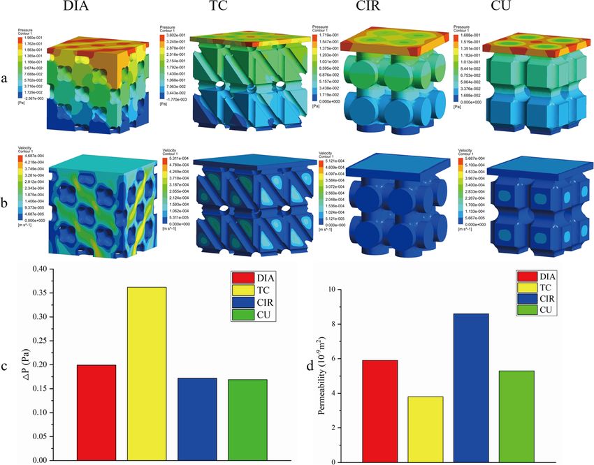
Deng et al. Journal of Biological Engineering (2021) 15:4 Page 3 of 13
Fig. 1 Schematic diagram of the design parameters of the four structures
π 2 8 measurement of scaffold parameters, which proves its
V CIR ¼ a3 − t a þ πt 3
4 4 reliability and accuracy [5, 17, 18, 20, 21].
The pore size of the four structures can be expressed Mechanical property of the scaffolds
by Eq. (2): Mechanical experiments were carried out according to
pffiffiffi the ISO-13314 standard. A rectangular scaffold (n = 5,
tTC ¼ 2‐ 2 a − D ð2Þ 10 × 10 × 12 mm) was used for the compressive strength
pffiffiffi experiments. A material universal testing machine
6 (WDW-300; Changchun Kexin Testing Instrument Co.,
tDIA ¼ a−D
3 Ltd.) was used for the mechanical experiments, as shown
tCU ¼ a − D in Fig. 2a. During the experiment, compression was per-
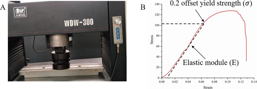
formed at a speed of 1 mm/min. The elastic modulus (E)
In the design, first, the strut diameter was calculated and compressive strength (σ) of the porous scaffold were
when the cell structure porosity was 65% and then the obtained from the stress-strain curve of the material.
value of the cell length was calculated when the pore The elastic modulus of the scaffold was calculated ac-
size was 650 μm and the strut diameter D was un- cording to the maximum slope in the elastic region of
changed. All scaffolds were printed using SLM technol- the stress-strain curve. The compressive strength of the
ogy. The 3D printing was carried out by using the scaffold was calculated by the 0.2% offset method, as
FS271M System of Sichuan Farsoon Turing Additive shown in Fig. 2b, which is the typical stress-strain curve
Manufacturing Technology Co., Ltd. The machine was of the DIA.
equipped with a 500 W laser with a spot size of 70 μm.
The layer thickness and scanning speed were 30 μm and Surgical procedure
300 mm/s, respectively. After completing the SLM In this study, a total of 24 adult New Zealand white rab-
process, all implants were heated in argon at 800 °C for bits (2.5–3.0 kg) from the Experimental Animal Center
2 h and then ultrasonically cleaned with ethanol and dis- of Southwest Medical University were selected. There
tilled water three times (15 min each time). were 12 females and 12 males. The temperature of the
breeding room is 24 °C, and the humidity is 60%. The
Characterization of the scaffolds rabbits have free access to water and food. The experi-
The micro-CT technique was used to analyze the struc- mental plan was approved by the Southwest Medical
ture of the porous titanium scaffold, and then University Laboratory Animal Protection and Welfare
Mimics21.0 (Materialise’s interactive medical image con- Committee in accordance with international standards.
trol system, Italy) software was used to reconstruct and Twenty-four rabbits were randomly divided into two
measure the scaffold and its surrounding bone tissue in groups according to the implantation time (6 weeks, 12
3D. Parameters such as the pore size of the scaffold, weeks). In each group, 12 rabbits with a total of 24 fe-
strut size, porosity and surface area were included. The murs were implanted with four different cylindrical scaf-
pore size, strut size, porosity and surface area of the folds (n = 6, φ5 × 8 mm). Intravenous injection of 3%
scaffold were measured. The data obtained via micro-CT pentobarbital sodium (30 mg/kg) under general
for the measurement of the scaffold parameters are ac- anesthesia and 0.5% lidocaine local anesthesia. After skin
curate with a small error. Moreover, a large number of preparation disinfection, a 3 cm longitudinal incision
studies in the literature have applied micro-CT for the was made in both femoral condyles for surgery. The skin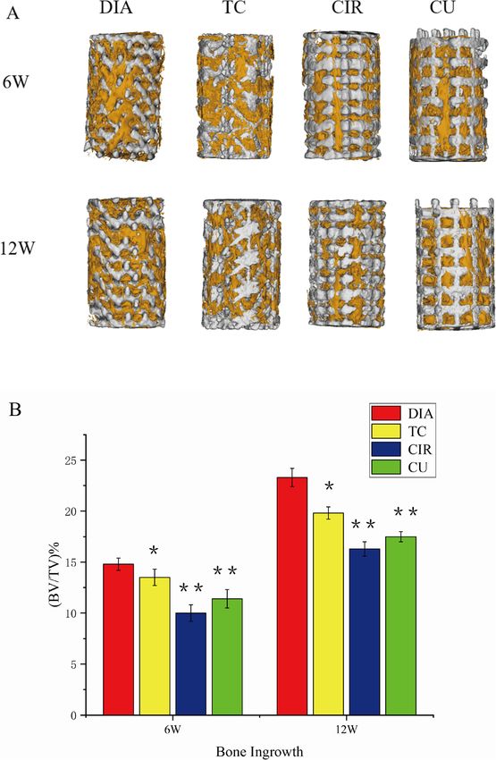
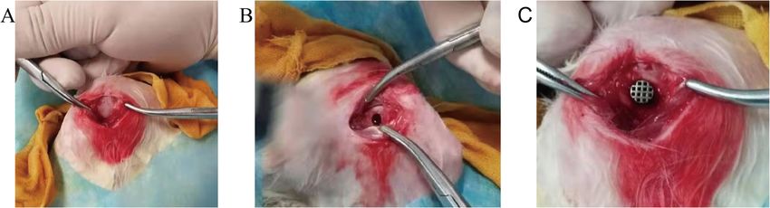
Deng et al. Journal of Biological Engineering       (2021) 15:4                                                                        Page 4 of 13

 Fig. 2 A Material universal testing machine; B DIA stress-strain curve

and subcutaneous tissue were cut to separate the mus-                       there was new bone tissue, microvascular tissue or fi-
cles, and the periosteum was cut to expose the femoral                      brous tissue inside the scaffold.
condyle (Fig. 3a). A hole with a diameter of 5 mm and a
depth of 8 mm was drilled in sequence on the lateral
side of the femoral condyle with a low-speed drill (Fig.                    Micro-CT analysis
3b). When drilling holes, physiological saline was used                     To assess the effectiveness of new bone formation, the
to reduce the temperature to prevent tissue necrosis                        rabbit femurs implanted with porous scaffolds were
caused by local high temperatures. After the drilling was                   scanned using micro-CT (Micro-CT100, SCANCO
completed, the scaffold was implanted (Fig. 3c), and the                    Medical AG). The scanning parameters were set as fol-
wound was sutured in turn. Three days after surgery,                        lows: X-ray source voltage = 90 kV; beam current =
intramuscular injection of cephalosporin antibiotics was                    200 μA; scanning resolution = 17.2 μm. After scanning the
used for anti-infective treatment. At 6 weeks and 12                        sample, the projection is reconstructed and segmented
weeks after the operation, the rabbits were sacrificed by                   into a binary image and further analyzed with Mimics
intravenous air injection. The femurs were removed,                         21.0 (Materialise, Belgium). The internal space of the scaf-
washed with formalin-fixed water, dehydrated with etha-                     fold and bone tissue growth into the scaffold were defined
nol, infiltrated and embedded, and the hard tissue was                      as the volume of interest, and the bone volume (BV) and
sectioned into 200 μm sections using an EXAKT                               total pore volume (TV) were measured by micro-CT for
E300CP hard tissue slicer. After grinding and polishing,                    further detailed data analysis. By calculating the ratio of
slices of approximately 70 μm were made. The slices                         BV to TV (BV/TV), the BT/TV value with higher bone
were stained by the HE staining method and observed                         growth performance was quantitatively evaluated, indicat-
under an optical microscope. We observed whether                            ing that more bone had grown into the scaffold.

 Fig. 3 a Exposure of the distal lateral condyle of the femur; b A defect (5 mm in diameter and 8 mm in depth) was drilled from the lateral
 femoral condyle of the rabbit at low speed; c Titanium scaffold implanted into the bone defect
Deng et al. Journal of Biological Engineering   (2021) 15:4                                                          Page 5 of 13

Histological evaluation                                               where v, L, and ΔP represent the inlet fluid flow velocity
The fixed femoral condyle was dehydrated in ethanol and then          (m/s), model length (m), and pressure difference (MPa),
embedded with methyl methacrylate, and a saw blade was used           respectively.
to cut a 50 μm thick section along the long axis of the cylin-          Using Ansys Fluent software, the CFD simulation
drical scaffold. After staining with 1.2% trinitrophenol and 1%       model was analyzed and calculated, as shown in Fig. 4.
acid magenta (Van-Gieson staining), the images were observed          During the calculation, the inlet velocity was set at 0.1
under a light microscope via fluorescence microscopy.                 mm/s, the outlet pressure was set at 0, the fluid density
                                                                      was set at 1050 kg/m3, and the viscosity was set at
CFD simulation                                                        0.0037 kg/m/s [24]. The extra fluid domain above the
The permeability, velocity and internal velocity stream-              structure was used to avoid boundary effects.
lines of the different scaffolds were evaluated by CFD.
Due to the symmetry of the structure, only 2 × 2 × 2                  Statistical analysis
units were used for analysis to save calculation time. As-            The analysis was performed using SPSS software (SPSS
suming that the fluid is incompressible, the Navier                   Inc., Chicago, Il, USA). All the data are expressed as the
Stokes equation [22] was adopted for calculation:                     mean ± standard deviation and were analyzed with one-
                                                                      way ANOVA. In all cases, the results are considered sta-
        θv                                                            tistically significant with a p-value less than 0.05.
    ρ      − u∇2 V þ ρðv  ∇Þv þ ∇p ¼ F; ∇:V ¼ 0                ð3Þ
        θt
                                                                      Results and discussion
where ρ, v, and μ represent the fluid density (kg/m3),                Characterization of the porous titanium scaffolds
velocity of fluid flow (m/s) and dynamic fluid viscosity              Figure 5a is an enlarged photo of the 3D printed titan-
(kg/m/s), respectively. ∇ is the del operator, and p and F            ium scaffold manufactured by SLM for the mechanical
represent the pressure (MPa) and force (N), respectively.             experiments. Figure 5b is an enlarged photo of the four
  The permeability K of the four structures was calcu-                cylindrical titanium scaffolds manufactured by SLM. Fig-
lated by Darcy’s law equation [23]:                                   ure 5c is an image obtained after the 3D reconstruction
                                                                      of the titanium scaffold. The printed scaffold has good
           v:u:L
    K¼                                                          ð4Þ   consistency with the 3D reconstruction model, and the
            ΔP                                                        aperture and scaffold size are well controlled and

 Fig. 4 Schematic diagram of the CFD simulation boundary conditions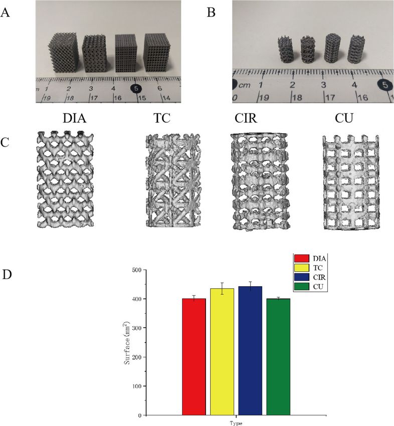
Deng et al. Journal of Biological Engineering     (2021) 15:4                                                                           Page 6 of 13

 Fig. 5 a Photo of a 3D printed titanium scaffold for the mechanical experiments; b Photo of the four cylindrical scaffolds for the in vivo
 experiments; c Micro-CT reconstruction of the porous titanium scaffold; d Surface area of four kinds of porous titanium scaffolds measured after
 3D reconstruction

uniform. Figure 5d shows the measured scaffold surface                      3D reconstruction, including the porosity, pore size,
area after the 3D reconstruction of the four porous ti-                     strut size and volume. The difference between the theor-
tanium scaffolds.                                                           etical and actual structural parameters is small, which
  In this experiment, the bone scaffold was fabricated                      means that the printed scaffold is of high quality. Small
using SLM technology [15, 20], through which complex                        values indicate that the quality of the printed scaffold is
3D metal parts can be manufactured with good control-                       high.
lability and repeatability. Therefore, the printed entity
conforms to the CAD model with minimal error, which                         Mechanical properties of the scaffold
is helpful for controlling the parameters of the porous                     Figure 6 shows the stress-strain curves of the four scaf-
structure and reducing the experimental error. At the                       folds. It can be seen from the figure that the scaffold
same time, relevant studies have shown that porous                          with the CIR structure is the lowest (49 MPa), which is
Ti6Al4V scaffolds have good biocompatibility and are                        caused by the fact that the strut is not homogeneous,
conducive to cell adhesion and proliferation [25], which                    and the weakest in the middle part. The yield strengths
also ensures the safety of our porous titanium scaffolds                    of the other three strut types are relatively close. Add-
implanted in animals. Table 1 shows the theoretical                         itionally, the elastic modulus and yield strength values of
values of the structural parameters of the porous titan-                    the four strut structures measured by the experiment are
ium scaffolds with four different topological structures                    shown in Table 2. Studies have shown that the elastic
and the actual values of the measured parameters after                      modulus of bone trabeculae ranges from 0.1–4.5 GPa
Deng et al. Journal of Biological Engineering         (2021) 15:4                                                               Page 7 of 13

Table 1 Structural parameters of the porous titanium scaffolds with four different topological structures
Sample              Porosity (%)                         Pore size (um)                   Unit size (mm)               Volume (mm3)
                    T                 A                  T               A                T            A               T           A
DIA                 64.5              64.8 ± 1.2         650             650 ± 2.9        1.6          1.6 ± 0.3       55.9        55.4 ± 0.4
TC                  65                65.3 ± 1.1         650             648 ± 4.1        1.86         1.84 ± 0.4      54.8        55 ± 0.4
CIR                 64.5              64.8 ± 1.2         680             678 ± 4.8        2            2.0 ± 0.1       55.7        56 ± 1.2
CU                  65                65 ± 1.1           660             663 ± 5.9        1.2          1.23 ± 0.1      55          56 ± 0.6
A Actual value; T Theoretical value

[26], and the yield strength of the proximal tibia and                          increased with increasing time. At 6 and 12 weeks, the
proximal femur ranges from 0.56–55.3 In this paper, ex-                         DIA, CU, TC, CIR and CIR models were in sequence
cept for the CIR structure, the yield strengths of all the                      from high to low, which was consistent with the ratio
other three structures exceed this range. The elastic                           between BV and TV (BV/TV) calculated by the quantita-
modulus of the four structures range from 1.9–4.2 GPa,                          tive analysis in Fig. 7b. Within 6 and 12 weeks, the BV/
which also well matches the elastic modulus of the host                         TV ratios were 15.2 and 23.1% for DIA, 13.7 and 19.1%
bone tissue. Therefore, the structure in this paper can                         for CU, 11.4 and 18.3% for TC, and 9.8 and 16.9% for
not only build an elastic modulus that matches the host                         CIR, respectively. Since we accurately controlled the por-
bone tissue but also ensure that the scaffold has a high                        osity and pore size of the porous scaffolds, the most
yield strength, which can be well applied in bone tissue                        likely reason for this osteogenic difference was the pore
scaffolds.                                                                      shape. Bael [15] found that according to in vitro experi-
                                                                                mental results, circular pore structures are more prone
Micro-CT analysis                                                               to pore blockage than non-circular pore structures. This
The titanium scaffold was implanted at the distal end of                        structural change may influence the delivery of nutrients
the rabbit femur, and the bone scaffold was removed for                         and oxygen inside the scaffold and thus affect bone
micro-CT measurements after 6 and 12 weeks. The for-                            growth. The pore shape may be one of the reasons that
mation of bone in the scaffold was evaluated by this                            the CIR structure has the least new bone. The DIA
technique. Figure 7a shows the 3D reconstruction image                          structure consists of 16 struts of equal length, each with
of the scaffold and new bone. As seen from the recon-                           an angle of 109.5°, which is similar to the intertrabecular
structed images, the bone tissue in the scaffold gradually                      angle of human cancellous bone measured by Natalie

  Fig. 6 Stress-strain curves of the four kinds of scaffold structures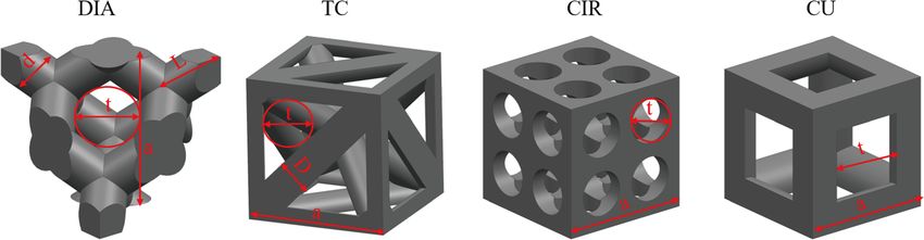
Deng et al. Journal of Biological Engineering     (2021) 15:4                                                                           Page 8 of 13

Table 2 Elastic modulus and yield strength of the four scaffold             [27]. Therefore, this trabecular bone-like structure may
structures                                                                  be beneficial for bone growth. As is known, the bone
Scaffold type     Elastic modulus(E/GPa)        Yield strength(σ /MPa)      scaffold porosity and void size have an important effect
DIA               2.1 ± 0.8                     106 ± 6                     on cell adhesion, proliferation, differentiation and new
TC                4.4 ± 0.3                     107 ± 3                     bone formation.
CIR               1.8 ± 0.5                     49 ± 2
CU                2.6 ± 0.1                     96 ± 5                      Histological analysis
                                                                            The animals were sacrificed in batches at 6 and 12
                                                                            weeks, and the samples harvested from the animals were
                                                                            fixed in 10% formalin, dehydrated with a series of etha-
                                                                            nol solutions (70, 80, 90, 95 and 100% X2) and subse-
                                                                            quently embedded in poly (methylmethacrylate)

 Fig. 7 a Micro-CT reconstruction of the distal femur of rabbits after 6 and 12 weeks of titanium scaffold implantation. White represents the bone
 scaffold, and yellow represents new bone. b The titanium scaffold was implanted in the distal femur of rabbits. *P < 0.05, **P < 0.001 compared
 with DIA
Deng et al. Journal of Biological Engineering (2021) 15:4 Page 9 of 13
(PMMA, Cool-Set-A, Aorigin, Chengdu, China). Sec- structures, the internal structure is relatively simple, so
tions (10–20 μm) were made with a diamond histological the velocity difference in the scaffold is not very large.
saw (SAT-001, Origin, Chengdu, China) and stained For the DIA and TC structures, due to their complex in-
with methylene blue (Sigma)/basic fuchsin (Sigma) for ternal structure, there is also a large velocity difference
histological observation. Bone growth was qualitatively [30]. The DIA velocity cloud shows that the velocity on
analyzed through the bone growth in the section dia- the side of the scaffold is significantly greater than the
gram, and the histological section diagram of the scaf- fluid flow inside the scaffold. This result indicates that
fold obtained after methylene blue (Sigma)/basic fuchsin the DIA structure can accelerate fluid flow inside the
(Sigma) staining is shown in Fig. 8. These section dia- scaffold structure, facilitating fluid flow to more areas of
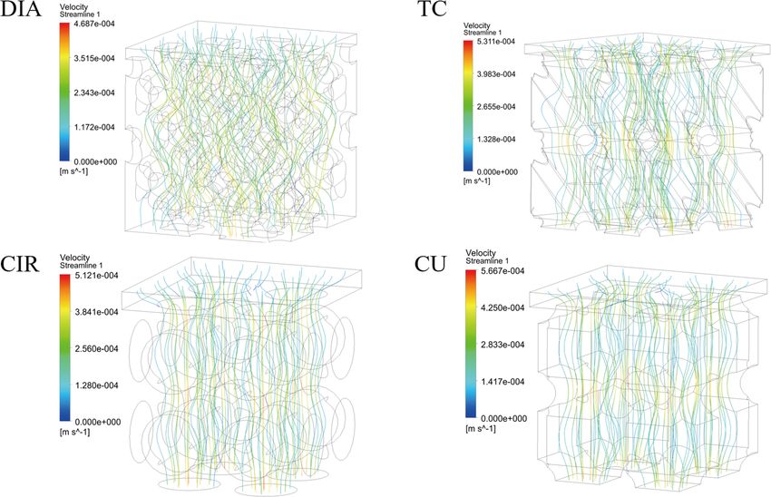
grams clearly show the formation of bone tissue in the the scaffold. Figure 9c shows the pressure difference △P
scaffold, and with increasing time, the amount of bone at the inlet and outlet of the four structures. It can be
tissue in the pores of the scaffold increased gradually. seen from the figure that the pressure drop difference in
The maximum amount of the new bone mass was exhib- the DIA, CIR and CU structures is not very great, while
ited in the DIA structure, and the minimum amount the pressure difference in the TC structure is more than
was in the CIR structure. This result is consistent with twice as large. This finding indicates that the internal
the qualitative and quantitative results obtained by obstruction of the TC structure has a large effect on the
micro-CT in Fig. 9 and Fig. 10. Therefore, according to fluid, which does not facilitate the flow of fluid inside
the results of the slices, we further verified the accuracy the structure or through more areas inside the structure.
of the experimental results. Figure 9d shows the permeability of the four structures,
which is calculated according to Eq. 4. The permeability
CFD analysis range of the proximal tibia is 0.467 × 10− 9 m2 to
The permeability and velocity of fluid flow in the in- 14.810− 9 m2 [31]. The permeability range of the four
ternal structure of the scaffold have a great influence on structures in this paper is 3.8 × 10− 9 m2 to 5.9 × 10− 9 m2.
the growth of bone tissue in the scaffold [28]. The fluid Therefore, the permeability is in line with the require-
flow inside the scaffold can provide necessary oxygen ments of bone tissue implantation.
and nutrients for the growth of cells. Excessive perme- Figure 10 shows the velocity flow diagrams for the four
ability is not conducive to the adhesion of cells on the scaffold structures. It can be seen from the figure that
surface of the scaffold, while too low of a permeability the velocity streamlines of the TC, CIR and CU struc-
cannot provide sufficient nutrients [29]. tures are relatively simple and flow through fewer areas
Figure 9a shows the pressure cloud diagram of the inside the structure. Compared to the other three struc-
scaffold. The pressure gradually decreases from the high- tures, the DIA structure has a low internal flow rate, and
est point of the inlet to the lowest point of the outlet. the lower speed allows cells to attach more easily to the
For different structures, the pressure is uniformly dis- surface of the scaffold, thus promoting bone growth in
tributed within the scaffold. Figure 9b shows the velocity the body. The speed of the other three structures at the
cloud map of the scaffold. For the CIR and CU intersection of the struts is significantly higher than that
Fig. 8 Histological sections of dehydrated embedded samples of the bone scaffolds obtained at 6 weeks and 12 weeks were stained. Red
represents the bone tissue, and black represents the scaffold. Original magnification: 10.0; scale bar: 1 mm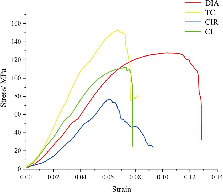
Deng et al. Journal of Biological Engineering        (2021) 15:4                                                 Page 10 of 13

 Fig. 9 Fluid simulation results of the four structures

at the pores, which can promote the migration of cells             humans. The size of bone defects, blood flow, local in-
to a deeper depth and make the cells less likely to adhere         flammatory response, osteocytes involved in bone forma-
to the surface of the struts. Therefore, the cells grew            tion, osteoblasts and various endogenous growth factors
more in the DIA structure than in the other three                  released by them, and mechanical stimulations all have
structures.                                                        an impact on bone growth. Therefore, in vivo experi-
   The pore structure is an important parameter that af-           ments are needed for further confirmation. In this study,
fects bone scaffolds and plays an important role in the            four kinds of porous titanium alloy scaffolds with differ-
mechanical properties of cell migration and adhesion tis-          ent structures made by SLM were selected, and four
sue formation and nutrient diffusion. There are many               kinds of scaffolds were implanted at the distal end of
in vitro experiments on the pore structure with different          rabbit femur to evaluate the growth of bone tissue
conclusions, and many studies have been limited to cell            in vivo to explore the optimal pore structure of bone
experiments [20, 32–34]. Our previous work [35] con-               growth. Based on CFD, the permeability, velocity and
firmed that we can print accurate titanium scaffolds               flow trajectory of the scaffold structure were calculated.
using SLM. It has been confirmed by cell experiments               The combination of in vivo experiments and CFD simu-
in vivo that titanium scaffolds have good biocompatibil-           lations reveals the causes of bone ingrowth in different
ity, which has also been confirmed in a large number of            structures, which provides a new theoretical basis for the
studies and can meet the normal adhesion and differen-             design of bone scaffolds in the future.
tiation requirements of cells. A cell culture is static,              Before the four scaffolds were implanted in vivo,
while the human environment is dynamic. Thus, cell                 mechanical experiments were conducted on these struc-
tests do not completely simulate bone growth in                    tures to measure their elastic modulus and yield strength
Deng et al. Journal of Biological Engineering      (2021) 15:4                                                 Page 11 of 13

 Fig. 10 Velocity flow diagrams for the four structures

values. According to the related literature, the elastic         lower speed can better promote cell adhesion to the sur-
modulus of trabecular bone is in the range of 0.1–4.5            face of the scaffold. Moreover, only when the cells stick
GPa, and the yield strength of the vertebrae, proximal           together can they proliferate further, thus facilitating
tibia and proximal femur ranges from 0.56–55.3 MPa.              bone growth in the body. However, the results of Bael
The results showed that the elastic modulus of the four          et al. showed that obtuse angles were more likely to
kinds of scaffolds was within the normal range, which            cause cell clogging than acute angles, and, in this paper,
could avoid the stress masking effect caused by a mis-           the TC structure was second only to the DIA structure.
match of the elastic modulus. The yield strength of the          The DIA struts have an angle of 109° between them. Ac-
four kinds of scaffolds met the strength requirements of         cording to its structural analysis, the DIA structure
orthopedic implants.                                             should grow into a poor structure, but in fact, the op-
   Through quantitative and qualitative analysis of the          posite is true. We believe that Bael’s research on the
new bone mass, we concluded that structural bone                 bone scaffold angle is limited to the 2D level, while the
growth in the DIA structure was the best and bone                DIA angle is measured in 3D, so this theory is not com-
growth in the CIR was the worst, which was further veri-         pletely applicable to the DIA structure. At the same
fied in the hard tissue sections. Compared with the re-          time, according to fluid mechanics analysis, the pressure
sults of the in vitro experiments conducted by Bael,             difference between the inlet and the outlet of the TC
circular pore structures are more prone to pore blockage         structure is more than twice that of the DIA, CIR and
than non-circular pore structures. One of the reasons            CU structures. This result indicates that the internal ob-
for this behavior is the decrease in nutrients and oxygen        struction of the TC structure is greater, which is not
transport inside the scaffold, which affects bone growth.        conducive to the flow of fluid inside the structure or
The second reason is that the fluid mechanics shows              through more areas inside the structure, so the delivery
that the DIA structure can accelerate fluid flow inside          of oxygen and nutrients will be relatively less. However,
the scaffold structure, which is beneficial for the fluid        the internal structure of TC is more complex than that
flow to more areas of the scaffold. At the same time, the        of CIR and CU, and the site of internal cell attachment
flow velocity inside the DIA structure is not large. The         is more than that of the latter two. At the same time, it
Deng et al. Journal of Biological Engineering         (2021) 15:4                                                                                Page 12 of 13

can be seen that the velocity streamlines of the TC, CIR                       Authors’ contributions
and CU structures are relatively close. Triangular holes                       All authors helped in drafting the manuscript. All authors read and approved
                                                                               the final manuscript.
seem to be more conducive to cell proliferation and dif-
ferentiation than the square and round holes, so the TC                        Funding
structure is better than the CIR and CU structures in                          This work was supported by the Applied Basic Research Project of Science
terms of bone growth. In summary, based on the in vitro                        and Technology Department of Sichuan Province (2020YJ0265) and the
                                                                               Sichuan University-Luzhou Government Strategic Cooperation Project (No.
and in vivo experiments, we conclude that the DIA                              2019CDLZ-17).
model demonstrated the best structural bone growth.
   At present, there are many topological structures used                      Availability of data and materials
                                                                               Not applicable.
in scaffold design. In this paper, four common structures
are selected, and a comparison of the results obtained is                      Ethics approval and consent to participate
limited to these four structures. In addition, the simula-                     Not applicable.
tion of blood flow by using computer fluid mechanics
cannot completely replace an in vivo situation, and the                        Consent for publication
                                                                               Not applicable.
data may be biased to some extent, so further accuracy
is needed in future studies.                                                   Competing interests
                                                                               The authors declare that they have no competing interests.

                                                                               Author details
Conclusion                                                                     1
                                                                                Department of Orthopaedics, The Affiliated Hospital of Southwest Medical
Via selective laser melting method, the structures of four                     University, Luzhou 646000, Sichuan, China. 2Sichuan Provincial Laboratory of
different kinds of porous titanium alloy scaffolds with a                      Orthopaedic Engineering, Luzhou 646000, Sichuan, China. 3School of
                                                                               Mechanical Engineering, Sichuan University, Chengdu 610065, Sichuan,
similar porosity (65%) and aperture size (650 μm) were                         China.
prepared and investigated through in vivo experiments
along with CFD analysis. Combined with existing re-                            Received: 21 October 2020 Accepted: 3 January 2021
search studies, the different structures of the bone in-
growth of bone scaffolds were analyzed and the                                 References
following conclusions were drawn:                                              1. Zehao J,Jing Z,Zhang T,Xiu P,Cai H, Wei Q, Fan D , Lin X,Song C, Liu Z.
                                                                                   Functionalization of 3D-printed titanium alloy orthopedic implants: a
                                                                                   literature review[J]. Biomedical Materials. 2020;15(5).
  1. SLM printing can print high-strength and low-                             2. Chen Q, Thouas GA. Metallic implant biomaterials. Mat Sci Engineering R-
     modulus bone scaffolds, with good application pros-                           Reports. 2015;87:1–57.
     pects in orthopedics.                                                     3. Frost HM. A 2003 update of bone physiology and Wolff's law for clinicians.
                                                                                   Angle Orthod. 2004;74(1):3–15.
  2. The pore structure has a great influence on bone                          4. Li L, Shi J, Zhang K, Yang L, Yu F, Zhu L, Liang H, Wang X, Jiang Q. Early
     growth. Among the four different pore structures,                             osteointegration evaluation of porous Ti6Al4V scaffolds designed based on
     the DIA structure demonstrated the best bone                                  triply periodic minimal surface models. J Orthopaedic Transl. 2019;19:94–
                                                                                   105.
     growth effect.                                                            5. Ouyang P, Dong H, He X, Cai X, Wang Y, Li J, Li H, Jin Z. Hydromechanical
  3. CFD analysis was performed, and the permeability,                             mechanism behind the effect of pore size of porous titanium scaffolds on
     flow rate and flow trajectory of the scaffold                                 osteoblast response and bone ingrowth. Mater Des. 2019;183.
                                                                               6. Maietta S, Gloria A, Improta G, Richetta M, De Santis R, Martorelli M. A
     structure were calculated. The results showed that                            further analysis on Ti6Al4V lattice structures manufactured by selective laser
     the internal fluid velocity difference in the DIA                             melting. J Healthcare Engineering. 2019;2019.
     structure was the smallest and the fluid flow                             7. Li J, Jansen JA, Walboomers XF, van den Beucken JJJP. Mechanical aspects
                                                                                   of dental implants and osseointegration: a narrative review. J Mech Behav
     trajectory was the longest in the scaffold, which was                         Biomed Mater. 2020;103.
     conducive to bone growth.                                                 8. Chen Z, Yan X, Yin S, Liu L, Liu X, Zhao G, Ma W, Qi W, Ren Z, Liao H, Liu M,
  4. This paper provides a new method for the research                             Cai D, Fang H. Influence of the pore size and porosity of selective laser
                                                                                   melted Ti6Al4V ELI porous scaffold on cell proliferation, osteogenesis and
     of porous scaffolds by combining computational                                bone ingrowth. Mat Sci Engineering C-Materials for Biological Applications.
     fluid dynamics analysis and in vivo experiments and                           2020;106.
     provides a new basis for the design of future                             9. Revilla-Leon M, Meyer MJ, Ozcan M. Metal additive manufacturing
                                                                                   technologies: literature review of current status and prosthodontic
     scaffolds.                                                                    applications. Int J Comput Dent. 2019;22(1):55–67.
                                                                               10. Onal E, Frith JE, Jurg M, Wu X, Molotnikov A. Mechanical properties and
                                                                                   in vitro behavior of additively manufactured and functionally graded
Abbreviations                                                                      Ti6Al4V porous scaffolds. Metals. 2018;8(4).
DIA: Diamond lattice unit; CFD: Computational fluid dynamics; SLM: Selective   11. Ran Q, Yang W, Hu Y, She X, Yu Y, Xiang Y, Cai K. Osteogenesis of 3D
laser melting                                                                      printed porous Ti6Al4V implants with different pore sizes. J Mech Behav
                                                                                   Biomed Mater. 2018;84:1–11.
                                                                               12. Weissmann V, Bader R, Hansmann H, Laufer N. Influence of the structural
Acknowledgments                                                                    orientation on the mechanical properties of selective laser melted Ti6Al4V
Not applicable.                                                                    open-porous scaffolds. Mater Des. 2016;95:188–97.
Deng et al. Journal of Biological Engineering (2021) 15:4 Page 13 of 13
13. Arjunan A, Demetriou M, Baroutaji A, Wang C. Mechanical performance of significantly affects human stem cell bone tissue engineering. J Cell Physiol.
highly permeable laser melted Ti6Al4V bone scaffolds. J Mech Behav 2008;214(1):166–72.
Biomed Mater. 2020;102. 34. Knychala J, Bouropoulos N, Catt CJ, Katsamenis OL, Please CP, Sengers BG.
14. Bidan CM, Kommareddy KP, Rumpler M, Kollmannsberger P, Fratzl P, Pore geometry regulates early stage human bone marrow cell tissue
Dunlop JWC. Geometry as a factor for tissue growth: towards shape formation and organisation. Ann Biomed Eng. 2013;41(5):917–30.
optimization of tissue engineering scaffolds. Advanc Healthcare Mat. 2013; 35. Wang S, Liu L, Li K, Zhu L, Chen J, Hao Y. Pore functionally graded Ti6Al4V
2(1):186–94. scaffolds for bone tissue engineering application. Mater Des. 2019;168.
15. Van Bael S, Chai YC, Truscello S, Moesen M, Kerckhofs G, Van Oosterwyck H,
Kruth IP, Schrooten J. The effect of pore geometry on the in vitro biological
behavior of human periosteum-derived cells seeded on selective laser- Publisher’s Note
melted Ti6Al4V bone scaffolds. Acta Biomater. 2012;8(7):2824–34. Springer Nature remains neutral with regard to jurisdictional claims in
published maps and institutional affiliations.
16. Rudrich U, Lasgorceix M, Champion E, Pascaud-Mathieu P, Damia C, Chartier
T, Brie J, Magnaudeix A. Pre-osteoblast cell colonization of porous silicon
substituted hydroxyapatite bioceramics: influence of microporosity and
macropore design. Mat Sci Engineering C-Materials for Biological
Applications. 2019;97:510–28.
17. Taniguchi N, Fujibayashi S, Takemoto M, Sasaki K, Otsuki B, Nakamura T,
Matsushita T, Kokubo T, Matsuda S. Effect of pore size on bone ingrowth
into porous titanium implants fabricated by additive manufacturing: an
in vivo experiment. Mat Sci Engineering C-Materials for Biological
Applications. 2016;59:690–701.
18. Otsuki B, Takemoto M, Fujibayashi S, Neo M, Kokubo T, Nakamura T. Pore
throat size and connectivity determine bone and tissue ingrowth into
porous implants: three-dimensional micro-CT based structural analyses of
porous bioactive titanium implants. Biomaterials. 2006;27(35):5892–900.
19. Karageorgiou V, Kaplan D. Porosity of 3D biomaterial scaffolds and
osteogenesis. Biomaterials. 2005;26(27):5474–91.
20. Zhang B, Pei X, Zhou C, Fan Y, Jiang Q, Ronca A, D'Amora U, Chen Y, Li H,
Sun Y, Zhang X. The biomimetic design and 3D printing of customized
mechanical properties porous Ti6Al4V scaffold for load-bearing bone
reconstruction. Mater Des. 2018;152:30–9.
21. Akiyama H, Morishima T, Takemoto M, Yamamoto K, Otsuka H, Iwase T,
Kabata T, Soeda T, Kawanabe K, Sato K, Nakamura T. A novel technique for
impaction bone grafting in acetabular reconstruction of revision total hip
arthroplasty using an ex vivo compaction device. J Orthop Sci. 2011;16(1):
26–37.
22. Vossenberg P, Higuera GA, van Straten G, van Blitterswijk CA, van Boxtel
AJB. Darcian permeability constant as indicator for shear stresses in regular
scaffold systems for tissue engineering. Biomech Model Mechanobiol. 2009;
8(6):499–507.
23. Gomez S, Vlad MD, Lopez J, Fernandez E. Design and properties of 3D
scaffolds for bone tissue engineering. Acta Biomater. 2016;42:341–50.
24. Sinha R, Le Gac S, Verdonschot N, van den Berg A, Koopman B, Rouwkema
J. Endothelial cell alignment as a result of anisotropic strain and flow
induced shear stress combinations. Sci Rep. 2016;6.
25. Li Y, Yang C, Zhao H, Qu S, Li X, Li Y. New developments of Ti-based alloys
for biomedical applications. Materials. 2014;7(3):1709–800.
26. Morgan EF, Bayraktar HH, Keaveny TM. Trabecular bone modulus-density
relationships depend on anatomic site. J Biomech. 2003;36(7):897–904.
27. Reznikov N, Chase H, Ben Zvi Y, Tarle V, Singer M, Brumfeld V, Shahar R,
Weiner S. Inter-trabecular angle: a parameter of trabecular bone architecture
in the human proximal femur that reveals underlying topological motifs.
Acta Biomater. 2016;44:65–72.
28. Ali D. Effect of scaffold architecture on cell seeding efficiency: a discrete
phase model CFD analysis. Comput Biol Med. 2019;109:62–9.
29. Melchels FPW, Tonnarelli B, Olivares AL, Martin I, Lacroix D, Feijen J, Wendt
DJ, Grijpma DW. The influence of the scaffold design on the distribution of
adhering cells after perfusion cell seeding. Biomaterials. 2011;32(11):2878–84.
30. Ma S, Tang Q, Feng Q, Song J, Han X, Guo F. Mechanical behaviours and
mass transport properties of bone-mimicking scaffolds consisted of gyroid
structures manufactured using selective laser melting. J Mech Behav
Biomed Mater. 2019;93:158–69.
31. Beaudoin AJ, Mihalko WM, Krause WR. Finite element modelling of
polymethylmethacrylate flow through cancellous bone. J Biomech. 1991;
24(2):127–36.
32. Bouet G, Marchat D, Cruel M, Malaval L, Vico L. In vitro three-dimensional
bone tissue models: from cells to controlled and dynamic environment.
Tissue Engineering Part B-Reviews. 2015;21(1):133–56.
33. Graziano A, D'Aquino R, Angelis MGC-D, De Francesco F, Giordano A, Laino
G, Piattelli A, Traini T, De Rosa A, Papaccio G. Scaffold's surface geometryYou can also read