Additive-manufactured Ti-6Al-4 V/ Polyetheretherketone composite porous cage for Interbody fusion: bone growth and biocompatibility evaluation in ...
←
→
Page content transcription
If your browser does not render page correctly, please read the page content below
Tsai et al. BMC Musculoskeletal Disorders  (2021) 22:171
https://doi.org/10.1186/s12891-021-04022-0

 RESEARCH ARTICLE                                                                                                                                   Open Access

Additive-manufactured Ti-6Al-4 V/
Polyetheretherketone composite porous
cage for Interbody fusion: bone growth
and biocompatibility evaluation in a
porcine model
Pei-I Tsai1†, Meng-Huang Wu2,3†, Yen-Yao Li4,5, Tzu-Hung Lin6, Jane S. C. Tsai1, Hsin-I Huang1, Hong-Jen Lai7,
Ming-Hsueh Lee8,9* and Chih-Yu Chen3,10*

  Abstract
  Background: We developed a porous Ti alloy/PEEK composite interbody cage by utilizing the advantages of
  polyetheretherketone (PEEK) and titanium alloy (Ti alloy) in combination with additive manufacturing technology.
  Methods: Porous Ti alloy/PEEK composite cages were manufactured using various controlled porosities. Anterior
  intervertebral lumbar fusion and posterior augmentation were performed at three vertebral levels on 20 female
  pigs. Each level was randomly implanted with one of the five cages that were tested: a commercialized pure PEEK
  cage, a Ti alloy/PEEK composite cage with nonporous Ti alloy endplates, and three composite cages with porosities
  of 40, 60, and 80%, respectively. Micro-computed tomography (CT), backscattered-electron SEM (BSE-SEM), and
  histological analyses were performed.
  Results: Micro-CT and histological analyses revealed improved bone growth in high-porosity groups. Micro-CT and
  BSE-SEM demonstrated that structures with high porosities, especially 60 and 80%, facilitated more bone formation
  inside the implant but not outside the implant. Histological analysis also showed that bone formation was higher in
  Ti alloy groups than in the PEEK group.
  Conclusion: The composite cage presents the biological advantages of Ti alloy porous endplates and the
  mechanical and radiographic advantages of the PEEK central core, which makes it suitable for use as a single
  implant for intervertebral fusion.
  Keywords: Additive manufacturing (3D printing), Ti, 6Al, 4 V (Ti alloy)/polyetheretherketone (PEEK) composite
  porous cage, porcine study

* Correspondence: maxwutmu@gmail.com; aleckc2424@gmail.com
†
 Pei-I Tsai and Meng-Huang Wu contributed equally to this work.
8
 Department of Neurosurgery, Department of Surgery, Chang Gung
Memorial Hospital, Chiayi 61363, Taiwan
3
 Department of Orthopaedics, School of Medicine, College of Medicine,
Taipei Medical University, Taipei, Taiwan
Full list of author information is available at the end of the article

                                        © The Author(s). 2021 Open Access This article is licensed under a Creative Commons Attribution 4.0 International License,
                                        which permits use, sharing, adaptation, distribution and reproduction in any medium or format, as long as you give
                                        appropriate credit to the original author(s) and the source, provide a link to the Creative Commons licence, and indicate if
                                        changes were made. The images or other third party material in this article are included in the article's Creative Commons
                                        licence, unless indicated otherwise in a credit line to the material. If material is not included in the article's Creative Commons
                                        licence and your intended use is not permitted by statutory regulation or exceeds the permitted use, you will need to obtain
                                        permission directly from the copyright holder. To view a copy of this licence, visit http://creativecommons.org/licenses/by/4.0/.
                                        The Creative Commons Public Domain Dedication waiver (http://creativecommons.org/publicdomain/zero/1.0/) applies to the
                                        data made available in this article, unless otherwise stated in a credit line to the data.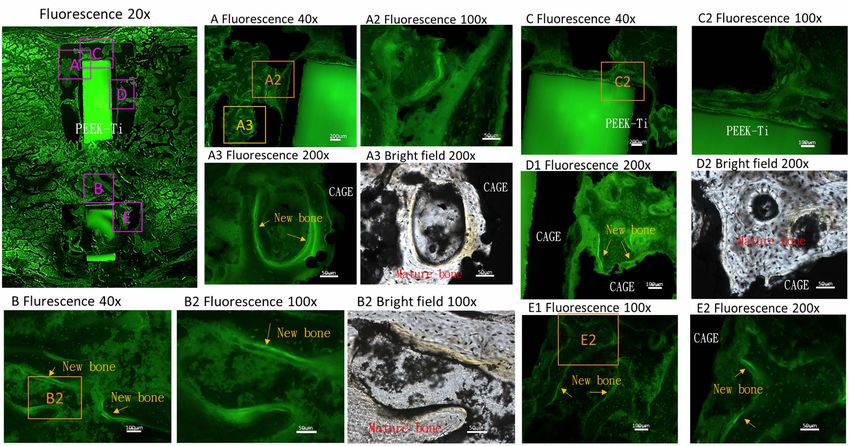
Tsai et al. BMC Musculoskeletal Disorders   (2021) 22:171                                                    Page 2 of 12

Background                                                   mass observation. Several studies have reported the use
Spinal fusion is a surgical treatment modality for several   of a composite material cage with both Ti and PEEK [7,
spinal diseases. Over an estimated 400,000 spinal fusions    12, 19]. However, no study has evaluated a porous struc-
are performed annually in the United States, and ap-         ture with different porosity rates.
proximately 2.8 million spinal fusions were conducted           We manufactured an innovative Ti-6Al-4 V (Ti alloy)/
from 2004 to 2015 [1]. Spinal fusion is the standard         PEEK composite porous cage through laser grooving,
treatment for 96% of patients with degenerative spinal       plasma spraying, and additive manufacturing (selective
diseases in the United States [2]. This surgery is           laser melting [SLM]) technology. By using the previously
intended to restore intervertebral disc height and achieve   developed laser grooving and plasma spraying technolo-
bony fusion between them. Several surgical procedures        gies [20], the shear bonding strength between Ti alloy
and fusion devices have been developed to achieve high       and the PEEK interface could be significantly increased.
fusion rates and optimize clinical outcomes.                 Moreover, using additive manufacturing technology, we
   Interbody techniques effectively restore disc height      could easily obtain different porosity rates at the end-
and lead to improved fusion rates [3]. Interbody cage        plate Ti alloy layer to facilitate bone ingrowth and strong
technology for spinal fusion was first proposed by Bagby     fusion constructs. We hypothesized that this porous
in 1988 [4]. Interbody cages have been designed as a         composite cage design facilitates bone fusion and leads
space holder implanted between adjacent bony endplates       to stronger fusion constructs compared with standard
and allows bone to grow through the space in order to        PEEK, Ti alloy, or nonporous Ti alloy/PEEK composite
achieve osseous integration of adjacent vertebral bodies     cages. The second objective is to identify the best poros-
[5–7]. A report noted that among patients undergoing         ity rate suitable for bone growth.
spinal fusion surgery for degenerative spondylolisthesis,
as many as 83% of procedures involved the use of an
interbody cage [8].                                          Methods
   Several materials have been used to manufacture inter-    Production of the additive-manufactured Ti-6Al-4 V/PEEK
body cages, of which polyetheretherketone (PEEK) and         composite porous cage
titanium (Ti) alloy are the most commonly used [7] be-       The innovative composite porous interbody cage was
cause of their excellent biocompatibility [9]. Ti and its    produced using the polymer core material PEEK,
alloys have been extensively used in the orthopedic in-      which is a favorable biomedical material with high
dustry since the 1940s [10]. Ti demonstrates excellent       strength and toughness. The surface of the PEEK
corrosion resistance in a clinical environment and is        polymer substrate was modified through laser groov-
widely used in additive manufacturing technology [7, 11,     ing to enhance the bonding strength of the subse-
12]. Its ability to enhance cell adhesion and osseointe-     quent coating layer (Fig. 1a and b). The surface was
gration is a crucial advantage for implanted orthopedic      then coated with a metallic (Ti alloy) interfacial layer
devices [9, 10]. However, Ti cages are radiopaque; there-    through low-temperature arc ion plating and plasma
fore, evaluating the bone fusion status over time through    spraying to ensure sufficient thickness of the metallic
standard clinical imaging modalities by clinicians be-       interface layer (300 μm).
comes difficult [13]. Furthermore, because of their high        Subsequently, a 3-mm-thick 3D Ti-6Al-4 V porous
elastic modulus, Ti cages result in high implant subsid-     scaffold was constructed above the metallic interfacial
ence rates [7, 14, 15].                                      layer with intended porosity parameters by using the
   PEEK is a hydrophobic polymer with a low elastic          SLM EOSINT M 270 model (EOS GambH-Electro Op-
modulus; thus, it can reduce the possibility of subsidence   tical Systems, Krailling, Germany).
into spinal endplates. PEEK cages were introduced in            The microstructure of the metallic interfacial layer was
the 1990s [16]. Unlike Ti cages, implanted PEEK cages        observed through multifunctional field-emission scan-
are radiolucent; however, their hydrophobic surface          ning electron microscopy (SEM), and its chemical com-
property makes protein absorption unlikely, resulting in     position was analyzed through SEM with energy-
poor cell adhesion and bone growth [17]. Animal studies      dispersive spectroscopy (SEM-EDS). The shear strength
have found that PEEK cages are encapsulated by a thin        of the bonding interface between the metallic layer and
fibrous tissue layer, which can inhibit implant–host bone    PEEK substrate exceeded 30 MPa (Fig. 1c).
growth, resulting in pseudarthrosis, nonfusion, implant         The results of the compressive mechanical test on the
migration, and subsidence [7, 18].                           composite porous interbody cage are shown in Fig. 1f
   Therefore, an ideal cage design should have the mater-    and Table 1, and those of the torsional mechanical test
ial advantages of both Ti and PEEK to achieve high           are shown in Fig. 1g and Table 2.
implant-bone affinity, facilitate bone growth, bone simi-       The porosity rate was defined using the following
lar biomechanical characters, and radiolucency for fusion    equation:
Tsai et al. BMC Musculoskeletal Disorders       (2021) 22:171                                                                            Page 3 of 12

    Fig. 1 Fabrication of the additive-manufactured Ti-6Al-4 V (Ti alloy)/polyetheretherketone (PEEK) composite porous cage. a Surface modification
    through laser grooving and plasma spraying makes the interfacial layer thicker than 300 μm. b Finished product of the Ti alloy/PEEK composite
    porous cage. c Shear strength of the bonding interface between the metallic layer and PEEK substrate exceeded 30 MPa. d Schematic of the
    porous structure with inset. e Schematic of the interporous distance. f Results of the mechanical compression test on the composite porous cage.
    g Results of the mechanical torsion test on the composite porous cage

Table 1 Results of the compressive mechanical test on the                     Table 2 Results of the torsional mechanical test on the
composite porous interbody cage                                               composite porous interbody cage
Porosity rate (%)             Yield load (N)            Stiffness (N/mm)      Porosity rate (%)      Stiffness (Nm/degree)       Yield moment (Nm)
0                             > 23,000                  35,420.96             0                      7.12                        41.61
40                            > 23,000                  30,831.72             40                     3.59                        26.37
60                            > 23,000                  29,654.86             60                     2.47                        19.66
80                            7047.09                   7374.72               80                     1.63                        11.13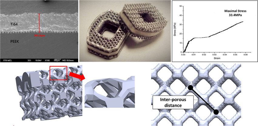
Tsai et al. BMC Musculoskeletal Disorders      (2021) 22:171                                                                Page 4 of 12


              Di porous                                                 Biotech Co., Ltd., New Taipei City, Taiwan) in implanted
     P% ¼ 1 −            100%                                          levels. All pigs were kept in single pens throughout the
               Dsolid
                                                                        6-month observation period and were subsequently eu-
where P% is the porosity rate, Di_porous is the measured                thanized. Tetracycline (20 mg/kg; SIGMA-Aldrich,
density of the metallic layer (measured mass divided by                 Merck Group, Germany) was injected intravenously at 4
measured volume), and Dsolid is the density of the metal-               and 2 weeks before euthanasia to label bone growth.
lic layer in the solid condition. The parameters of differ-                The pigs were euthanized under deep anesthesia with
ent porosity rates are listed in Table 3. Schematics of the             intravenously injected KCl (1–2 mEq/kg). Plain radio-
porous structure and interporous distance are illustrated               graphs of anteroposterior and lateral views and com-
in Fig. 1d and e. Based on these parameters, composite                  puted tomography (CT) of the lumbosacral spine were
cages with metallic layers of different porosities were                 taken at euthanasia. The whole lumbar spinal column
produced. The geometric parameters of metallic and                      from L1 to L7 was removed en bloc, stripped of the soft
composite cages in this study were derived from the                     tissue, transported to the laboratory, and stored at −
commercialized PEEK cage (Anterior Cervical Interbody                   20 °C for further examination. The pigs were bred for
Fusion Cage®, BAUI biotech, New Taipei City, Taiwan).                   scientific purposes and handled according to the regula-
                                                                        tion of the Institutional Animal Care and Use Commit-
Study design                                                            tee (IACUC: PIG-106022) on animal experimentation.
This animal study was approved by the Ethics Commit-
tee of the Biomedical Technology and Device Research                    Surgical methods
Laboratories of Industrial Technology Research Institute                Before anesthesia, the pigs were premedicated intramus-
in accordance with National Animal Welfare Legislation                  cularly with 5 mg/kg Zoletil 50 (Zolazepam + Tileta-
(Approval No. PIG-1040106), and the study protocol                      mine) + 2.2 mg/kg Xylazine for induction. After
conformed to the National Institute of Health guidelines                orotracheal intubation, anesthesia was maintained
for the use of laboratory animals. Twenty 5-month-old                   through the inhalation of isoflurane (1.5%). Cephalo-
female pigs (Lanyu 50, Taiwan) from different litters,                  sporin (1 g, intravenously) was administered 30 min be-
weighing 35–45 kg, were used in this study following                    fore surgery as a prophylactic antibiotic.
Zou et al.’s protocol [21]. All the pigs were obtained                    Under aseptic conditions, the autologous bone graft
commercially from PigModel Animal Technology Co.,                       was harvested from the right iliac crest with the pig
Ltd. (Miaoli, Taiwan). Each pig underwent anterior                      placed in a prone position and prepared as morselized
intervertebral lumbar fusion at three levels: L2–L3, L4–                cancellous bone chips. Under fluoroscopic control, the
L5, and L6–L7. Each level was randomly implanted with                   intervertebral space in implanted levels was identified
one of the five test cages. Each of the five groups com-                before surgical intervention. The facet joints of the
prised 12 specimens. In the first group, we tested a com-               neighboring vertebrae at this level were exposed through
mercialized pure PEEK interbody device with an                          a posterior midline incision and paraspinal bilateral
autologous iliac crest bone graft (PEEK_NonP, group 1).                 intramuscular approach. Pedicle screws (5 mm in diam-
In the second group, a Ti alloy/PEEK composite cage                     eter and 30 mm in length) were inserted into the neigh-
with nonporous Ti alloy endplates embedded with an                      boring vertebrae transpedicularly. The incision in the
autologous iliac crest bone graft was tested (Comp_                     back was carefully sutured and the pigs were closely
NonP, group 2). The third, fourth, and fifth groups used                cared for 1 month to allow complete recovery. After the
composite cages embedded with an autologous iliac crest                 pigs’ condition become stable, we performed the 2nd
bone graft with porosities of 40, 60%, or 80% on both Ti                stage operation. With the pigs placed in the left decubi-
alloy endplates (Comp_40%P [group 3], Comp_60%P                         tus position, a retroperitoneal anterior approach was
[group 4], and Comp_80%P [group 5]). Each fusion seg-                   used. The rectus abdominis muscle and its sheath were
ment was additionally secured with pedicle screws                       incised and retracted. The innermost layer, the fascia of
(Lumbar Trans-Pedicle Screw Fixation System®; Wiltrom                   transverse abdominis, was carefully dissected to prevent

Table 3 Unit porous size, interporous distance, total volume, and total surface area of the cage at different porosities
Porosity rate    Unit porous size       Interporous distance   Total volume of cage materials   Total surface area   Young’s modulus
(%)              (mm3)                  (mm)                   (mm3)                            (mm2)                (GPa)
0                Nil                    Nil                    600                              631                  1.53
40               0.23                   0.40                   380                              2391                 1.33
60               0.23                   0.31                   300                              2406                 1.28
80               0.23                   0.22                   190                              2137                 0.32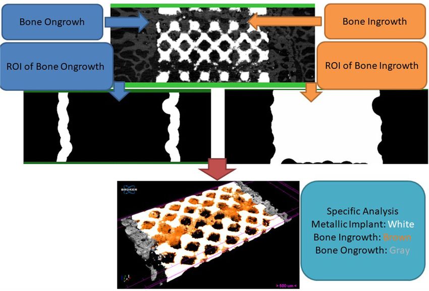
Tsai et al. BMC Musculoskeletal Disorders   (2021) 22:171                                                   Page 5 of 12

damage to the peritoneum lying immediately under-             as illustrated in Fig. 2. The inner bone was defined by
neath. After the peritoneum and its contents were sepa-       the bone formed interior to the surface of the implant
rated and retracted, the quadratus lumborum and psoas         (the doughnut body). 3D visualization was performed
major muscles could be viewed. The anterior lumbar            using Avizo software (Version 9.4, Thermo Fisher Scien-
spine was easily identified by its thick and shiny anterior   tific, MA, USA).
longitudinal ligament. After the ligation and cutting of
segmental vessels, the L2–L3, L4–L5, and L6–L7 inter-         Backscattered-Electron SEM
vertebral discs were excised together with the cranial        Three specimens were retrieved from each group and
and caudal endplates, ring apophysis, and part of the an-     scanned using backscattered-electron SEM (BSE-SEM)
terior longitudinal ligament. Thereafter, the bone graft      at 6 months postoperatively. The specimens were decal-
was morselized and packed into the central holes of the       cified before the procedure, embedded using Technovit
respective interbody cage devices. The fusion device–         9100 (Kulzer, Wehrheim, Germany), and then cut into
bone graft complexes were then implanted at each inter-       thin 1-mm slices. The slices were carefully polished and
vertebral disc. After insertion of the three implants, the    coated with carbon for BSE-SEM (DSM940; Carl-Zeiss
abdominal muscles and the rectus abdominis sheath             AG, Oberkochen, Germany) analysis. Multiple images
were carefully sutured, and the skin was closed using         were merged using Photoshop CC (Adobe, San Jose, CA,
running sutures. Prophylactic cephalosporin (1.0 g, intra-    USA). We then converted images into grayscale and an-
venously) and analgesic ketorolac (30 mg, intramuscu-         alyzed them using the 2D analysis function of CTAn
larly) were administered before and immediately after         software (Bruker Skyscan, Konitch, Belgium). We de-
surgery. All pigs were kept in individual pens and fed a      fined the implant area as a region of interest (bone in-
normal diet containing 1.4% calcium and 0.7% phos-            growth area). Next, we expanded the bone ingrowth area
phorus (percent of food weight). Pain control medication      by approximately 500 μm and then excluded the bone
was administered for 7 days postoperatively (400 mg ibu-      ingrowth area. The surrounding area was defined as the
profen, two tablets/day) and as required afterward.           bone ongrowth area. Morphometric indices of ingrowth
                                                              area, ongrowth area, and total area (ingrowth +
Micro-CT analysis                                             ongrowth) were analyzed.
After euthanasia, five specimens were retrieved from
each group and scanned using micro-CT (Skyscan 1272®          Histological analysis
at 8-μm/pixel, Bruker Micro-CT, Kontich, Belgium). A          Four specimens were retrieved from each group for
360° scan with a high voltage of 90 kVp, current of           histological analysis at 6 months postoperatively. All
111 μA, and output of 10 W was conducted. Image re-           these harvested samples were fixed in 10% formalin for
construction was performed using a graphics processing        14 days and sequentially dehydrated with increasing con-
unit-based reconstruction software, GPU-NRecon. Ring-         centrations of ethanol (70, 95, and 100%) for at least 1
artifact and beam-hardening correction were also per-         day and infiltrated for 5 days with polymethylmethacry-
formed using GPU-NRecon. The reconstructed cross              late. After embedding, the samples were cut horizontally,
sections were reoriented, and regions of interest (ROIs)      perpendicular to the axis of bony endplates, at the level
were further selected. Automatic thresholding and 3D/         of the respective bone–implant interfaces. The sections
2D structure and pore analyses were performed using           were cut to approximately 150 μm in thickness by using
CTAn software. We performed the analysis with 1.4-mm          an IsoMet™ Low Speed saw (Buehler, Lake Bluff, IL,
(113 slices) images. Metallic structure and bone were         USA) and ground to 60 μm with a grinding and polish-
separately isolated by the difference of X-ray absorption     ing machine. The ground sections were then stained
(Hounsfield Units, HU). The border of metallic structure      with Sanderson’s Rapid Bone Stain (Dorn & Hart Micro-
was calculated by CTAn software using shrink-warp al-         edge Inc., Loxley, AL, USA) and then counterstained
gorithm. ROIs of bone ongrowth was defined as 0–              with acid fuchsin. All bone–implant interfaces were ex-
500 μm around metallic implant border. ROIs of bone           amined carefully under a light microscope. In addition,
ingrowth was defined as the area inside metallic implant      the sections were examined through fluorescence mi-
border. Tissue volume (TV, mm3), bone volume (BV,             croscopy to identify new bone formation, which was la-
mm3), percent bone volume (BV/TV, %), bone surface            beled with tetracycline.
(BS, mm2) area, and bone surface area per total volume
(BS/TV, 1/mm) were measured 0–500 μm above the me-            Statistical analysis
tallic implant bone. With the nonporous implant as a          All experimental data are presented as the mean ± stand-
template, the outer bone was defined by those exterior        ard deviation, with values from more than three experi-
to the nonporous implant surface (including the bone          ments. The Wilcoxon rank sum test and Fisher’s exact
outside the doughnut and bone of the doughnut hole),          test were used for nonparametric analysis. Data with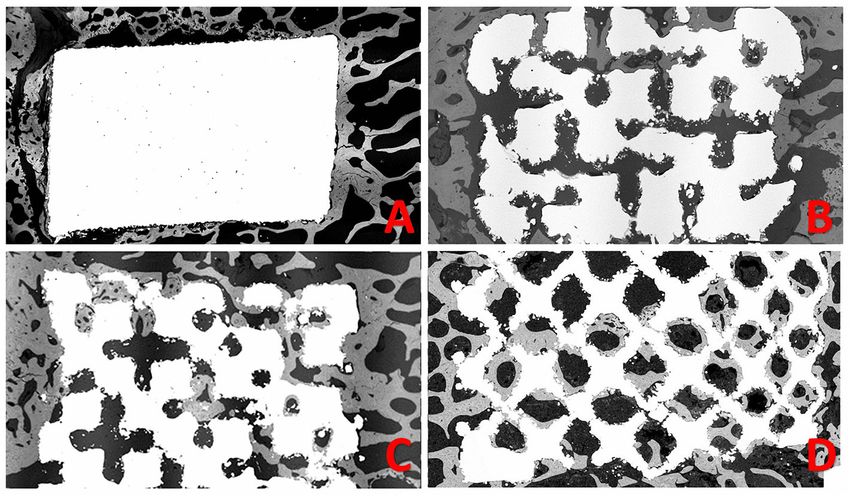
Tsai et al. BMC Musculoskeletal Disorders   (2021) 22:171                                                                        Page 6 of 12

 Fig. 2 The ROIs (region of interest) of bone ongrowth analysis and bone ingrowth analysis were shown. ROI of bone ongrowth was defined as
 0–500 μm around metallic implant border. ROI of bone ingrowth was defined as the area inside metallic implant border. The border was
 calculated by computer using shrink-warp algorithm

more than two groups were compared through one-way                       metal–PEEK interfacial layer formed a favorable bonding
analysis of variance and Tukey’s post hoc test for re-                   structure. In addition to the shear strength test, com-
peated measures. The correlation was examined as Pear-                   pression and torsion mechanical tests results according
son correlation and Spearman correlation; p < 0.05 was                   to ASTM2077 were shown in Fig. 1f and g and Tables 1
considered statistically significant. The power value was                and 2.
set to 0.8. Sample size calculation showed that the ani-                   The SEM analysis demonstrated superior cell growth
mal study required 11 in each group based on data by                     in the higher porosity group (Fig. 3). These findings sug-
Zou et al. [21]. Statistical analysis was performed using                gest that the increase in porosity from 40 to 60% in-
PASW software (version 18.0; SPSS, Chicago, IL, USA).                    creased the total surface area, and the larger surface area
                                                                         facilitated cell growth, differentiation, and attachment.
Results                                                                  Compared with the nonporous testing block, high-
In vitro mechanical analysis of the composite cage                       porosity cages have higher surface areas (from 40 to
The Ti alloy/PEEK composite cage for interbody fusion                    60%); therefore, cells may require more time to occupy
is composed of a new hybrid material with a multilayer                   these surfaces and demonstrate growth arrest through
structure on both bony contact surfaces and a PEEK                       contact inhibition.
core substrate (Fig. 1a and b).
  The shear strength of the interface layer of the hybrid                Micro-CT analysis
implant was measured using an ASTM D1002 tensile                         Micro-CT was used to evaluate bone formation be-
test piece developed using the SLM process. As shown                     tween the implant and bone tissue. Compared with
in Fig. 1c, when the thickness of the Ti alloy interfacial               PEEK and nonporous cages, the porous composite
layer was 301.9 μm, the bonding strength of the laser-                   cage (irrespective of the porosity rate) demonstrated
grooved interface layer reached 33.4 MPa. Thus, the                      significantly higher total and outer BV/TV at 6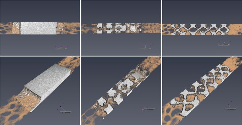
Tsai et al. BMC Musculoskeletal Disorders    (2021) 22:171                                                                Page 7 of 12

 Fig. 3 Scanning electron microscopy images of Ti-tested blocks with different porosities

months postoperatively at the bone–implant interface                        bone formation inside the implant; however, differences
(Fig. 4a and b). This finding suggests that the Ti im-                      in bone formation outside the implants were nonsignifi-
plant recruited more bone than did PEEK. However,                           cant between the groups.
the inner BV/TV significantly increased with the por-
osity rate (Fig. 4c). These findings suggest that the in-                   Histological analysis
creased porosity rate resulted in increased bone                            Compared with Ti alloy groups, bone formation at the
formation within the implant but not outside the im-                        bone–implant interface was lower in the PEEK group
plant (Fig. 5b, c, e, and f).                                               (Fig. 7a and b). Similar results were obtained from
  The bone surface density (BS/TV) represents the bone                      tetracycline-labeled bone fluorescence microscopy (Fig.
at the surface of the implant. Higher BS/TV suggests                        7e and f). The gap between the two surfaces was larger
more bone growth close to the defined implant surface                       in the PEEK group than in the Ti alloy group. As shown
area. As shown in Fig. 4d–f, composite cages with 60                        in Fig. 7a and e, bone formation appeared to encapsulate
and 80% porosity exhibited significantly higher total and                   the implant rather than grow inside the implant. By con-
inner BS/TV than did the other groups, suggesting that                      trast, the Ti alloy group had superior bone and implant
most of the formed bone was close to the porous struc-                      contact; the bone and implant gap was much smaller
ture (inside the implant) rather than outside the implant.                  and sometimes even difficult to identify (Fig. 7b and f).
  BSE-SEM analysis revealed results similar to those ob-                      Histological analysis (Fig. 7c and d) as well as
tained from 3D micro-CT analysis (Fig. 6).                                  tetracycline-labeled bone fluorescence microscopy (Fig.
  In summary, our micro-CT and BSE-SEM results                              7g and h) revealed bone growth on the porous structure.
demonstrated that structures with higher porosity, espe-                      Figures 7 and 8 show tetracycline-labeled new bone
cially those with 60 and 80% porosity, facilitated more                     growth into the space of the porous Ti structure,
Tsai et al. BMC Musculoskeletal Disorders    (2021) 22:171                                                                            Page 8 of 12

 Fig. 4 Quantitative analyses using micro-CT. a Total percent bone volume to total volume (total BV/TV) (%). b Outer percent bone volume to
 total volume (outer BV/TV) (%). c Inner percent bone volume to total volume (inner BV/TV) (%). d Total percent bone surface to total volume
 (total BS/TV) (1/mm). e Outer percent bone surface to total volume (outer BS/TV) (1/mm). f Inner percent bone surface to total volume (inner BS/
 TV) (1/mm). The groups were as follows: commercialized PEEK cage group (Anterior Cervical Interbody Fusion Cage®, BAUI biotech, New Taipei
 City, Taiwan) and composite Ti alloy/PEEK cage groups including nonporous Comp_NonP composites with 40%-, 60%-, and 80%-porosity
 endplates (Comp_40%P, Comp_60%P, and Comp_80%P, respectively) [* p < 0.05 between PEEK and other groups; # p < 0.05 between
 Comp_NonP group and other porous groups; % p < 0.05 between Comp_40%P and porous groups (Comp_60%P and Comp_80%P); and p < 0.05
 between Comp_60%P and Comp_80%P groups]

 Fig. 5 Representative images of micro-CT. Comp_NonP (a and d), Comp_60%P (b and e), and Comp_80%P (c and f). The black arrows indicate
 bone ongrowth and white arrows indicate bone ingrowth. Scale bar = 1 mm
Tsai et al. BMC Musculoskeletal Disorders (2021) 22:171 Page 9 of 12
Fig. 6 Representative backscattered-electron scanning electron microscopy images of Comp_NonP (a), Comp_40%P (b), Comp_60%P (c), and
Comp_80%P (d)
indicating peri-implant osteogenesis. However, because PEEK substrate. This shear strength is much higher than
of the qualitative nature of the histological analysis, we those previously reported [7, 9, 13, 19]. In addition, dif-
were unable to compare the amount of bone formation ferent Ti alloy porous structures can be easily manipu-
between different porosity rates. lated above the solid interface layer in the additive
In summary, bone formation in the Ti alloy groups manufacturing process to meet individual requirements.
was vastly superior to that in the PEEK group, with 60 PEEK cages have been widely used for spinal fusion
and 80% porosities being most beneficial for bone operations [9, 16, 18, 22]. Their advantages include
formation. radiolucency and low elastic modulus [9, 14, 16, 18].
Our experimental results are highly compatible with
Discussion those of previous studies examining PEEK cages packed
We developed a new porous Ti-6Al-4 V/PEEK compos- with the iliac bone graft [18, 23, 24]. However, PEEK
ite interbody cage. The innovative interfacial construc- cages have exhibited inferior implant–host bone growth
tion resulted in a high shear strength of more than 30 because of their chemically inert character, resulting in
MPa of the bonding interface between the Ti alloy and pseudarthrosis, nonfusion, implant migration, and
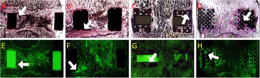
Fig. 7 Histological analysis and fluorescence microscopy. Sections a–d were stained with Sanderson’s Rapid Bone Stain and counterstained with
acid fuchsin (RBS). Sections E–H were examined with fluorescence microscopy to identify new bone formation labeled with tetracycline. A and E:
PEEK cage; B and F: Ti alloy nonporous cage; C and G: Ti alloy/PEEK composite cage with 60% porosity; and D and H: Ti alloy/PEEK composite
cage with 80% porosity. A and E: white arrows indicate a gap between the bone and implant. B and F: white arrows denote close contact
between the bone and implant, with new bone formation on the interface. C, D, G, and H: white arrows represent bone growth into the porous
structure of the implantTsai et al. BMC Musculoskeletal Disorders (2021) 22:171 Page 10 of 12 Fig. 8 Histological analysis of bone sections by using tetracycline through fluorescence and bright-field microscopy. New bone formation was easily identified inside the porous structure of the implant (Pig No. 14, L1/2, Ti alloy/PEEK composite cage with 60% porosity). Areas are picked-up by observed obvious bone ingrowth subsidence [7, 18, 25]. These shortcomings can be over- the main difference was derived from the bone come by coating bioactive substances at the bone- growth into the implant; this is evidenced by the contact surface layers of PEEK cages while maintaining significantly higher inner BV/TV in the 60%- and their advantages [7, 12, 13]. Ti alloy is one of the most 80%-porosity groups. By contrast, differences in common metals used with PEEK cages [26], and porous outer BV/TV between the groups were nonsignifi- Ti implants create an osteoconductive environment by cant. In addition, we compared the BS/TV between providing not only immediate stability resulting from the groups. Compared with BV/TV, BS/TV more interfacial friction but also long-term bony ongrowth directly indicates bone accumulation closer to the and ingrowth [7, 25]. implant surface. The results clearly demonstrated In the present study, in vivo experiments demon- significantly higher total and inner BS/TV in the strated favorable bone growth on Ti implants. Higher high-porosity groups (60 and 80%) than in the PEEK porosity rates led to larger total surface area and facili- and nonporous groups, but the outer BS/TV in each tated larger amount of bone formation within the porous group was not significantly different. All these find- structure, new bone formation can also be clearly identi- ings suggest that the majority of bone growth in the fied in the porous structure. In addition, SEM analysis porous groups was into the implant instead of at demonstrated superior cell growth in the higher porosity the outermost surface of the implant. Moreover, the group. bone growth close to the implant was superior on In the porcine model, significantly superior bone the Ti alloy surface to that on the PEEK surface. ingrowth into porous-structure composite cages was Histological analysis results revealed new bone for- observed. Compared with the PEEK and nonporous mation with calcium deposition within the porous Ti alloy groups, the porous composite cage groups structure of the composite cage. For the PEEK im- demonstrated superior bone growth in micro-CT plant, the gap between the implant and bone was and histological analyses. According to micro-CT larger than that for Ti alloy implants. This result is analysis, the BV/TV was significantly higher in the compatible with a previous finding that the hydro- high-porosity (60 and 80%) groups than in the PEEK phobic surface property of PEEK makes protein ab- and nonporous groups, indicating greater bone vol- sorption difficult and results in poor cell adhesion ume accumulation (bone growth) in the high- and bone growth [17]. By contrast, the Ti alloy cage porosity composite cage group. More specifically, demonstrated close contact between the implant and
Tsai et al. BMC Musculoskeletal Disorders   (2021) 22:171                                                                 Page 11 of 12

bone. Even in the absence of a porous structure,            solution for intervertebral fusion surgery and can be
clearly identifying the gap between the bone and im-        further developed for clinical use.
plant interface was difficult. For Ti alloy/PEEK com-
posite cages with a porous structure, bone growth           Supplementary Information
into the porous structure was clearly identified. As        The online version contains supplementary material available at https://doi.
                                                            org/10.1186/s12891-021-04022-0.
shown in Fig. 8, tetracycline-labeled new bone
growth into the space of the porous Ti structure
                                                             Additional file 1.
clearly indicated peri-implant osteogenesis. Peri-
                                                             Additional file 2.
implant osteogenesis is a multistep process that in-
                                                             Additional file 3.
cludes osteoblast adhesion, proliferation, and differ-
                                                             Additional file 4.
entiation and involves the production of specific
                                                             Additional file 5.
proteins and deposition of calcium phosphate in the
                                                             Additional file 6.
extracellular matrix [7, 27]. Our histological analysis
                                                             Additional file 7.
demonstrated osteogenic incorporation into the por-
                                                             Additional file 8.
ous structure of the porous composite cage. This re-
                                                             Additional file 9.
sult explains a previous micro-CT analysis finding of
a much larger inner BV/TV and BS/TV for porous
                                                            Abbreviations
cages. In summary, bone ingrowth into the porous            PEEK: Polyetheretherketone; Ti: Titanium; Ti-6Al-4 V: Titanium alloy;
composite cage enhanced host-bone implant                   CT: Computed tomography; BSE-SEM: Backscattered-electrons scanning
incorporation.                                              electron microscope; TV: Tissue volume; BV/TV: Bone volume, percent bone
                                                            volume; BS: Bone surface; BS/TV: Bone surface area per total volume
  Although our study provided promising results, it
has some limitations. First, the study was not per-         Acknowledgements
formed in an upright vertebral system. An in vitro          We would like to thank Hong-Jen Lai and Hsin-Hsin Shen (Material and
                                                            Chemical Research Laboratories, Industrial Technology Research Institute,
mechanical test in our previous work showed suffi-          Chutung, Hsinchu County, Taiwan) for their technical support of this study.
cient mechanical strength of the composite implant
[20], and no mechanical failure was noted in the            Authors’ contributions
                                                            IT, MHW, YYL, and MHL conceived the study. PIT, THL, JSCT, HJL, and CYC
present porcine study. However, future clinical stud-       designed the methodology; PIT, MHW, YYL, MHL, and CYC validated the
ies should validate the mechanical performance of           method; YMH and HIH conducted the formal analysis; MHL and CYC
the composite implant in the upright vertebral sys-         obtained the resources; PIT, MHW, and MHL performed data curation; TZL,
                                                            JSCT, YMH, HIH, and CYC prepared the original draft; PIT, MHW, and CYC
tem. Second, our results revealed the optimal com-          reviewed and edited the manuscript; TZL, JSCT, YMH, HIH, and CYC
promise between mechanical strength and bone                contributed to visualization; YYL, MHL, and CYC supervised the study; YYL
growth when the Ti alloy/PEEK composite cage with           and MHL contributed to project administration; PIT, YYL, and MHL assisted in
                                                            funding acquisition. All authors have read and agreed to the final version of
60% porosity was used. However, whether 60% por-            the manuscript.
osity is the optimal condition is unclear, and more
detailed analyses are required to identify the optimal      Funding
                                                            This study was supported by grants from Chiayi Chang Gung Memorial
porosity for bone growth and mechanical strength.
                                                            Hospital (Yen-Yao Li: Chiayi, Taiwan; CMRPG6D0172; Ming-Hseuh Lee: Chiayi,
Third, because the porous structure was designed            Taiwan, CMRPG6D0252 and CMRPG6D0113) and Industrial Technology Re-
symmetrically through mathematical calculations, it         search Institute (Jane SC Tsai: Chutung, Hsinchu, Taiwan; No. H301AR5J30).
was unclear whether different porous structures af-
                                                            Availability of data and materials
fected bone growth.                                         The datasets generated and/or analyzed during the current study are not
                                                            publicly available because they contain trade secrets but can be made
                                                            available from the corresponding author on reasonable request.
Conclusion                                                  Ethics approval and consent to participate
The present study clearly demonstrated that the por-        Our animal study protocol has been reviewed and approved by the
ous Ti alloy endplate of the composite cage facilitated     Institutional Animal Care and Use Committee (IACUC) of Pigmodel Animal
                                                            Technology Co., Ltd. Approval No. PIG-104016.
bone ongrowth and ingrowth and that the central
PEEK portion reduced the elastic modulus and pre-           Consent for publication
sented the clinical advantage of radiolucency. In           Not applicable.
addition, the innovative interfacial bonding layer ex-
                                                            Competing interests
hibited sufficient mechanical strength for clinical ap-     The authors have no financial competing interests related to this study.
plication. The composite cage implant combined the          MHW is the associate editor of BMC Musculoskeletal Disorders.
advantages of the biological properties of porous Ti
                                                            Author details
alloy endplates and biomechanical and radiographic          1
                                                             Biomedical Technology and Device Research Laboratories, Industrial
properties of central PEEK, which makes it a suitable       Technology Research Institute, Chutung, Hsinchu, Taiwan. 2Department of
Tsai et al. BMC Musculoskeletal Disorders (2021) 22:171 Page 12 of 12
Orthopedics, Taipei Medical University Hospital, Taipei, Taiwan. 3Department 19. Chong E, et al. Titanium/Polyetheretherketone cages for cervical arthrodesis
of Orthopaedics, School of Medicine, College of Medicine, Taipei Medical with degenerative and traumatic pathologies: early clinical outcomes and
University, Taipei, Taiwan. 4Department of Orthopedic Surgery, Chang Gung fusion rates. Orthop Surg. 2016;8(1):19–26.
Memorial Hospital, Chiayi, Taiwan. 5College of Medicine, Chang Gung 20. Lai HJ, Chen TS, Leu MS, Lin, CC, Tasi PI. 3D Printed Porous Metal/Polymer
University, Taoyuan, Taiwan. 6Material and Chemical Research Laboratories, Hybrid Implant Fabricated by Selective Laser Melting, in The 4th
Industrial Technology Research Institute, Chutung, Hsinchu, Taiwan. 7Material International Conference on Powder Metallurgy in Asia. Hsinchu Taiwan
and Chemical Research Laboratories, Industrial Technology Research Institute, 201; Poster 124.
Hsinchu 31040, Taiwan. 8Department of Neurosurgery, Department of 21. Zou X, et al. Pedicle screw fixation enhances anterior lumbar interbody
Surgery, Chang Gung Memorial Hospital, Chiayi 61363, Taiwan. 9Department fusion with porous tantalum cages: an experimental study in pigs. Spine
of Nursing, Chang Gung University of Science and Technology, Chiayi, (Phila Pa 1976). 2005;30(14):E392–9.
Taiwan. 10Department of Orthopedics, Shuang-Ho Hospital, Taipei Medical 22. Kersten RF, et al. Polyetheretherketone (PEEK) cages in cervical applications:
University, No.291, Zhongzheng Rd., Zhonghe District, New Taipei City 23561, a systematic review. Spine J. 2015;15(6):1446–60.
Taiwan. 23. Wheeler DL, et al. Allogeneic mesenchymal precursor cells (MPCs)
combined with an osteoconductive scaffold to promote lumbar interbody
Received: 13 August 2020 Accepted: 26 January 2021 spine fusion in an ovine model. Spine J. 2016;16(3):389–99.
24. Solchaga LA, et al. Augment bone graft products compare favorably with
autologous bone graft in an ovine model of lumbar interbody spine fusion.
Spine (Phila Pa 1976). 2012;37(8):E461–7.
References 25. Yoon BJ, et al. Optimizing surface characteristics for cell adhesion and
1. Martin BI, Mirza SK, Spina N, Spiker WR, Lawrence B, & Brodke DS. Trends in proliferation on titanium plasma spray coatings on polyetheretherketone.
lumbar fusion procedure rates and associated hospital costs for Spine J. 2016;16(10):1238–43.
degenerative spinal diseases in the United States, 2004 to 2015. Spine, 2019; 26. Jain S, et al. Advances in spinal Interbody cages. Orthop Surg. 2016;8(3):
44(5):369-76. 278–84.
2. Kepler CK, et al. National trends in the use of fusion techniques to treat 27. Sagomonyants KB, et al. The in vitro response of human osteoblasts to
degenerative spondylolisthesis. Spine (Phila Pa 1976). 2014;39(19):1584–9. polyetheretherketone (PEEK) substrates compared to commercially pure
3. Mura PP, et al. TLIF for symptomatic disc degeneration: a retrospective titanium. Biomaterials. 2008;29(11):1563–72.
study of 100 patients. Eur Spine J. 2011;20(Suppl 1):S57–60.
4. Bagby GW. Arthrodesis by the distraction-compression method using a
stainless steel implant. Orthopedics. 1988;11(6):931–4. Publisher’s Note
5. Shah RR, et al. Comparison of plain radiographs with CT scan to evaluate Springer Nature remains neutral with regard to jurisdictional claims in
interbody fusion following the use of titanium interbody cages and published maps and institutional affiliations.
transpedicular instrumentation. Eur Spine J. 2003;12(4):378–85.
6. Mummaneni PV, et al. Guideline update for the performance of fusion
procedures for degenerative disease of the lumbar spine. Part 11: interbody
techniques for lumbar fusion. J Neurosurg Spine. 2014;21(1):67–74.
7. McGilvray KC, Easley J, Seim HB, Regan D, Berven SH, Hsu WK, & Puttlitz
CM. Bony ingrowth potential of 3D-printed porous titanium alloy: a direct
comparison of interbody cage materials in an in vivo ovine lumbar fusion
model. Spine J. 2018;18(7):1250-60.
8. Norton RP, et al. Degenerative Spondylolisthesis: an analysis of the
Nationwide inpatient sample database. Spine (Phila Pa 1976). 2015;40(15):
1219–27.
9. Rao PJ, et al. Spine interbody implants: material selection and modification,
functionalization and bioactivation of surfaces to improve osseointegration.
Orthop Surg. 2014;6(2):81–9.
10. Chong E, et al. The design evolution of interbody cages in anterior cervical
discectomy and fusion: a systematic review. BMC Musculoskelet Disord.
2015;16:99.
11. Sing SL, et al. Laser and electron-beam powder-bed additive manufacturing
of metallic implants: a review on processes, materials and designs. J Orthop
Res. 2016;34(3):369–85.
12. Mobbs RJ, et al. Combination Ti/PEEK ALIF cage for anterior lumbar
interbody fusion: early clinical and radiological results. J Clin Neurosci. 2016;
34:94–9.
13. Han CM, et al. The electron beam deposition of titanium on
polyetheretherketone (PEEK) and the resulting enhanced biological
properties. Biomaterials. 2010;31(13):3465–70.
14. Chen Y, et al. Comparison of titanium and polyetheretherketone (PEEK)
cages in the surgical treatment of multilevel cervical spondylotic
myelopathy: a prospective, randomized, control study with over 7-year
follow-up. Eur Spine J. 2013;22(7):1539–46.
15. Niu CC, et al. Outcomes of interbody fusion cages used in 1 and 2-levels
anterior cervical discectomy and fusion: titanium cages versus
polyetheretherketone (PEEK) cages. J Spinal Disord Tech. 2010;23(5):310–6.
16. Seaman S, Kerezoudis P, Bydon M, Torner JC, & Hitchon PW. Titanium vs.
polyetheretherketone (PEEK) interbody fusion: metaanalysis and review of
the literature. J Clin Neurosci. 2017;44:23–9.
17. Noiset O, Schneider YJ, Marchand-Brynaert J. Fibronectin adsorption or/and
covalent grafting on chemically modified PEEK film surfaces. J Biomater Sci
Polym Ed. 1999;10(6):657–77.
18. Toth JM, et al. Polyetheretherketone as a biomaterial for spinal applications.
Biomaterials. 2006;27(3):324–34.You can also read