2022 SESSION SERVICE MANUAL SUPPLEMENT - Rev 1 June 2021
←
→
Page content transcription
If your browser does not render page correctly, please read the page content below

2022 SESSION
SERVICE MANUAL SUPPLEMENT
                Rev 1 June 2021
2022 Session Service Manual

Contents
Safety                                                       1
Required adjustments for 27.5" wheels                        2
Idler pulley                                                 3
Rocker pivot                                                 5
Adjust the geometry                                          6
Main pivot                                                   7
Dérailleur hanger                                            8
Active Braking Pivot                                         9
Shock mounts                                                10
Adjust the progression                                      11
Frame guards                                                12
Cabling                                                     13
Specifications                                              14
Suspension                                                  15

Safety
        WARNING
Always tighten hardware to the specified torque.
Over-tightening hardware could deform or break the
hardware or components. Under-tightening hardware
could cause hardware or components to become loose.
Either situation could damage the bicycle and result in
injury to the rider.

        WARNING
All reused-fasteners with pre-applied threadlocker must
be cleaned with isopropyl alcohol and have new thread-
locker (Loctite 243 or equivalent) applied before re-as-
sembly. If threadlocker is not applied, the fasteners may
loosen which could damage the bicycle and result in
injury to the rider.

                                                                                           1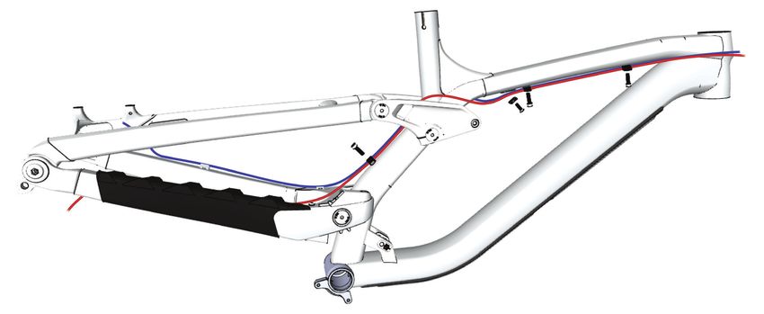
2022 Session Service Manual

Required adjustments for 27.5" wheels
The Session can accommodate:
     • 27.5" front and rear wheels
     • 29" front wheel and 27.5" rear wheel

When using 27.5" front and rear wheels an extended headset cup must be installed, and the rocker pivot Mino Link set to the
high position. See the Adjust the geometry section on page 6 for information about adjusting the Mino Link.

Install the extended headset cup

                                                               1

 Item        Description                                                                                      Part Number
     1      Extended headset cup                                                                              W5251089

Tools
          • Headset cup removal tool
          • Grease
1.        Use the headset cup removal tool to remove the
          existing cup.
2.            Apply grease to the lower head tube bearing
              bore.
3.        Press the extended headset cup into the headset.

                                                                                                                              2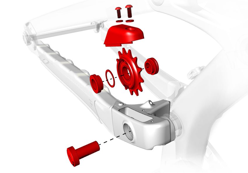
2022 Session Service Manual

Idler pulley
The idler pulley and spacers can be repositioned to align the idler pulley with the chainring. For instructions, refer to the
 Adjust the position of the idler pulley section on page 4.
                                                                3

                                                        2                   2
                                                                                     4

                                                        1
                                                    6                              5

                                            7

                                    8

  Item     Description                                                              Quantity in    Part Number       Torque (Nm)
                                                                                    Assembly
    1     Idler pulley                                                                  1          W1042533              —
    2     Washer                                                                        2          W5251170              —
    3     Idler guard bolts                                                             2          W1052364               1
    4     Idler guard                                                                   1          W1052385              —
    5     Spacer, black, grooved, 4.5mm                                                 1          W5251169              —
    6     Spacer, 0.5mm                                                                 1          W5265886              —
    7     Spacer, grey, 3.5mm                                                           1          W5251168              —
    8     Idler bolt                                                                    1          W1051961              17

                                                                                                                                   3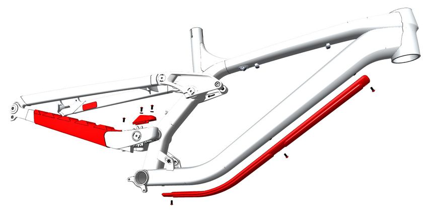
2022 Session Service Manual

Idler pulley (continued)
Typical idler pulley and chainring alignment
                      With a SRAM chainring                                           With a Shimano chainring

Adjust the position of the idler pulley
Different chainrings or slight tolerance differences in chainrings may require the idler pulley and spacers to be repositioned to
align the pulley with the chainring. To achieve alignment, do one or a combination of the following:

            Flip the idler pulley.              Position the 3.5mm and 4.5mm                    Position the 0.5mm spacer on
                                             spacers on either side of the idler pulley.        either side of the idler pulley.
Tools                                                                  5.         Apply grease to the shoulder of the idler bolt (8).
     • 6mm hex tool
     • Torque wrench with 6mm hex bit                                  6.    Place the assembled components into position in the
     • Grease                                                                chainstay.
1.     Inspect the current installation to determine the               7.    Install the idler bolt (8) from the drive side into the
       distance the idler pulley must be shifted to align with               frame.
       the chainring.                                                  8.    Torque the idler bolt (8) to 17Nm.
2.     Remove the idler bolt (8).
3.     Remove the idler pulley (1) and spacers (5, 6 and 7)
       from the chainstay.
4.     Reassemble the components, using the options
       shown in the three illustrations above, to shift the
       position of the idler.
        Notice: When repositioning the components, all
        spacers must be used in the final configuration.

                                                                                                                                       4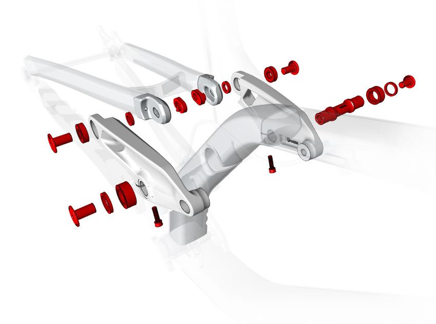
2022 Session Service Manual

Rocker pivot
                                                                              5
                                                                 7                               4
                                                                     6
                                                   6
                                       5

                                                                                                                  3
                                                                                                             2
                                                                                                     1
                              4

                                                           2
                                                       3                           8
 Item        Description                                                                   Quantity in     Part Number        Torque (Nm)
                                                                                           Assembly
     1      Rocker axle                                                                         1         W1042544                  —
     2      Bearing                                                                             2         W302025"                  —
     3      Spacer                                                                              2         W440921                   —
     4      Bolt                                                                                4         W1051959                  17
     5      Mino link bearing                                                                   2         W275322                   —
     6      Spacer                                                                              2         W529969                   —
     7      Mino Link bearing                                                                   2         W529223                   —
     8      Pinch bolt                                                                          2         W5256244                  5

Tools                                                                    9.       Install the bolt into the rocker plate. Tighten, but do
     • Bearing press                                                              not torque the bolt.
     • 4mm and 5mm hex wrenches                                          10. Repeat steps 1–9 on the other side.
     • Torque wrench with 4mm and 5mm hex bits
IMPORTANT: For proper alignment of the rocker plates,                    Mino Link chip
the shock must be installed and torqued, and the Mino                    1.       Press the Mino Link bearings (5) into the rocker
Link bolts installed and torqued, before the pinch bolts are                      plates.
torqued.
                                                                         2.       Position the seatstay between the rocker plates.
Rocker pivot                                                             3.       Position a spacer (6) between the seatstay tab and
                                                                                  the rocker plate. Repeat this step with the other spac-
1.        Press in the driveside bearing (2).                                     er on the other side.
2.             Apply grease to the shoulder of the drive side of                  Tip: Balance the spacer (6) against the bearing by
               the rocker axle (1).                                               partially inserting the bolt (4).
3.        Insert the rocker axle (1) into the frame from the non-        4.       Insert the Mino Link chips (7) into the notches on the
          drive side.                                                             seatstays.
4.             Apply grease to the shoulder of the non-drive             5.       Insert the bolts (4) into the Mino Link bearings (5) on
               side of the rocker axle (1).                                       the rocker plates.
5.        Install the non-driveside bearing (2) over the axle.           6.       Tighten, but do not torque the bolts (4).
          Press the bearing in from the non-drive side.
6.        Install a spacer (3) over the bearing.                         Pinch bolts
7.        Position the rocker plate so it aligns with the shoul-         1.       Install, but do not tighten the pinch bolts (8).
          ders of the axle.
                                                                         Torque all bolts
8.             Apply grease to the shoulder of the bolt (4).
                                                                         1.       Torque the bolts (4) to 17Nm.
                                                                         2.       Torque the pinch bolts (8) to 5Nm.
                                                                                                                                            5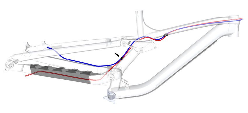
2022 Session Service Manual

Adjust the geometry
Flip the rocker pivot Mino Link chip to change the bike’s geometry to fit your riding style or the terrain. Flipping the Mino Link
chip from the high to the low position slackens the geometry by moving the head tube angle back 0.5° and lowering the bot-
tom bracket up to 9mm.

Mino Link high                                                     Mino Link low

       Position the chip with the Mino Link logo to the back            Position the chip with the Mino Link logo to the front

     • Creates a steeper head tube angle                             • Creates a slacker head tube angle
     • Pulls in the front fork for quicker steering                  • Pushes out the front fork for slower steering that is
     • Raises the bottom bracket for improved climbing                 more stable at high speed
                                                                     • Lowers the bottom bracket for more stability
Use this position when using 27.5" wheels or a 29" wheel
up front and a 27.5" wheel in the back.

Tools
     • 5mm hex tool
1.     With the bike on the ground, loosen and remove one Mino Link chip.
2.     Loosen and remove the other Mino Link chip.
3.     Position the bike:
       Mino Link high: Lift the bike by the seat tube. This
       will pull the rear triangle up and forward.
       Mino Link low: With the chips removed, gravity will
       pull the rear triangle down and back.
4.     Place one Mino Link chip into the desired position.
       Slightly tighten the Mino Link bolt.
5.     Install the other Mino Link chip into the same posi-
       tion. Slightly tighten the Mino Link bolt.
6.     Torque both Mino Link bolts to 17Nm.

                                                                                                                                     6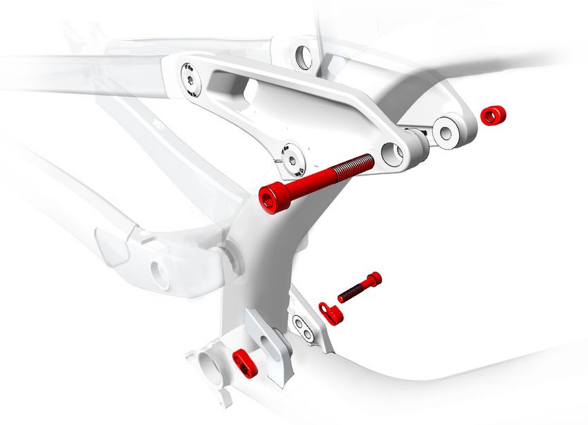
2022 Session Service Manual

Main pivot

                                                                                           1
                                                                                   2
                                                                               3
                                                                           4

                                                                       3
                                                                   2
                                                               5

 Item        Description                                                       Quantity in     Part Number   Torque (Nm)
                                                                               Assembly
     1      Axle                                                                      1       5256639            30
     2      Spacer                                                                    2       W440921            —
     3      Bearing                                                                   2       W302025"           —
     4      Sleeve                                                                    1       5256639            —
     5      Nut                                                                       1       W584134            —

Tools
     •    Bearing press
     •    8mm hex tool
     •    Torque wrench with 8mm hex bit
     •    Grease
1.        Press in the driveside bearing (3).
2.        Insert the sleeve (4) from the non-drive side.
3.        Press in the non-driveside bearing (3).

Tip: The sleeve and bearing must be properly aligned to
allow the axle to pass through. To aid in alignment, use the
bearing press to hold the sleeve in position while pressing
in the bearing.
4.        Install one spacer (2) over the non-driveside bearing (3).

5.             Apply grease to the shoulder of the axle (1).
6.        Insert the axle (1) from the non-drive side.
7.        Install the other spacer (2) over the driveside bearing.
8.        Install the nut (5).
9.        Torque the axle to 30Nm.

                                                                                                                           7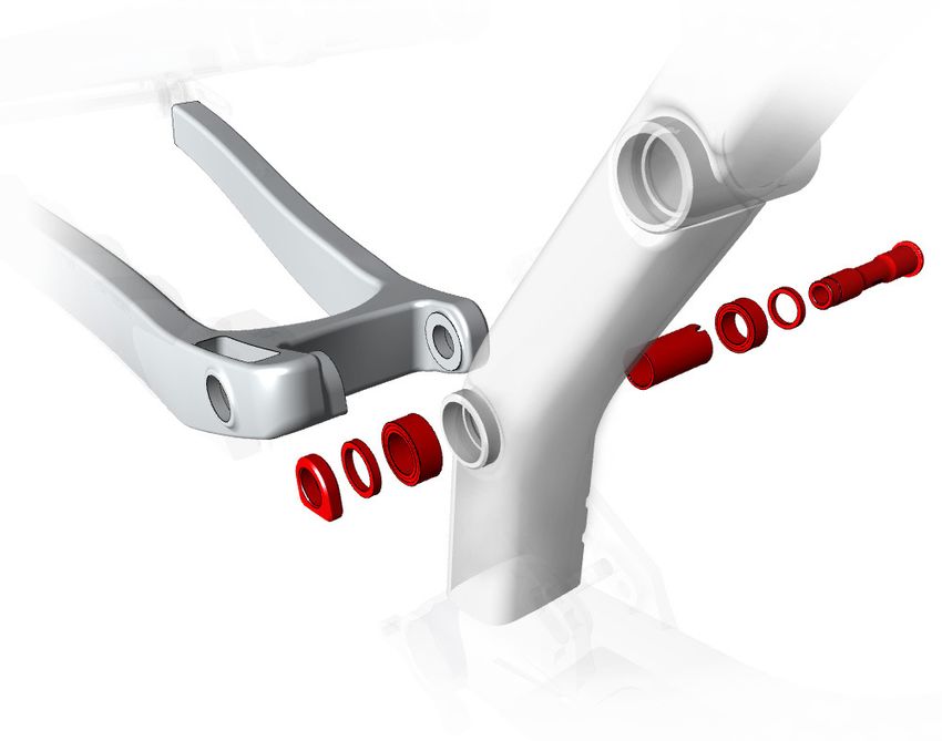
2022 Session Service Manual

Dérailleur hanger

                                                                                           2

                                                                                    1

 Item        Description                                                   Quantity in     Part Number      Torque (Nm)
                                                                           Assembly
     1      Dérailleur hanger                                                  1          W583423               —
     2      Hanger bolt, left-handed thread                                    1                                25
             Washer, 25mm                                                       1

Tools                                                          4.   Make sure the hanger is positioned as shown below.
     • 8mm hex tool
     • Torque wrench (left-hand thread) with 8mm hex bit

This bicycle frame is designed to use a Universal Derailleur
Hanger (UDH).
 NOTICE: The thru axle must be compatible with a UDH
 and must be M12x1.0 with a 12.7mm thread.
 NOTICE: The washer is frame-specific. Install only the
 washer compatible with your frame.
                                                               5.   Torque the hanger bolt to 25Nm.

             WARNING                                           NOTICE: Do not over-tighten. Over-tightening the bolt
                                                               could cause the hanger to break.
 Do not apply grease to the derailleur hanger or bolt.
 Apply grease to only the thru axle.
                                                               For additional information about the UDH, refer to the
                                                               SRAM user manual at www.sram.com.
1.        Insert the hanger on the inside of the driveside
          chainstay.
2.        Install the washer on the derailleur hanger bolt.
3.        Insert the bolt into the frame.

                                                                                                                          8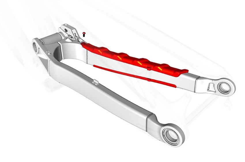
2022 Session Service Manual

Active Braking Pivot

                                                                                                                  4
                                                                     2   3    4            5
                                                       1

 Item        Description                                                          Quantity in   Part Number       Torque (Nm)
                                                                                  Assembly
     1      Thru axle                                                                 1        W598581               10
     2      Dropout axle                                                              1        W5251141              15
     3      Retaining ring                                                            1        W5251279               —
     4      Bearing                                                                   2        W583424                —
     5      Non-driveside dropout                                                     1        W583419                —

Tools
     •    Bearing press
     •    8mm hex tool
     •    Torque wrench (left-hand thread) with 8mm hex bit
     •    Cassette lockring
     •    Grease

1.        Press in the driveside bearing (4).                   8.            Apply grease to the threads of the thru axle (1),
2.        Press in the non-driveside bearing (4).                             and a lighter amount of grease to the shaft of
                                                                              the thru axle (1).
3.        Place the retaining ring (3) over the non-driveside
          bearing.                                              9.       Insert the thru axle into the dropout.
                                                                10. Torque the thru axle to 10Nm.
4.             Apply grease to the non-driveside dropout (5).
5.        Install the non-driveside dropout (5).

6.             Apply grease to the dropout axle (2).
7.        Insert the dropout axle (2) into the outside of the
          non-drive side.

                                                                                                                                  9
2022 Session Service Manual
Shock mounts
2
1
3
4
5
Item Description Quantity in Part Number Torque (Nm)
Assembly
1 Upper shock bolt 1 10
5272748
2 Nut 1 —
3 Lower shock bolt 1 10
4 Mino link spacer 1 5272749 —
5 Mino Link chip 1 —
102022 Session Service Manual
Adjust the progression
The shock Mino Link chip can be flipped to fine tune the shock performance for the terrain or rider preference.
20% progression (softer) 25% progression (firmer)
Position the Mino Link chip with 20% on top Position the Mino Link chip with 25% on top
• More reactive to repeated fast mid-size bumps and • More bottom out resistance over big hits and drops
square-edge hits
Tools
• 6mm hex tool
• Torque wrench with 6mm hex bit
1. Make sure the Mino Links on the rocker plates are in the low position.
For instructions, see the Adjust the geometry section on page 6.
2. Remove the lower shock bolt. For the location, see the Shock mounts section on page 10.
3. Flip the shock Mino Link chip to the desired position.
4. Re-install the lower shock bolt and torque to 10Nm.
112022 Session Service Manual
Frame guards
2
4
2
5
1
3 6
2
Item Description Quantity in Part Number Torque (Nm)
Assembly
1 Down tube guard 1 W1052375 —
2 Screw 6 W1052364 0.8
3 Chainstay guard 1 W1052384 —
4 Brake cable adhesive scuff guard 1 W326986 —
5 Idler pulley guard 1 W1052385 —
6 Washer 2 W5265886 —
Zip tie 1 — —
Brake cable scuff guard
Use isopropyl alcohol to clean the frame surface where
the guard (4) attaches. Wait for the alcohol to dry before
applying the guard.
Notice: Do not clean the entire frame with isopropyl
alcohol. Isopropyl alcohol could damage the paint.
122022 Session Service Manual
Cabling
The Session ships with cables routed internally, but includes options for routing cables externally for quick component
changes or repairs.
Internal cable routing
1
3
2
6
Optional external cable routing
3
1
3
2
5
2
6 4
Quantity in
Item Description Assembly Part Number Torque (Nm)
1 Rear brake cable 1 — —
2 Socket head cap screw 3 W5256244 3
3 Dual cable guide 3 W311726 —
4 Flat head bolt 1 W532763 3
5 Guide assembly 1 W502054 —
6 Derailleur cable 1 — —
Zip tie location 2 — —
132022 Session Service Manual
Specifications
Chainline (1x only) Seat post
WARNING
Always follow the seatpost manufacturer’s minimum
insertion recommendation. Failure to follow the recom-
55.5–58.5mm
mendation could cause damage to the seatpost and
result in injury to the rider.
3
Chainring (1x only) 2
Minimum 32T
1
Maximum 38T
Rear brake mount
Minimum 180mm, direct mount
Item Measurement
Maximum 220 mm
1 Maximum R1 frame 131 mm
insertion R2 frame 167 mm
Maximum tyre size R3 frame 170 mm
Notice: Measurements of actual tyres may vary. Always 2 Minimum insertion 75mm*
verify there is sufficient clearance between the tyre and 3 Diameter 31.6 mm
the frame. Improper tyre size could damage the bicycle *Follow the seatpost manufacturer guidelines.
frame. Trek recommends 6mm clearance above and on
the sides of the tyre.
Wheel set Maximum tyre size Bottom bracket
29" 29.0" x 2.60" • BSA83 threaded
27.5" 27.5" x 2.60"
Combination of 27.5” x 2.60”
29" and 27.5"
142022 Session Service Manual
Suspension
The first step in suspension setup is to determine the sag. All other settings should be adjusted after determining the sag.
Refer to the suspension setup card included with your bike or the suspension calculator at Trekbikes.com/suspension-calcula-
tor.
For recommended rebound settings refer to the suspension calculator at Trekbikes.com/suspension-calculator.
Fork Shock
Mount Width
WARNING Bottom mount 25 mm
Exceeding the recommended maximum fork length could Top mount 30 mm
damage the bicycle and result in injury to the rider.
3
2
1
1
3
2
Item Description Dimension
1 Eye-to-eye length 350 mm
2 Stroke length 72.5 mm
Item Description Dimension 3 Recommended sag 27–30%
1 Recommended sag 30 mm
2 Maximum travel 203 mm
3 Maximum length 29" wheels 602 mm
25.5" wheels 586 mm
with extended
headset cup
installed
15You can also read