4-Series Control Systems - Security Reference Guide Crestron Electronics, Inc.
←
→
Page content transcription
If your browser does not render page correctly, please read the page content below
4-Series™ Control Systems
       Security Reference Guide
                 Crestron Electronics, Inc.
Original Instructions The U.S. English version of this document is the original instructions. All other languages are a translation of the original instructions. Crestron product development software is licensed to Crestron dealers and Crestron Service Providers (CSPs) under a limited nonexclusive, nontransferable Software Development Tools License Agreement. Crestron product operating system software is licensed to Crestron dealers, CSPs, and end-users under a separate End-User License Agreement. Both of these Agreements can be found on the Crestron website at www.crestron.com/legal/software_license_ agreement. The product warranty can be found at www.crestron.com/warranty. The specific patents that cover Crestron products are listed at www.crestron.com/legal/patents. Certain Crestron products contain open source software. For specific information, visit www.crestron.com/opensource. Crestron, the Crestron logo, 4-Series, infiNET EX, and SmartObjects are either trademarks or registered trademarks of Crestron Electronics, Inc. in the United States and/or other countries. Linux is either a trademark or a registered trademark of Linus Torvalds in the United States and/or other countries. Active Directory and Windows are either trademarks or registered trademarks of Microsoft Corporation in the United States and/or other countries. Other trademarks, registered trademarks, and trade names may be used in this document to refer to either the entities claiming the marks and names or their products. Crestron disclaims any proprietary interest in the marks and names of others. Crestron is not responsible for errors in typography or photography. ©2022 Crestron Electronics, Inc.
Revision History
 Rev        Date                   Notes                                              Author(s)

 A          July 8, 2021           Initial version                                    IH

 B          January 7, 2022        Incorporated major updates from Military Unique    IH, JD
                                   version of document

Please send comments and change recommendations to:

SecurityDocs@crestron.com

Security Reference Guide — Doc. 9063B                                          4-Series™ Control Systems • i
ii • Contents Security Reference Guide — Doc. 9063B
Contents
   Overview                                                 1

   Ports and Protocols                                     2

   Prerequisites                                           4
     Operating Environment                                 4
     Firmware Version                                      4
     Device Access                                         4
     Default Configuration Settings                        5

   Required Configuration                                  6
     Configure the Network                                 6
        DHCP or Static IP Address Configuration            6
        802.1X Authentication                              6
     Set Password Policy                                  10
     Set Date and Time                                    10
     Control Subnet                                       12
        Control Subnet Architecture                       13
        Control Subnet Configuration                      14
     Disable Auto Discovery                               16
     Disable Cloud Features                               16
     Disable Wireless Communications                      16
     Enable User Account Locking                          17
        Change Login Failure Count                        17
        Change Lockout Time                               17
     Display Last Logged-In Information                   17
     Enable Session Inactivity Timeout                    18
     Enable Audit Logging                                 18
     Initial Login Process                                19
     Enable All Certificate Verifications                 19
     Load Default Server Certificates                     19

   Optional Configuration                                20
     Enable or Disable Web Server                        20
     Enable User Login IP Blocking                       20
       Change Login IP Failure Count                     20
       Change IP Blocked Time                            20
     Configure SNMP                                       21
       Add or Remove an SNMP Manager                      21
       Enable or Disable Unrestricted SNMP Access        22
       Configure SNMP Access Information                 22

Security Reference Guide — Doc. 9063B               Contents • iii
Enable or Disable SNMP Notifications 23
Add Users and Groups 23
Enable Sending Audit Logs to Remote Syslog Server 23
Secure Control System Connection 24
Management Functions 25
Firmware Update 25
User and Group Management 25
Add Local User 25
Delete Local User 25
Add Local Group 26
Delete Local Group 26
List Local Groups 26
Add Active Directory Group 27
Remove Active Directory Group 27
List Active Directory Groups 28
List Users 28
List Group Users 28
Show User Information 28
Add User to Group 29
Remove User from Group 29
Update Local Password 29
Reset User Password 29
User Login IP Blocking Management 30
List Blocked IP Addresses 30
Add IP Address to Blocked List 30
Remove IP Address from Blocked List 30
User Account Locking Management 31
Add User to Locked List 31
Remove User from Locked List 31
List Locked User 31
Certificate Management 32
Certificate Requirements 33
Certificate Commands 33
Default Server Certificate 36
Additional Instructions 39
Use OpenSSL to Create a Certificate Signing Request (CSR) 39
Create a Configuration File 39
Generate the Private Key 41
Create the CSR 41
Create and Sign the Certificate 41
Load the Certificate 42
Clean Up 42
iv • Contents Security Reference Guide — Doc. 9063BOverview This document describes the steps needed to harden a Crestron® installation with 4-Series™ control systems and assumes a basic understanding of security functions and protocols. This guide provides information about the system configuration used for 4-Series control systems firmware release 2.7000.00014 or later. NOTE: The term "device" is used in this document to refer to all applicable 4-Series control system models unless specified otherwise. The information in this guide pertains to the following device models: Model Description AV4 4-Series™ Control System CP4 4-Series™ Control System CP4N 4-Series™ Control System DIN-AP4 4-Series™ DIN Rail Control System MC4 4-Series™ Control System MC4-I 4-Series™ Control System, International PRO4 4-Series™ Control System RMC4 4-Series™ Control System Security Reference Guide — Doc. 9063B 4-Series™ Control Systems • 1
Ports and Protocols
The following ports and protocols may be used by the device depending on the system design
and configuration.
Crestron Control Devices

 Function          Destination Port    From (Sender)    To (Listener)       Notes

 Crestron-         41794/TCP           Remote           Device              Crestron Internet Protocol
 CIP                                   Device

 Crestron-         41796/TCP           Remote           Device              Secure Crestron Internet
 SCIP                                  Device                               Protocol

 HTTPS             49200/TCP           Remote           Device              Web API for Crestron HTML5
                                       Device                               User Interfaces

Common Ports

 Function           Destination Port    From (Sender)       To (Listener)        Notes

 NTP                123/UDP             Device              NTP Server           Network Time Protocol
                                                                                 (NTP)

 SSH/SFTP           22/TCP              Admin               Device               Used for configuration,
                                        Workstation                              console, and file transfer

 LDAP               3268/TCP            Device              LDAP Server          LDAP queries targeting
                                                                                 global catalogs

 HTTPS              443/TCP             Admin or End        Device               Secure web configuration
                                        User
                                        Workstation

 HTTPS              443/TCP             Device              XiO Cloud®           For XiO Cloud services only
                                                            Service              and not required for device
                                                                                 functionality. A persistent
                                                                                 connection is made via
                                                                                 AMQP over WebSockets.
                                                                                 HTTPS services such as
                                                                                 routing lookups and file
                                                                                 transfers may be used.

 DHCP               67/UDP              Device              DHCP Server          DHCP addressing

 DHCP               68/UDP              DHCP Server         Device               DHCP addressing

 HTTP               80/TCP              End User            Device               Redirect to Secure Web
                                        Workstation                              Configuration on port 443

 Remote             Configurable        Device              Remote               Uses TLS
 Syslog                                                     Syslog Server

2 • 4-Series™ Control Systems                                               Security Reference Guide — Doc. 9063B
Function Destination Port From (Sender) To (Listener) Notes
SNMP 161/UDP SNMP Manager Device
SNMP Traps 162/UDP Device SNMP
Manager
Security Reference Guide — Doc. 9063B 4-Series™ Control Systems • 3Prerequisites
In order to perform a secure configuration, the following prerequisites must be met.
Operating Environment
Crestron assumes the following about the operating environment of its systems:
l The system is not capable of Multi-Factor Authentication (MFA). If your organization's
policy requires MFA, you cannot use the system.
l Physical security is commensurate with the value of the system and the data it contains
and is assumed to be provided by the environment.
l Administrators are trusted to follow and provide all administrator guidance.
Firmware Version
4-Series control systems must be running firmware version 2.7000.00014 or later.
Device Access
The administrator can access and configure the device by using a web browser or an SSH client.
This document describes device configuration using an SSH client, which provides access to
console commands. Some configuration capabilities can only be performed by issuing console
commands. Additionally, some aspects of configuration can be performed via Crestron Toolbox™
software, or the XiO Cloud® service.
NOTE: The SSH client that is used must be capable of connecting to the device using SSHv2
and must be compatible with FIPS 140-2 validated algorithms.
As an alternative to using an SSH client, the same console commands can be executed through
the USB port.
4 • 4-Series™ Control Systems Security Reference Guide — Doc. 9063BDefault Configuration Settings
In order to configure the device, it must first be placed in its factory default state. A device can
be returned to this state by entering the following command on the console:
RESTORE
If you do not have access to the console (for example, the password has been lost), a factory
reset may be performed as follows:
1. Press and release the HW-R button on the front panel of the control system.
2. Quickly press the SW-R button on the front panel of the control system 5 times, with less
than a one-second gap between each press.
3. Wait 5 to 10 minutes for the self-recovery process to complete.
4. Proceed with the network configuration.
Security Reference Guide — Doc. 9063B 4-Series™ Control Systems • 5Required Configuration The following sections describe the configuration changes required for the device for a secure deployment. Configure the Network The following sections provide information about the tasks necessary to configure the network. DHCP or Static IP Address Configuration To configure the device to communicate on the local LAN, the following changes must be made. If DHCP is available on the local network, then no additional configuration changes are necessary. If DHCP is not available or if the administrator wishes to manually set the network configuration, then the IP address, IP mask, default gateway, and DNS server settings must be set. dhcp 0 off Turns off DHCP so that the manually configured network information is used. ipaddress 0 192.168.1.2 Sets the IP address of the device to the specified address. ipmask 0 255.255.255.0 Sets the IP mask of the device to the specified mask. defrouter 0 192.168.1.1 Sets the default network gateway to the specified IP address. adddns 192.168.1.10 Sets the DNS server to use for DNS name lookups. 802.1X Authentication 802.1X is an IEEE network standard designed to enhance the security of both wireless and wired Ethernet networks. This device supports 802.1X on its primary wired Ethernet interface only. If the network requires 802.1X, the device must be configured for 802.1X before being put on the network. This configuration can be done through the USB port console or by attaching it to a temporary network which does not require 802.1X. 6 • 4-Series™ Control Systems Security Reference Guide — Doc. 9063B
Before configuring 802.1X, perform the following tasks as necessary:
    l   Unless server authentication is going to be disabled, the trusted x.509 certificate or
        certificates that will be used to verify the 802.1X server’s certificate must be loaded into
        the device. Use the certificate management commands to load the trusted certificates
        into the device. These may be Root or Intermediate certificates. Refer to the Certificate
        Management (on page 32) section for instructions.
    l   If EAP-TLS authentication is going to be used, a client certificate will be needed and must
        be loaded into the device. Refer to the Certificate Management (on page 32) section for
        instructions to load a client certificate into the “machine” store.

Once 802.1X configuration is complete, reboot the device to activate those settings. The device
will try to connect to the 802.1X network when it starts up.

802.1X Configuration
In order to configure and use 802.1X, various aspects of 802.1X will need to be configured,
including enabling it, setting up server authentication, and selecting a client authentication
method. The following commands are used for this configuration:

Enable 802.1X
To enable 802.1X, issue the following command:

8021xauthenticate [on/off]
    l   on - 802.1X is enabled
    l   off - 802.1X is disabled
    l   No parameter - Displays the current setting

Example: 8021xauthenticate on

Set Trusted Server Certificates
Unless server validation will be disabled, the trusted certificates that 802.1X will use to verify the
server’s certificate must be indicated. The full list of trusted Root and Intermediate certificates
loaded into the device is not used for 802.1X—only the specific certificates selected by the
8021xtrustedcas command are used. As indicated earlier, the trusted certificates must first be
loaded into the device using the standard Certificate Management commands.

The following commands can be used to list, add, and remove certificates from the list of
certificates that will be used by 802.1X.

Security Reference Guide — Doc. 9063B                                        4-Series™ Control Systems • 7
List Certificates
To list available certificates, issue the following command:
8021xtrustedcas [list|listn|listu]
l list - Shows all Root and Intermediate certificates for the device
l listn - Shows all Root and Intermediate certificates for the device and also includes
identification number of each certificate
l listu - Shows Root and Intermediate certificates that are used by 802.1X
Example: 8021xtrustedcas listn
This certificate list will show the name and UID of each certificate, along with an indication of
whether or not it is being used by 802.1X.
Add Certificate to 802.1X Trust List
To add a certificate to the list of trusted certificates to be used by 802.1X, issue the following
command:
8021xtrustedcas use [certificate number] [certificate name] [certificate UID]
l certificate number - Number that identifies the specific certificate to use
l certificate name - Name that identifies the specific certificate to use
l certificate UID - UID that identifies the specific certificate to use
Only one identifier (number, name, or UID) is needed. These identifiers can be determined by
listing the certificates using the 8021xtrustedcas list or 8021xtrustedcas listn described
above. Only the listn command will show the certificate number.
Remove Certificate from 802.1X Trust List
To remove a certificate from the list of trusted certificates to be used by 802.1X, issue the
following command:
8021xtrustedcas dontuse [certificate number] [certificate name] [certificate
UID]
l certificate number - Number that identifies the specific certificate to remove
l certificate name - Name that identifies the specific certificate to remove
l certificate UID - UID that identifies the specific certificate to remove
Only one identifier (number, name, or UID) is needed. These identifiers can be determined by
listing the certificates using the 8021xtrustedcas list or 8021xtrustedcas listn described
above. Only the listn command will show the certificate number.
Removing a certificate from 802.1X does not remove the certificate from the device. The
certificate will still be present in the Root or Intermediate store.
8 • 4-Series™ Control Systems Security Reference Guide — Doc. 9063BEnable 802.1X Server Validation
Under most circumstances, validation of the 802.1X server should be enabled. By default, server
validation is disabled on this device.
To enable 802.1X server validation, issue the following command:
8021xvalidateserver [off | on]
l off - 802.1X supplicant will not validate authentication server's certificate.
l on - 802.1X supplicant will validate authentication server's certificate.
l No parameter - Displays the current setting
Example: 8021xvalidateserver on
Select 802.1X Client Authentication Method
802.1X requires that the device authenticate with the server before it will be allowed on the
network. The device supports two client authentications methods: PEAPv0/EAP-MSCHAPv2 and
EAP-TLS. PEAPv0/EAP-MSCHAPv2 requires a user name and password, and EAP-TLS requires a
client certificate.
To select the 802.1X client authentication method, issue the following command:
8021xmethod [password/certificate]
l password - Uses PEAPv0/EAP-MSCHAPv2 authentication
l certificate - Uses EAP-TLS authentication
Example: 8021xmethod password
If EAP-TLS is selected, a client certificate must be loaded into the device as explained earlier in
the 802.1X instructions.
If PEAPv0/EAP-MSCHAPv2 is selected, the user name and password to use for authentication
must be entered with the following commands:
8021xusername [username]
8021xpassword [password]
Additional 802.1X Options
Additional 802.1X options may need to be configured if required by the network to which the
device is connected:
l If the 802.1X server requires that a specific domain name be included with the 802.1X
authentication request, the domain name can be set by issuing the following command:
8021xdomain [domain_name]
l If using PEAPv0/EAP-MSCHAPv2 authentication and the server requires the PEAP version
to be sent as part of the authentication request, the PEAP version can be enabled with the
on option in the following command:
8021xsendpeapver [on/off]
Security Reference Guide — Doc. 9063B 4-Series™ Control Systems • 9Set Password Policy
To set the password policy, issue the following command:
setpasswordrule{-all|-none}|{-length:minpasswordlength}{-mixed}{-digit}{-
special}
l -all - All password rules are applied.
l -none - No password rules are applied.
l -length: - Specifies the minimum password length. By default, the minimum password
length is six characters.
l -mixed - Specifies that the password must contain a lower and upper case character.
l -digit - Specifies that the password must contain a numeric character.
l -special - Specifies that the password must contain a special character.
NOTE: The -length, -mixed, -digit, and -special parameters cannot be combined with -
none.
Example: setpasswordrule -length:9 -mixed -digit -special
NOTE: The following special characters are permitted: ` ~ ! @ $ % ^ & * ( ) _ + = { } [ ] | ; " < > , .
All passwords that are created, updated, or reset for local users must follow the password rules
set by this command to be considered valid.
As a security best practice, Crestron recommends setting the password policy to the following:
setpasswordrule -length:15 -all
Set Date and Time
All devices use NTP to synchronize their clock. To disable NTP synchronization and set the current
date and time manually, issue the following commands:
sntp stop
timedate hh:mm:ss mm-dd-yyyy
NOTE: Enter the current time (24-hour clock format, including minutes and seconds) and date.
By default, the time zone is set to EST (code 014). This is never changed automatically and must
be changed manually if desired. To set the time zone, issue the following command:
timezone [list | zone]
l list - Returns a list of all time zones and codes
l zone - Enter the code of the time zone to be used
Example: timezone 005
10 • 4-Series™ Control Systems Security Reference Guide — Doc. 9063BBy default, NTP is enabled and is configured to get the time from pool.ntp.org. The device
supports using up to three NTP servers, including authentication servers. Issue the following
command to configure custom NTP servers for time synchronization:
sntp[start|stop|sync|delete{server|server2|server3}|server{args}|server2
{args}|server3{args}]
l start - Starts synchronization
l stop - Stops synchronization
l sync - Forces synchronization one time
l delete {server|server2|server3} - Deletes configuration for NTP server1, server2, or
server3
l server:{address} [optional args] - Address of primary NTP server with optional
arguments
l server2:{address} [optional args] - Address of secondary NTP server to
synchronize with optional arguments
l server3:{address} [optional args] - Address of secondary NTP server to
synchronize with optional arguments
l optional args:
o port:{1-65535} - NTP port (default 123)
o auth:{mac} - Secured NTP MAC authentication
o keytype:{md5(less secured)|sha1|sha256} - Key type for MAC authentication
only (default sha1)
NOTE: md5 is not allowed when FIPSMODE is on.
o key:{shared key} - Pre-shared key between NTP client and server (MAC
authentication only)
o keyid:{1-65535} - Pre-shared key index between NTP client and server (MAC
authentication only)
l No parameter - Displays the current settings
Example: SNTP SERVER:macntp.example.com AUTH:mac KEYID:1
KEY:e5fa44f2b31c1fb553b6021e7360d07d5d91ff5e
NOTE: NTP servers are configured into a particular slot. The server configured into the
SERVER slot will be the primary server used for time synchronization. The servers configured
into the SERVER2 and SERVER3 slots will be used as secondary servers.
Security Reference Guide — Doc. 9063B 4-Series™ Control Systems • 11Control Subnet
Certain 4-Series control system models provide support for a separate network called a Control
Subnet and have one or more network ports specifically for connecting devices to the Control
Subnet. If your device has a Control Subnet, it must be configured.
The Crestron AV4, CP4N, and PRO4 have a dedicated Control Subnet, which allows for dedicated
communication between the control system and Crestron Ethernet devices without interference
from other network traffic on the LAN. The AV4 and PRO4 provide four Control Subnet ports
that also support PoE+ using the optional PW-5430DUS power supply.
CAUTION: Do not connect the CONTROL SUBNET port to the LAN. The CONTROL SUBNET
port must only be connected to Crestron Ethernet devices.
When using the Control Subnet, observe the following:
l The control system acts as a DHCP server to all devices connected to the Control Subnet
and assigns IP addresses as needed.
l A DNS server is built in to the control system to resolve host names.
l Only connect Crestron Ethernet devices to the Control Subnet.
l The control system operates in isolation mode by issuing the isolatenetworks on
command. When in isolation mode, the firewall is configured so that no communication
can occur between the LAN and devices on the Control Subnet. Using this mechanism,
customers can protect their corporate LAN from devices on the Control Subnet.
l When in isolation mode, devices on the Control Subnet do not have any resources on the
LAN side. For example, if a touch screen with a SmartObjects® technology object requiring
network access is installed on the Control Subnet, the object will not work.
l Devices on the LAN do not have access to any devices on the Control Subnet. Crestron
Toolbox also does not have access to these devices when it is connected to the LAN. To
configure devices on the Control Subnet with Crestron Toolbox (outside of runtime), the
computer running Crestron Toolbox must be connected to the Control Subnet.
l Any NAT/port mapping rules that were previously created do not work when the control
system is in isolation mode.
NOTE: If the control system is running in isolation mode, Crestron Ethernet devices requiring
internet access should not be connected to the CONTROL SUBNET port (directly or indirectly)
and should be instead connected to the LAN.
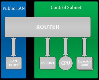
12 • 4-Series™ Control Systems Security Reference Guide — Doc. 9063BControl Subnet Architecture
Even if nothing is plugged into the CONTROL SUBNET port(s) on the back on the control system,
the following are still present on the Control Subnet:
l Control System CPU (where AV programs run)
l Optional Expansion cards (PRO4 and AV4 only)
This design is in place to ensure that the Crestron CPU and optional expansion cards are
protected from malicious packets on the LAN. Refer to the diagram below for more information
on how these components work together.
Public LAN/Control Subnet Diagram
The firewall rules permit entry to only the traffic that is listened to by the CPU. As a result, a port
scan will only show ports that are listened to by the CPU. Users can set up manual port
forwarding rules to make custom connections to the devices on the Control Subnet.
Security Reference Guide — Doc. 9063B 4-Series™ Control Systems • 13Control Subnet Configuration
For increased security, the device supports a mode of operation called isolation mode. In
isolation mode, the firewall is preconfigured to limit access to the Control Subnet, port mapping
between the primary network and devices on the Control Subnet are blocked, and manual
configuration of port forwarding is not available. To configure isolation mode, issue the following
command:
isolatenetworks [state]
l state - {ON | OFF}
l No parameter - Displays the current setting
Example: isolatenetworks on
As a security best practice, the device should have its Control Subnet in isolation mode.
Control Subnet Router Configuration
By default, the Control Subnet router is configured to use 10.0.0.0/8 for the Control Subnet. If
the device detects that the primary network is using that network address, the device will
automatically switch to using 172.22.0.0/16 for the Control Subnet. To verify if the device is
automatically choosing the Control Subnet address, issue the CSINAutoMode command. To
confirm what address is being used, issue the ipconfig command to show the addresses
assigned to the device’s network interfaces.
If the control system will use a specific network address, that address can be configured using
the following command:
CSRouterPrefix [IP_Address/Prefix_Size]
l IP_Address - The desired IP address
l Prefix_Size - The number of leading bits of the routing prefix
l No parameter - Displays the current Control Subnet configuration
Example: CSRouterPrefix 192.168.0.0/24
Control Subnet DHCP Configuration
By default, the device provides a DHCP server on the Control Subnet to issue IP addresses for
anything connected to the Control Subnet. IP addresses that have been issued can be displayed
by using the DHCPLeases command.
The DHCPLeases command will return a list of IP address that have been issued and information
about them.
In addition, specific IP addresses can be assigned to specific devices on the Control Subnet. This
can be done by issuing the following command:
RESERVEDLeases [ADD | REM | CLEAR_ALL]
14 • 4-Series™ Control Systems Security Reference Guide — Doc. 9063Bl ADD - Adds an IP address to a device using the following syntax: MAC_Address IP_
Address Description
o MAC_Address - The device MAC address
o IP_Address - The device IP address
o Description - A description of the device
l REM - Removes a previously created IP address from the device using the following
syntax: MAC_Address
o MAC_Address - The device MAC address
l CLEAR_ALL - Clears all previous created IP addresses
l No parameter - Displays all current reserved DHCP leases in table format
Example: RESERVEDLeases ADD 81:51:CA:48:73:24 10.0.0.9 TestDevice
The MAC address should be in the format XX:XX:XX:XX:XX:XX on the command line.
Control Subnet Firewall Configuration
In isolation mode, the firewall is preconfigured to limit access to the Control Subnet and cannot
be further configured. The firewall configuration in isolation Mode is as follows:
Control System Firewall Rules - Isolation Mode
Direction Port(s) Rule Description
Inbound from 22 To CPU SSH
LAN
Inbound from 80, 443 To CPU Web server (if enabled)
LAN
Inbound from 41794, 41796 To CPU Crestron communication protocols
LAN
Inbound from Listen ports To CPU Programmatic listeners
LAN used by
program
Inbound from 49200 To CPU Crestron HTML5 User Interface
LAN
Inbound from 64000–64299 Blocked In isolation mode, Crestron management tools
LAN cannot connect to any devices on the Control
Subnet
Control Subnet Any port All other No outbound traffic is allowed
Outbound to devices:
LAN Blocked
Inbound from User defined Blocked In isolation mode, no port forwarding can be
LAN managed by the user
Security Reference Guide — Doc. 9063B 4-Series™ Control Systems • 15Disable Auto Discovery All devices support an autodiscovery feature which allows them to be detected, report basic information, and do some basic configuration remotely. This feature is not protected by any type of authentication. Disable auto discovery with the following command: autodiscovery off Disable Cloud Features All devices connect to cloud services for remote monitoring and management. If your environment or policies do not permit communications with external services, disable cloud features by entering the following commands: enablefeature cloudclient off hydrogenenable off Disable Wireless Communications Certain control system models support infiNET EX® wireless communications. As a security best practice, this support should be disabled by issuing the following command: rfgateway off 16 • 4-Series™ Control Systems Security Reference Guide — Doc. 9063B
Enable User Account Locking
To prevent brute force attacks against a user's password, the device has the ability to
automatically lock an account after a number of failed login attempts. Note that this
functionality operates independently and simultaneously with the User Login IP Blocking
capability of the device.

NOTE: Access to an account over the USB port is never blocked.

Change Login Failure Count
To change the value for the login failure count, issue the following command:

setuserloginattempts [number]
    l   number - Number of login attempts a user can have before the console is blocked. A value
        of 0 indicates an infinite number of login attempts. A value of -1 restores the default
        value.
    l   No parameter - Displays the current setting

Example: setuserloginattempts 3

As a security best practice, the failure count should be set to 3.

Change Lockout Time
To change the duration that an IP address is blocked by the console, issue the following
command:

setuserlockouttime [number]
    l   number - Number of hours (suffix h) or minutes (suffix m) to block a user. A value of 0
        specifies an indefinite amount of time. The maximum amount of time is 750h (hours) or
        45000m (minutes). A value of -1 restores the default value.
    l   No parameter - Displays the current setting

Example: setuserlockouttime 15m

As a security best practice, the lockout time should be set to 15m.

Display Last Logged-In Information
Devices ido not display information about a user's last login or failed login attempts by default.
To have this information displayed, issue the following command:

showlogininfo on

Security Reference Guide — Doc. 9063B                                    4-Series™ Control Systems • 17
Enable Session Inactivity Timeout
NOTE: The Enable Session Inactivity Timeout command affects both console and web sessions.
Devices do not terminate a user session due to inactivity by default. Configure the device to
terminate inactive user sessions by issuing the following command:
setlogoffidletime 10
The number set with the setlogoffidletime command is the number of minutes after which
the session will be terminated. The number can range from 1 to 9999.
Enable Audit Logging
All devices have limited audit logging. Audit logging is turned off by default.
To configure audit logging, issue the following command:
auditlogging[on|off]{[all]|[none]|{[admin][prog][oper][user]}[remotesyslog]}
l on - Enables audit logging
l -off - Disables audit logging
l No parameter - Displays the current audit logging setting
l The following parameters are optional and are used to log commands by access level:
o admin - Logs administrator-level commands
o prog - Logs programmer-level commands
o oper - Logs operator-level commands
o user - Logs user-level commands
o all - Logs all commands
o none - Logs no commands
l remotesyslog - Writes to the remote syslog server only
Example: auditlogging on admin oper
Sample Log Output: [2021-11-30T07:02:44-08:00]: EVENT: COMMAND(SHELL
172.30.255.255) USER: admin # AUDITLogging on all
As a security best practice, full audit logging should be turned on by entering the following
command:
auditlogging on all
18 • 4-Series™ Control Systems Security Reference Guide — Doc. 9063BInitial Login Process A user name and password account must be created when the device is accessed for the first time. Using an SSH client, log in by entering Crestron and a blank password. To create the account, enter the desired user name and password (the password must be a minimum of 8 characters). Confirm the password by entering the password again. After the account is created, enter the user name and password to log in to the device. NOTE: Do not lose this information. The system cannot be accessed without it. Enable All Certificate Verifications By default, outgoing TLS connections for some protocols will not perform a full set of verifications on the server certificate if it is presented. Enable these verifications by issuing the following command: sslverify all Load Default Server Certificates The device requires a default server certificate for proper web server operation and to properly secure incoming CIP communications from other devices. Refer to the Certificate Management (on page 32) section for instructions to load the default server certificate and any other needed certificates. Security Reference Guide — Doc. 9063B 4-Series™ Control Systems • 19
Optional Configuration
The following sections provide information about optional device configuration settings.

Enable or Disable Web Server
All devices have an active web server. If desired, disable the web server with the following
command:
webserver off
To enable the web server, issue the following command:
webserver on

Enable User Login IP Blocking
To prevent distributed brute force attacks against user logins, the device has the ability to
automatically block an IP address after a number of failed login attempts from that IP address.
Note that this functionality operates independently and simultaneously with the User Account
Locking capability of the device.

NOTE: Access to an account over the USB port is never blocked.

Change Login IP Failure Count
To change the value for the logon failure count, issue the following command:

setloginattempts [number]
    l   number - Number of login attempts allowed before the console is blocked. A value of 0
        enables unlimited attempts. The default value is 3.
    l   No parameter - Displays the current setting

Example: setloginattempts 3

Change IP Blocked Time
To change the duration of time that an IP address is blocked by the console, issue the following
command:

setlockouttime [number]
    l   number - Number of hours to block an IP address. A value of 0 blocks the IP address
        indefinitely. The maximum value is 255. The default value is 24.
    l   No parameter - Displays the current setting

Example: setlockouttime 24

20 • 4-Series™ Control Systems                                     Security Reference Guide — Doc. 9063B
Configure SNMP
The device supports SNMP v2x and v3. To configure an SNMP Manager to access SNMP on this
device, it must be added with the SNMPMANager command and given access with the SNMPAccess
command. When using SNMP v3, the SNMP Manager must support EngineID Discovery (RFC
5343) since there is no current way to display the EngineID being used by the device.
Enable or Disable SNMP
To enable or disable SNMP, issue the following command:
snmp [enable | disable | wipe]
l enable - Enables SNMP
l disable - Disables SNMP
l wipe - Clears the configuration and disables SNMP
l No parameter - Displays the current setting
Example: snmp enable
Add or Remove an SNMP Manager
Add information about an SNMP Manager that will be accessing the device or receiving
notifications from the device. Note that this must be done even if the Manager will not be
receiving notifications from the device. The Manager can be removed when no longer in use.
To add or remove an SNMP Manager, issue the following command:
snmpmanager [add/remove] [name] [community name] [address] [params]
l params - Specifies one of the following:
noauthnopriv-v1
noauthnopriv-v2
noauthnopriv-v3
authnopriv-v3
authpriv-v3
o auth = authentication
o priv = privacy
Examples:
snmpmanager add testsitemanager testsitename 192.168.0.255 authpriv-v3
snmpmanager remove testsitemanager
For SNMPv2, the community name parameter is the SNMP community string. For SNMPv3, the
community name parameter is used as the SNMPv3 user name. Entering the command with no
parameters will list all the SNMP Managers that have been added.
As a security best practice, authpriv-v3 (full SNMPv3) should be used.
Security Reference Guide — Doc. 9063B 4-Series™ Control Systems • 21Enable or Disable Unrestricted SNMP Access
By default, SNMP managers sending requests with a community string as the only
authentication must send those requests from the IP address indicated when the manager was
defined with the SNMPMANager command. The following command can be used to remove that
restriction by changing the setting to on:
snmpallowall [on/off]
l on - Allows all managers
l off - Allows only permitted managers
l No parameter- displays current setting
By default, the command is set to off.
SNMPv3 requests are not affected by this command. SNMPv3 security is used to control access
and does not check IP addresses.
Configure SNMP Access Information
This enables SNMP requests and provides the needed information for an SNMP Manager that
has been created with the SNMPMANager command.
snmpaccess [community] [param] [-a:securitytype -p:password [-e:privacytype [-
k:key] ] ]
l param = readonlyaccess, readwriteaccess, noaccess
l securitytype = MD5, SHA
l privacytype = DES, AES
The -a and -p options are required if the SNMP Manager was configured with authnopriv-
v3,authpriv-v3.
The -e and -k options are required if the SNMP Manager was configured with authpriv-v3.
The string passed to the -p and -k options must be at least 8 characters long.
The MD5 authentication type and DES privacy types are not available when the device is in FIPS
140-2 operation.
Example: testsitename readwriteaccess -a:sha -p:secretstring1 -e:aes -
k:secretstring2
22 • 4-Series™ Control Systems Security Reference Guide — Doc. 9063BEnable or Disable SNMP Notifications
Notifications will be sent to all SNMP Managers that have been configured via the SNMPMANager
and SNMPAccess commands. The device currently supports TRAP notifications and does not
support INFORM notifications.
To enable or disable SNMP notifications, issue the following command:
snmptrap [on|off]
l on - Enables traps
l off - Disables traps
l No parameter- Displays the current setting
Example: snmptrap on
Add Users and Groups
It is likely that additional users—either local or via Active Directory® credential management—will
need to be given access to the device. Refer to the User and Group Management (on page 25)
section for instructions.
Enable Sending Audit Logs to Remote
Syslog Server
Devices do not send audit logs to a remote Syslog server by default. To enable sending to a
remote Syslog server, issue the following command:
remotesyslog [-s:] {-e:} {-a} [-i:address] [-p:port] {-t:protocol} {-v:on|off}
l -s:on|off enables or disables remote system error logging
l -e:ok|info|notice|warning|error|fatal decides which types of errors are logged.
Selecting a tier results in logging errors of that level of importance and above in a
hierarchy from ok to fatal.
o ok - Logs all "OK" errors and above to Syslog
o info - Logs all "info" errors and above to Syslog
o notice - Logs all "notice" errors and above to Syslog (default)
o warning - Logs all "warning" errors and above to Syslog
o error - Logs all "error" errors and above to Syslog
o FATAL - Logs all "fatal" errors and above to Syslog
Security Reference Guide — Doc. 9063B 4-Series™ Control Systems • 23l -a log
o Accesses Syslog contents of the audit log if remote system error logging is enabled
l -i:address
o Replaces address with the remote Syslog server IP address in dot decimal notation
or an ASCII string containing the server host name (max 255 characters)
l p:port
o Replaces port with the remote Syslog server port number in decimal notation
l -t:tcp|udp|ssl
l -v:on|off
o If ssl is selected, select on to verify the server or off to not verify the server. Not
entering a parameter displays the current setting.
To test the command, run the following script:
rsyslog -s:on -a -i:172.30.144.58 -p:23456 -t:SSL -v:off
As a security best practice, the options -t:ssl and -v:on should be used.
Secure Control System Connection
If this device is connected to another control system, set the user name and password for the
control system CIP connection by issuing the following command:
setcsauthentication -n:username -p:password
l n - Specifies name of the user (domain users enter domain\username)
l p - Specifies password
Example:setcsauthentication -n:remotecs -p:randompassword string
24 • 4-Series™ Control Systems Security Reference Guide — Doc. 9063BManagement Functions
The following sections provide information about device management functions.
Firmware Update
To perform a firmware update:
1. SFTP the .puf firmware file to the /firmware location on the device.
2. Enter the puf command in the console, where is the complete
filename of the .puf file, including the filename extension.
User and Group Management
Local users and groups can be added to the device after an administrator account has been
created. Additionally, the device can grant access levels to existing Active Directory users and
groups.
The following sections describe how to manage users and groups on the device.
Add Local User
To add a local user to the device, issue the following command:
adduser -n:username -p:password
l username - Specifies the name of the local user that is to be created
l password - Specifies a password for the local user
Example: adduser -n:jsmith -p:user01
A local user is created without access rights. To assign access rights to a local user, the user must
be added to at least one local group. For more information, refer to the Add User to Group (on
page 29) section.
Delete Local User
To remove a local user from the device, issue the following command:
deleteuser username
username - Specifies the name of the local user who is to be removed
When a local user is removed, the user is also removed from any local groups.
Security Reference Guide — Doc. 9063B 4-Series™ Control Systems • 25Add Local Group
To add a local group to the device, issue the following command:
addgroup -n:groupname -l:accesslevel
l groupname - Specifies the name of the local group that is to be created
l accesslevel - Specifies the access level for the local group:
o a - Administrator
o p - Programmer
o o - Operator
o u - User
o c - Connection only
Example: addgroup -n:cresprogs -l:p
NOTE: A predefined access level must be assigned to a group when it is created.
When a user is added to a group, the user inherits the access level set for the group. Certain
device functions and console commands are accessible only to users with corresponding access
levels.
If a user belongs to multiple groups, the user's access level is the combined access level of all
groups that contain the user.
Delete Local Group
To remove a local group from the device, issue the following command:
deletegroup groupname
groupname - Specifies the name of the local group
When a local user group is removed, users in the group are not removed from the device.
However, the user will lose the access rights associated with the removed group.
List Local Groups
Users with administrator privileges can view all local groups added to the device. The device
comes with the following built-in groups that cannot be deleted by any user: Administrators,
Programmers, Operators, Users, and Connects.
To view a list of all local groups added to the device, issue the following command:
listgroups [a] [p] [o] [u] [c]
l a - Groups with administrator rights are listed
l p - Groups with programmer rights are listed
26 • 4-Series™ Control Systems Security Reference Guide — Doc. 9063Bl o - Groups with operator rights are listed
l u - Groups with user rights are listed
l c - Groups with connect-only rights are listed
Example: listgroups p
Add Active Directory Group
To add an existing Active Directory group to the device, issue the following command:
adddomaingroup -n:groupname -l:accesslevel
NOTE: Use the adlogin command to log in to the Active Directory server.
l groupname - Specifies the name of the Active Directory group to be added
l accesslevel - Specifies the access level for the Active Directory group:
o a - Administrator
o p - Programmer
o o - Operator
o u - User
o c - Connection only
Example: adddomaingroup -n:adprogs -l:p
NOTE: The device cannot create or remove a group from the Active Directory service, but it can
grant an access level to an existing Active Directory group.
All users of the Active Directory group inherit the access level set for the group. Certain device
functions and console commands are accessible only to users with corresponding access levels.
Remove Active Directory Group
To remove an Active Directory group from the device, issue the following command:
deletedomaingroup groupname
groupname - Specifies the name of the Active Directory group
When an Active Directory group is removed from the device, it is not deleted from the Active
Directory service. Once the group is removed from the device, all members of that group lose
access to the device.
Security Reference Guide — Doc. 9063B 4-Series™ Control Systems • 27List Active Directory Groups
Users with administrator privileges can view all Active Directory groups that were added to the
device by issuing the following command:
listdomaingroups [a] [p] [o] [u] [c]
l a - Active Directory groups with administrator rights are listed
l p - Active Directory groups with programmer rights are listed
l o - Active Directory groups with operator rights are listed
l u - Active Directory groups with user rights are listed
l c - Active Directory groups with connect-only rights are listed
Example: listdomaingroups p
List Users
To view all users (local and domain) that have been added to local groups, issue the following
command:
listusers
No parameter - Lists all users that have been added to local groups
List Group Users
To view all users that have been added to a specific group, issue the following command:
listgroupusers groupname
groupname - Specifies the group name that should be queried
Example: listgroupusers cresprogs
Show User Information
To view the access rights of a particular user, issue the following command:
userinformation username
username - Specifies the user name that should be queried
Example: userinformation jsmith1
28 • 4-Series™ Control Systems Security Reference Guide — Doc. 9063BAdd User to Group
To add a local or an Active Directory user to a local group, issue the following command:
addusertogroup -n:username -g:groupname
l username - Specifies the name of the local or Active Directory user
l groupname - Specifies the name of the local group
Example: addusertogroup -n:jsmith1 -g:cresprogs
Local users are created on the device without any access rights. Adding a user to a local group
grants the user the access level assigned to the group.
NOTE: The device cannot create or remove a user from the Active Directory service, but it can
grant an access level to an existing Active Directory user. This may be accomplished either by
adding the Active Directory user to a local group on the device or by adding the Active Directory
group(s) of which the user is a member to the device.
Remove User from Group
To remove a local or an Active Directory user from a local group, issue the following command:
removeuserfromgroup -n:username -g:groupname
l username - Specifies the name of the local or Active Directory user
l groupname - Specifies the name of the local group
Example: removeuserfromgroup -n:jsmith1 -g:cresprogs
Update Local Password
To update the current user's password, issue the following command:
updatepassword
Users may update their password. The user is prompted to enter the current password once and
the new password twice. If the old password does not match the current password, the
operation fails and the password is not changed.
Reset User Password
To reset a user's password, issue the following command:
resetpassword -n:username -p:defaultpassword
l username - Specifies the user whose password will be reset
l defaultpassword - Specifies a default password that can be provided to the user
following the reset
Example: resetpassword -n:jsmith1 -p:Default321!
Security Reference Guide — Doc. 9063B 4-Series™ Control Systems • 29User Login IP Blocking Management
When User Login IP Blocking is enabled and a user reaches the maximum number of login
attempts over an Ethernet connection, the client's IP address is blocked. Administrators have
access to commands that allow them to manage the blocked IP addresses, including manually
blocking and unblocking IP addresses.
List Blocked IP Addresses
To view all blocked IP addresses, issue the following command:
listblockedip
No parameter - Lists all blocked IP addresses
Add IP Address to Blocked List
To add an IP address to the blocked list manually, issue the following command:
addblockedip [ipaddress]
l ipaddress - Enter the IP address that is to be blocked
l No parameter - Lists all blocked IP addresses
Example: addblockedip 255.255.255.255
Remove IP Address from Blocked List
To remove an IP address from the blocked list manually, issue the following command:
remblockedip [ALL|ipaddress]
l ipaddress - Enter the IP address that will be removed from the blocked list
l ALL - Remove all blocked IP addresses
l No parameter - Lists all blocked IP addresses
Example: remblockedip 255.255.255.255
30 • 4-Series™ Control Systems Security Reference Guide — Doc. 9063BUser Account Locking Management
When User Account Locking is enabled and a user reaches the maximum number of login
attempts, the user account is locked. Administrators have access to commands that allow them
to manage the user accounts, including manually locking and unlocking accounts.
Add User to Locked List
To add a user to the locked list, issue the following command:
addlockeduser [name]
l name - Specifies the user account that is to be locked.
l No parameter - Lists all locked user accounts
Example: addlockeduser jsmith1
Remove User from Locked List
To remove a user from the locked list, issue the following command:
remlockeduser [name]
l name - Specifies the user account that is to be removed from the locked list.
l No parameter - Lists all locked user accounts
Example: remlockeduser jsmith1
List Locked User
To view a list of locked user accounts, issue the following command:
listlockeduser
No parameter - Lists all locked user accounts
Security Reference Guide — Doc. 9063B 4-Series™ Control Systems • 31Certificate Management
X.509 certificates are used for a number of purposes by the device, including authentication by
various protocols. These certificates can be added, removed, and managed from the console. It is
important to understand the different kinds of certificates, their purpose, and how to install and
configure each of them.
The device supports three basic types of certificates:
l Trust Certificates: These certificates are used to determine whether certificates presented
by other entities are trusted. There are two types of trust certificates: Root and
Intermediate. Both types serve the same purpose.
l Server Certificates: A server certificate is a certificate presented by a protocol when
acting as a server to prove its identity. Clients connecting to that server will verify that
server certificate. Server certificates loaded onto the device must also load the associated
private key for that certificate since the private key is required as part of the process of
proving identity.
l Client Certificates: A client certificate is a certificate presented by a protocol when acting
as a client to prove its identity. When a client connects to a server, that server will verify
that client certificate. Client certificates loaded onto the device must also load the
associated private key for that certificate since the private key is required as part of the
process of proving identity.
NOTE: There are some certificates that can be both a server and client certificate and,
therefore, can be used for either purpose.
The device stores certificates by category based upon how they are used:
l Root: These are the default Trust Certificates to which the device will verify server
certificates against when acting as a TLS client. Root certificates are the start of a
certificate chain and can be identified by the Issuer and Subject fields of the certificate
being the same. The device may use an alternate list of trusted certificates for certain
protocols or use cases but, unless specifically indicated, this Root store will be used.
l Intermediate: This is identical to the Root category, except that this store contains only
intermediate certificates, which are Trust Certificates that were signed by another
certificate (the Issuer field will be different than the Subject field). The default list of
trusted certificates is the combination of all the Root and Intermediate certificates.
l Default Server: This category contains a single server certificate and is the default server
certificate. This must include a private key. If a server certificate is needed by the device,
and none is specifically loaded for a particular purpose, then this one will be used. Note
that this certificate cannot be loaded by the standard certificate management
commands, but is instead loaded by special commands and is required as part of
activating full authentication on the device. Refer to the Default Server Certificate (on
page 36) section for more information.
32 • 4-Series™ Control Systems Security Reference Guide — Doc. 9063Bl Machine: This category contains a single client certificate and is used only for 802.1X, and
only when EAP-TLS authentication is chosen. This must include a private key.
l Web Server: This category contains a single server certificate and is the server certificate
used by the web server. This must include a private key. If no web server certificate is
loaded, the default server certificate will be used.
Certificate Requirements
The device supports standard X.509v3 certificates. The following algorithms are supported for
the public key and signatures:
l RSA: Key lengths of 2048, 3072, or 4096 bits
l ECC: secp256r1, secp384r1, and secp521r1
l Hash: SHA-1, SHA-256, SHA-384, or SHA-512
Certificate Signing Request (CSR) generation for the default server certificate can only generate
a 2048 bit RSA key and can only use a SHA-256 hash for its signature.
Certificate Commands
The following sections provide information about commands that allow the user to add, remove,
and show certificates. Note that these commands do not apply to the default server certificate.
Add a Certificate (Fixed File Name)
To add a certificate that has a predefined file name, load the certificate file into the /cert
directory on the device using SFTP. The file must have the file name specified below, depending
on the type of certificate.
certificate add [password]
l certificate store - Specifies the category name indicating the purpose of the
certificate: root, intermediate, machine, or webserver.
l password - Specifies the password required to access a private key in the file. It is optional
and only used when a password-protected private key is included in the file.
Example: certificate add intermediate
The file name to use along with the format and contents of the certificate file all depend on the
category chosen:
l root: The file must be named root_cert.cer and must be in standard pem format. It should
only contain a root certificate.
l intermediate: The file must be named intermediate_cert.cer and must be in standard
pem format. It should only contain an intermediate certificate.
Security Reference Guide — Doc. 9063B 4-Series™ Control Systems • 33l machine: The file must be named machine_cert.pfx and must be in standard PKCS #12
format. It should only contain a client certificate and its associated private key. If a
password is needed to access the file, it must be provided as part of the command.
l webserver: The file must be named webserver_cert.pfx and must be in standard PKCS #12
format. It should only contain a server certificate and its associated private key. If a
password is needed to access the file, it must be provided as part of the command. Make
sure to load the web server certificate’s signing chain into the Root and Intermediate Trust
stores before loading the web server certificate itself. If the signing chain is not present,
loading of the web server certificate will fail. If that signing chain is not available, or
loading it into the device is not desired, disable the verification check prior to loading the
web server certificate by issuing the sslverify -s:off command.
Certificates are stored by category, which must be specified when using any of the standard
certificate management commands.
Add a Certificate (Specified File Name)
To add a certificate that has a user-defined file name, the command is identical to the previous
command for loading certificates with a fixed file name—the only difference is that the file name
to be used is specified as part of the command. Load the certificate file into the /cert directory
on the device using SFTP. The file must have the file name specified below, depending on the
type of certificate.
certificate addf [password]
l certificate name - Specifies the file name containing the certificate
l certificate store - Specifies the category name indicating the purpose of the
certificate: root, intermediate, machine, or webserver
l password - Specifies the password required to access a private key in the file. It is optional
and only used when a password-protected private key is included in the file.
Example: certificate addf device-server.pfx webserver secretpass
The format and contents of the certificate file depend on the category chosen:
l root: The file must be in standard pem format. It should only contain a root certificate.
l intermediate: The file must be in standard pem format. It should only contain an
intermediate certificate.
l machine: The file must be in standard PKCS #12 format. It should only contain a client
certificate and its associated private key. If a password is needed to access the file, it must
be provided as part of the command.
34 • 4-Series™ Control Systems Security Reference Guide — Doc. 9063BYou can also read