A phantom study to contrast and compare polymer and gold fiducial markers in radiotherapy simulation imaging
←
→
Page content transcription
If your browser does not render page correctly, please read the page content below
www.nature.com/scientificreports
OPEN A phantom study to contrast
and compare polymer and gold
fiducial markers in radiotherapy
simulation imaging
Daryl Lim Joon1,2, Drew Smith1, Mark Tacey1, Michal Schneider2, Benjamin Harris1,
Wee Loon Ong1, Farshad Foroudi1, Trish Jenkins1, Morikatsu Wada1, Michael Chao1,
Kym Rykers1 & Vincent Khoo1,3*
To assess visibility and artifact characteristics of polymer fiducials compared to standard gold fiducials
for radiotherapy CT and MRI simulation. Three gold and three polymer fiducials were inserted into
a CT and MRI tissue-equivalent phantom that approximated the prostate cancer radiotherapy
configuration. The phantom and fiducials were imaged on CT and MRI. Images were assessed in
terms of fiducial visibility and artifact. ImageJ was employed to quantify the pixel gray-scale of each
fiducial and artifact. Fiducial gray-scale histograms and profiles were generated for analysis. Objective
measurements of the contrast-to-noise ratio (CNR), signal-to-noise ratio (SNR), and artifact index
(AI) were calculated. The CT images showed that the gold fiducials are visually brighter, with greater
contrast than the polymer. The higher peak values illustrate this in the line profiles. However, they
produce bright radiating and dark shadowing artifacts. This is depicted by the greater width of line
profiles and the disruption of phantom area profiles. Quantitatively this results in greater percentile
ranges of the histograms. Furthermore, for CT, gold had a higher CNR than polymer, relative to the
phantom. However, the gold CNR and SNR were degraded by the greater artifact and thus AI. Both
fiducials were visible on MRI and had similar histograms and profiles that were also reflected in
comparable CNR, SNR and AI. Polymer fiducials were well visualized in a phantom on CT and MR and
produce less artifact than the gold fiducials. Polymer markers could enhance the quality and accuracy
of radiotherapy co-registration and planning but require clinical confirmation.
The increasingly conformal dose distributions of intensity-modulated radiotherapy (IMRT) and volumetric arc
therapy (VMAT) require a more precise target definition and treatment delivery to achieve an optimal thera-
peutic ratio. For contemporary prostate IMRT, the combination of fiducial alignment and soft tissue analysis is
the most accurate and widely available image-guided radiotherapy (IGRT) method1. Importantly, IGRT with
fiducial markers has been shown to improve treatment results2.
In addition, MRI plays a vital role in prostate radiotherapy contouring and increasingly in terms of verifica-
tion on the MR linacs. Fiducial markers have been employed to assist in the co-registration of CT and M RI3.
MRI, particularly T2 weighted MRI, can better visualize the normal anatomy and the tumor within the prostate
for radiotherapy contouring4–6, thereby reducing inter-observer variation7. Thus, fiducials have potential CT
and MRI roles for both image co-registration and X-ray-based verification, including electronic portal imaging
devices (EPID) & cone-beam CT, and MRI verification on MRI linacs.
Gold fiducials are the most common fiducials used in prostate IMRT. Gold has a high Z value, making it
radiopaque and highly visible with X-ray imaging. It is also safe to use with MRI and is biocompatible. However,
the downside of the high Z value is a substantial artifact from the scattering of X-rays8. The artifact can interfere
with the accurate fiducial definition leading to imprecise image g uidance9. It can also obscure adjacent prostate
and normal tissue anatomy leading to inaccurate target delineation. Alternative fiducial markers are available
but are not well studied1.
1
Department of Radiation Oncology, Newton-John Cancer Centre, Heidelberg, Olivia 3084, Australia. 2Department
of Medical Imaging and Radiation Sciences, Monash University, Clayton 3800, Australia. 3Royal Marsden NHS
Foundation Trust, London SW3 6JJ, UK. *email: Vincent.Khoo@rmh.nhs.uk
Scientific Reports | (2021) 11:8931 | https://doi.org/10.1038/s41598-021-88300-w 1
Vol.:(0123456789)www.nature.com/scientificreports/
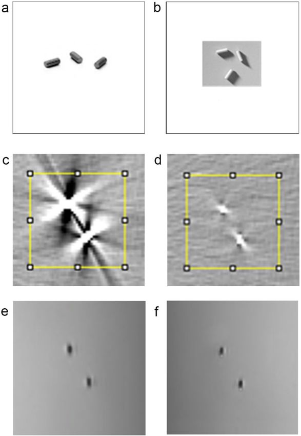
Figure 1. (a) Gold seeds, (b) Polymer seeds, (c) CT of gold seeds with the defined area for the gray-scale
histogram, (d) CT of polymer seeds with the defined area for the gray-scale histograms, (e) MR Co-registered
with CT of gold seeds and (f) MRI Co-registered with CT of polymer seeds.
Polymer fiducials (PolyMark, CIVCO) have been promoted as an alternative to gold because of reduced arti-
fact on X-ray imaging and improved MRI visualization but have only undergone general evaluation9,10. They are
regarded as safe, as they are used clinically in multiple countries having passed appropriate regulatory standards.
Hence, before considering polymer fiducials for prostate cancer clinical use, we investigated the polymer fiducials
in a CT and MR phantom study that approximated the prostate cancer scenario. The aim of the study was to
assess the visibility and characterize the artifacts of the polymer fiducial compared to the standard gold fiducials
on CT and MRI simulation images. If the results of this exploratory phantom study show a possible advantage
for the polymer fiducials, then a clinical study using the methodological developments would be performed to
assess whether they could replace the standard gold fiducials.
Materials and methods
Fiducial markers. Standard gold soft tissue fiducials measuring 0.9 mm × 3 mm and investigational Poly-
Mark (polymer) fiducials markers measuring 1 mm × 3 mm and (CIVCO Medical Solutions, Kalona, Iowa, USA)
were utilized for the study. (Fig. 1a and 1b).
Phantom. A purpose-built, in-house, uniform, gelatine-based Phantom that was tissue equivalent in both
CT and MRI was constructed specifically for the study as described in the following. A rectangular Perspex
box, based on similar phantoms used for linear accelerator imaging quality assurance, was constructed to hold
the phantom material (Fig. 2a). It measured 330 × 230 × 190 mm and was free from metallic components. A
high-density foam grid template was created to ensure reproducibility and avoid positional inaccuracy between
the test groups (Fig. 2a). This template positioned the gold and polymer fiducials precisely at either end of the
phantom to simulate prostate cancer radiotherapy.
Following initial investigations, 200 ml samples were produced using both the 5% and 10% gelatine in addi-
tion to varying the diluent ratio of water to glycerol. Thus, three 5% gelatine mixes and three 10% gelatine mixes
were created, using water to glycerol ratios of 1:1, 2:1, and 3:1 for each. The six samples were then imaged on
CT and MRI.
Scientific Reports | (2021) 11:8931 | https://doi.org/10.1038/s41598-021-88300-w 2
Vol:.(1234567890)www.nature.com/scientificreports/
Figure 2. (a) Perspex box for the phantom with rigid foam plate to guide needles with gold seeds for
reproducibility (b) phantom contained within perspex box.
The 10% gelatine in water to glycerol ratio of 2:1 was selected for the study because of its superior appearance
with respect to tissue equivalence on CT and MRI. A sufficient volume of the 10% gelatine mixed with the 2:1
water:glycerol solution was created and poured into the Perspex box (Fig. 2b).
Once the mixture had set, the three gold and three polymer fiducial markers were placed within the phantom
at mirrored positions using the template and native application apparatus needles (Sterile Placement Needle,
18GA ETW × 20 cm, CIVCO Medical Solutions, Kalona, Iowa, USA). The three gold fiducials and three poly-
mer fiducials were inserted at either end of the phantom around the phantom’s long axis, 5 cm from the short
phantom side, and centered around the mid-depth for both fiducial sets. The positioning of the three fiducials
approximated that used in prostate cancer. The gold and polymer fiducials were positioned far enough from the
sides and each other, so they did not interact with the Perspex or other fiducial set.
The phantom containing the polymer and gold fiducials was then imaged on CT and MRI in a rapid sequence
according to the parameters below. This ensured scanning parameters and the phantom were uniform for all
fiducial measurements on CT and MRI, as the phantom can dry out, changing its physical characteristics and
appearance with time. Alternative phantom material would be required to acquire measurements over a more
prolonged time.
Imaging. The imaging parameters used for study CT and MRI are in accordance with those used for the
clinical simulation for prostate cancer patients.
Simulation CT imaging was performed on a GE Lightspeed RT CT (Boston, Massachusetts, USA) with a
1.25 mm slice width, helical, 0.75 pitch, no gap, 512 × 512 axial resolution, and a 650 mm reconstruction diameter.
Simulation MRI was performed on a 1.5 T Siemens Magneto Avanto Syngo MR B17 (Siemens Healthcare,
Erlangen, Germany). The MRI sequence utilized for this study was a high-resolution 3D T2-weighted scan with
a voxel size of 1 mm, as it is used as the standard planning MRI scan at the center.
Artifact measurement & analysis. Visual assessment, line, and area measurements were analyzed on
DICOM transverse image files in a perpendicular plane corresponding to each fiducial markers center, i.e., three
gold fiducials and three polymer fiducials.
Scientific Reports | (2021) 11:8931 | https://doi.org/10.1038/s41598-021-88300-w 3
Vol.:(0123456789)www.nature.com/scientificreports/
ImageJ software (Rasband, W.S., ImageJ, U. S. National Institute of Health, Bethesda, Maryland, USA) was
used to investigate and quantify the gold and polymer image artifacts fiducials. It was used to assess the indi-
vidual pixel gray-scale values to generate line and surface profiles and histograms of gray-scale for MRI and CT
across a region of interest.
The line profiles graphically highlight the gray-scale of the fiducials and artifacts within the phantom. Whereas
the gray-scale histogram plots mainly represent the phantom and display thepPhantom’s disruption, that is
mainly due to artifact, as the fiducials only occupy a relatively small number of pixels. The transverse CT and MRI
images with the surface plots provide a visual comparison of the fiducials and the surrounding artifact terrain
in the phantom, highlighting the artifact’s interaction with multiple fiducials. This relatively simple and effective
method was developed to illustrate the fiducials’ similarities and differences in MR and CT.
The horizontal line profile plots were generated by centering a 50 mm and 20 mm line over each of the three
gold and three polymer fiducial markers on CT and MR images, respectively. Longer lines were used with CT to
incorporate the greater artifacts produced, particularly by the gold fiducials. The gray-scale reading from each
pixel along the line was measured for each fiducial and normalized relative to the average phantom gray value,
i.e., each pixel gray-scale was divided by the average gray-scale of the phantom material. Each pixel’s average
value for both the three gold and three polymer fiducials was then plotted on the final line plots. The line plots
were used to illustrate the change in the gray-scale relative to the distance across the phantom and fiducials. Line
profile plots thus defined and highlighted the fiducial markers relative to the phantom.
Histograms and surface profiles were derived by centering a 50 mm square region of interest (ROI) over each
fiducial marker on the center transverse slice for each respective seed. The raw gray-scale pixel data for each
fiducial was exported to MS Excel for analysis. The average value for each pixel for both gold and polymer was
used for the histograms and plots.
The histograms show the distribution of pixel number having a particular gray-scale value. The pixel gray-
scale values were normalized relative to the background phantom gray value. Most of the gray-scale histogram
represents the phantom as the fiducials occupy only a small number of pixels. A ratio of 1 represents the average
phantom, whereas the spread of the histogram and slope relates to the artifact and its disruption of the phantom
gray-scale. The relative gray-scale histograms were generated to highlight and contrast the artifact’s effect on the
more uniform phantom gray-scale and indicate the amount of “true” gray-scale phantom seen.
Descriptive statistics were prepared to compare the relative gray-scale histograms for the polymer and gold
fiducials for both the MRI and CT scans. Due to the non-normal distribution in the variation or range in voxel
counts for the CT and MRI histograms, the relative gray values (artifact) attributable to each seed were measured
as percentile ranges (1st to 99th, 5th to 95th, and interquartile range: 25th to 75th percentile).
To further quantify the fiducial visibility and artifact, objective measurements of the contrast-to-noise ratio
(CNR), signal-to-noise ratio (SNR), and artifact index (AI) were c alculated11–13. Two Backgrounds were used
to compare the contrast (CNR) and signal (SNR), i.e. “Phantom” being distant from and not including the arti-
fact, and the Region of Interest being the 50 mm square (“ROI”) containing the artifact. The parameters were
calculated for the three polymer fiducial and three gold fiducials. The presented means (standard deviation, SD)
relate to the CT number for CT scans and gray-scale for the MRI.
The CNR is an indicator of the relative image quality of the fiducial (i.e., visibility) being the ratio of con-
trast/noise. CNR equals the mean difference between the fiducial signal and the Background divided by the
Background’s standard deviation, i.e. CNR = (mean Fiducial − mean Background)/(SD Background). The SNR
compares the desired signal to the level of background noise, or signal/noise. The SNR was calculated from
the quotient of the mean signal of the Background minus the fiducial and the SD where SNR = (Background
mean excluding fiducial) / (Background SD excluding fiducial)11,12. This provides a measure of the impact of the
artifact of the phantom’s image quality surrounding the fiducial. Both background noises and metal artifacts
can increase the standard deviation (SD). When considering SD as an expression of the metal artifacts (AI),
the influence
of the Background (Background SD) should be subtracted. Therefore,
2 the AI was calculated by
AI = (ROI SD but excluding fiducial)2 − Background SD excluding fiducial .
Consent for publication. All authors consent to the publication.
Results
CT scan. The visual analysis showed that both the gold and polymer fiducials are bright and well seen on CT.
However, the gold fiducials produce a greater amount of bright radiating and dark shadowing artifacts than the
polymer seeds’ relatively minor artifact (Fig. 1c,d).
The CT horizontal gray-scale line profile was generated through the fiducial center (Fig. 3a). The gold fiducials
have a higher peak (15,279 in relative gray-scale value) compared to polymer fiducials (2168), indicating they
are brighter, with greater contrast relative to the phantom and the polymer seed. The gold fiducials also exhibit a
broader base indicating a greater spread of gray values, with an approximate relative gray-scale range of 20 mm
compared to approximately 5 mm for the polymer fiducials. Figure 3a is a graphical representation of the higher
contrast and greater artifact of the gold fiducials compared to polymer fiducials.
The histogram of the normalized gray-scale versus pixel number (Fig. 3b) shows the effect of the fiducial
and artifact on the phantom contained in the area of interest. The polymer histogram has a higher peak value
around the centralized phantom gray value of 1, and the base was narrower (1st to 99th percentile: 0.6263 to
1.4848 for polymer fiducials compared to − 3.6061 to 6.6970 for gold fiducials (Table 1) (Fig. 3b) showing that
there is less spread of gray-scale caused by the fiducial artifact and to a lesser extent the small fiducial itself.
The greater amount of the phantom gray-scale being visible with the polymer fiducials is also illustrated by the
Scientific Reports | (2021) 11:8931 | https://doi.org/10.1038/s41598-021-88300-w 4
Vol:.(1234567890)www.nature.com/scientificreports/
Figure 3. (a) line profile of average relative pixel gray values along a 50 mm horizontal line centered on each
fiducial marker on CT, (b) CT histogram of average relative pixel gray values within a 50 × 50 mm square placed
centered on each fiducial marker on CT, polymer and gold.
smaller standard deviation surrounding the mean values and the narrower inter-quartile ranges surrounding
the median and tighter percentile ranges (Table 1).
The mean (SD) of the CNR, SNR and AI of the polymer and gold fiducials are presented in Table 2. The gold
fiducials had a much higher CNR, i.e. contrast than the polymers relative to the phantom (Table 2). However,
the greater contrast of gold was degraded by the artifact to a much greater extent than with the polymer when
considering the CNR relative to the ROI, that includes the artifact. SNR was similar for the gold and polmer
fiducials relative to the phantom. However, the gold signal was degraded by a more considerable amount by the
artifact in the ROI as it obscured the phantom signal. The much larger AI confirms the increased artifact for the
gold fiducial relative to the polymer, that degrades the contrast (CNR) and signal (SNR) of the normal tissue
phantom immediately surrounding the fiducial. This is consistent with the CT appearance.
Surface area gray-scale profiles illustrated the fiducial’s impact on the surrounding phantom and demonstrated
the interaction of multiple fiducials (Fig. 4). The gold fiducial produces a central peak but is surrounded by
Scientific Reports | (2021) 11:8931 | https://doi.org/10.1038/s41598-021-88300-w 5
Vol.:(0123456789)www.nature.com/scientificreports/
Statistic Polymer Gold
CT
Mean (SD) 1.0645 (1.5304) 1.1311 (2.1159)
Median (Inter-quartile Range) 1 (0.9091 to 1.0909) 1 (0.7374 to 1.2727)
5th to 95th percentile 0.7475 to 1.2525 − 0.3333 to 2.4343
1st to 99th percentile 0.6263 to 1.4848 − 3.6061 to 6.6970
MRI
Mean (SD) 1.0369 (0.0505) 1.0390 (0.0455)
Median (Inter-quartile Range) 1.0009 (0.9943 to 1.0075) 1.0004 (0.9949 to 1.0077)
5th to 95th percentile 0.9812 to 1.0163 0.9839 to 1.0169
1st to 99th percentile 0.9636 to 1.0339 0.9748 to 1.0315
Table 1. A statistical comparison of the relative gray-scale histograms (where the phantom normal tissue
gray-scale was normalized to 1) of the polymer versus gold fiducials, generated from a 50 mm square centered
on the fiducial for CT and MRI imaging. The mean (SD standard deviation), median, and percentile ranges
highlight and contrast the artifact’s effect on the more uniform phantom gray-scale. The mean (SD standard
deviation), median, and percentile ranges highlight and contrast the artifact’s effect on the more uniform
phantom gray-scale.
Statistic: Mean (SD) Polymer Gold
CT
CNR (Phantom) 89.4 (25.4) 491.9 (24.7)
CNR (ROI) 54.2 (3) 30.1 (7.9)
SNR (Phantom) 103.5 (3.3) 97 (5.2)
SNR (ROI) 65.6 (15.3) 5.9 (1.3)
AI 13.7 (5.6) 191.6 (41.4)
MRI
CNR (Phantom) 27.3 (5.1) 29.4 (4.4)
CNR (ROI) 21.2 (1.2) 24 (3.5)
SNR (Phantom) 70.2 (9.8) 106.9 (9.1)
SNR (ROI) 52.8 (1.3) 85.4 (12.1)
AI 5.8 (0.9) 4.1 (1)
Table 2. Comparison of the Mean (Standard Deviation, SD) of the Contrast to Noise Ratio (CNR), Signal
to Noise Ratio (SNR) and Artifact Index (AI) of the polymer and gold fiducials in CT and MRI imaging. The
means (SD) relate to the CT number for CT scans and gray-scale for the MRI. Two comparative Backgrounds
were used for CNR and SNR, i.e. distant to the artifact for “Phantom”, and the 50 mm square region of interest
(ROI) containing the artifact for the “ROI”. CNR = Contrast/Noise = (Fiducial mean − Background mean)/
(Background SD). SNR = Signal/Noise = (Background mean excluding fiducial)/(Background SD excluding
2
fiducial). AI = (ROI SD excluding fiducial)2 − Background SD excluding fiducial .
multiple irregular peaks and troughs of gray-scale, representing the noisy artifacts around the fiducial (Fig. 4a).
The polymer fiducial produces a single well-defined peak with little perturbation of the surrounding gentle
undulating terrain of the phantom gray-scale (Fig. 4b). This is further exemplified when two fiducials are in close
proximity to each other, as would not uncommonly be seen in the clinical situation (Fig. 4c,d).
MRI scan. On MRI, the visual analysis showed that the gold and polymer fiducials have a similar appearance
being hypo-intense and thus dark on T2 weighted imaging relative to the phantom (Fig. 1e,f). A mild uniform
hyperintense area around the fiducials was slightly more prominent with the gold fiducials. At one end of the
polymer fiducials, a pronounced hyperintense area was due to the wax used to hold the fiducial in the needle.
This was not present with the gold fiducial. The wax would usually be absorbed in vivo and thus would not be
present on a clinical MRI.
A 20 mm MR line profile was used with MRI because of the minimal artifacts from either fiducial (Fig. 5a).
The gold and polymer plots have a similar appearance. The main differences were that the polymer fiducials had
a slightly darker gray-scale trough than the gold fiducials (polymer relative gray-scale value reaching a minimum
of 0.4181 compared to 0.5328 for gold fiducials). Notably, there are small increases in the gray-scale on either side
of the peak base with the gold fiducials. This represents the small bright or hyperintense hue artifact around the
fiducials, particularly the gold fiducials. The polymer fiducials line profile appears slightly wider than the gold
but may result from the polymer fiducial being slightly wider in diameter or a slight increase in dark artifact
around the polymer fiducial.
Scientific Reports | (2021) 11:8931 | https://doi.org/10.1038/s41598-021-88300-w 6
Vol:.(1234567890)www.nature.com/scientificreports/
Figure 4. Area gray-scale “terrain” of a 50 × 50 mm square centered on (a) Single gold seed, (b) Single polymer
seed, (c) Two adjacent gold seeds, and (d) Two adjacent polymer seeds.
The histogram of the MRI images shows that the polymer and gold fiducials plots are similar in appearance
(Fig. 5b). The polymer MRI normalized histograms show slightly wider percentile ranges (1st to 99th percentile:
0.9636 to 1.0339) when compared to the gold seeds (0.9748 to 1.0315), and a slightly larger standard deviation
about the centralized mean value (0.5050 compared to 0.0455) (Table 1). The surface area profiles of both fiducials
further showed the similarity between the two types of fiducials markers in that they produce minimal artifacts.
The gold and polymer fiducials’ MRI CNR values show much smaller differences for MRI than CT relative
to both phantom and ROI (Table 2). Gold has a higher SNR than polymer, but the AI is almost equivalent. Thus,
while gold has a higher signal, the contrast and artifact are similar to the polymer fiducials and are consistent
with the visual appearance.
Discussion
The increasing precision of prostate radiotherapy requires a fiducial that can be visualized on multi-modality
imaging with minimum artifacts. Therefore, to maintain consistency across imaging, a phantom was developed
that was both CT and MRI tissue-equivalent. This is the first phantom to our knowledge with such dual proper-
ties. This phantom study has shown that polymer fiducials can be well seen on modern three-dimensional imag-
ing, such as MRI and CT. They produce fewer CT artifacts than the benchmark gold fiducials and appear at least
equivalent to gold on MRI. This study further reinforces the findings in a recent prostate CT tissue-equivalent
phantom study that included polymer fiducials but provided further information by developing a phantom that
was both CT and MRI tissue equivalent14.
The accuracy of MRI to planning CT co-registration may be improved with polymer fiducials matching as they
are visible on CT and MRI. It could also reduce interference from artifacts seen with gold that can conceal crucial
soft tissue structures such as the prostate capsule, apex, and dominant intraprostatic lesion (DIL). The accurate
co-registration of MRI and CT is essential as MRI defined volumes are significantly smaller than CT because
less normal tissue is included in target v olumes15–17. It improves the contouring uncertainty, particularly at the
apex and base, and reduces the inter-observer and intra-observer variation6,7,18,19 and the dose to normal tissue20.
MRI also better defines prostate cancer pathology, such as the DIL, extracapsular extension, and seminal vesicle
invasion. Metallic structures, such as gold, cause CT imaging anomalies, including distortion, metal artifacts,
and change in target d ensity21. The distorted CT image can also result in inaccurate planning and delivery if not
accounted for 21. Polymer fiducials may minimize this problem.
Polymer fiducials may provide more accurate co-registration of CBCT to planning CT for treatment verifica-
tion or IGRT. Comparison studies of IGRT/fiducial markers with IMRT versus non-IGRT treatments have shown
a decrease in late GI and GU toxicity2,22,23. In one study, there was also an improvement in clinical outcome2. The
toxicity difference can be attributed to the combination of the IMRT technique with a reduced dose to organs-
at-risk, daily image guidance, and margin reduction that IGRT with fiducials safely permits.
The study’s limitation is that the phantom was a uniform tissue density and a mobile size to provide an
appropriate test environment. However, a human subject will have a greater thickness and heterogeneity, which
may interfere with the fiducial visibility. Furthermore, the study did not analyze other fiducials available on the
market. There are new fiducial markers that produce minimal distortion with CT imaging. Visicoil uses helical
coils of gold to reduce the relative thickness and decrease the equivalent density, thus reducing image artifact24.
Others use a mixture of low-density biocompatible materials and gold particles25. Additional alternatives utilize
lower Z radiopaque materials such as stainless steel, t itanium26, and carbon or ceramic m aterials8,10.
Scientific Reports | (2021) 11:8931 | https://doi.org/10.1038/s41598-021-88300-w 7
Vol.:(0123456789)www.nature.com/scientificreports/
Figure 5. (a) line profile of average relative pixel gray values along a 20 mm line centered on each fiducial
marker on MRI (b) MRI histogram of average relative pixel gray values within a 50 × 50 mm square centered on
each fiducial marker, polymer, and gold on MRI.
Another limitation is that we did not have access to artifact suppression CT21 during the investigation. While
artifact suppression CT is becoming more common in clinical practice, it is not widespread in radiotherapy and
not available for cone-beam CT. Alternative MRI sequences were not used because of the center’s MRI time
limitations. Investigations have shown that other MRI sequences such as T2*2D & T2*3D27 and multi-parametric
MRI with bTFE (balanced steady-state free precession sequence)28 are better at visualizing gold seeds. These
sequences are not used commonly in radiotherapy, but their implementation being investigated with the recent
advent of MRI simulators and MRI linacs in radiotherapy.
Nevertheless, these phantom results indicate that polymer fiducials may be more appropriate for X-ray-based
imaging than the current standard gold marker. They are visualized as a discrete structure on CT and produce
little to no image artifact. Given the CT visualization improvements, combined with equivalent MRI visualization
and similar size and physical appearance, the polymer fiducial could improve radiotherapy treatment planning
and localization. However, they are more expensive than standard gold seeds.
Scientific Reports | (2021) 11:8931 | https://doi.org/10.1038/s41598-021-88300-w 8
Vol:.(1234567890)www.nature.com/scientificreports/
The study was limited to the investigation of CT and MRI simulation images. The rationale was to focus on
the major radiotherapy imaging tools and consider polymer fiducials to aid image co-registration. CT based
imaging, where the gold metallic artifact is an issue, forms the central part of contemporary radiotherapy in
terms of geometry and dosimetry. Whereas MRI has had a secondary function, being co-registered to CT. Its
main function has been the identification of prostate anatomy and cancer pathology. However, MRI is becom-
ing increasingly important as the primary modality of simulation and verification with the clinical introduction
of MRI l inacs29,30. While the polymer fiducials have been approved for radiotherapy verification, future patient
investigations are warranted to thoroughly test them against the standard gold fiducials across all modern veri-
fication modalities, including electronic portal imaging (EPID), cone-beam CT, and MRI. Notably, the polymer
fiducials had less contrast than the gold fiducials, as evident from the CNR calculations. While gold fiducials
are clearly seen for EPID or orthogonal KV verification, it is yet to be shown whether the polymer fiducials can
be visualized with orthogonal matching, particularly lateral planar imaging, where pelvic bones could obscure
the lower contrast fiducials.
We have shown that polymer fiducials have good visibility and reduced artifacts compared to gold fiducials.
The reduced CT artifact could enhance radiotherapy quality and accuracy by improving the visualization of
critical targets such as the prostate apex and allowing for more precise fiducial to fiducial verification, devoid
of obscuring artifact. The polymer fiducials may have utility alongside the development of MRI linacs practice
delivery protocols. However, despite the encouraging results of this preliminary phantom study, polymer fidu-
cials’ real value and cost-effectiveness in radiotherapy must be validated clinically before they can replace gold
fiducial markers. A comparison of polymer and gold fiducials in prostate cancer patients is indicated based on
these encouraging results.
Data availability
Research data is stored in an institutional repository and will be shared upon request to the corresponding author.
Received: 10 November 2020; Accepted: 6 April 2021
References
1. O’Neill, A. G., Jain, S., Hounsell, A. R. & O’Sullivan, J. M. Fiducial marker guided prostate radiotherapy: a review. Br. J. Radiol. 89,
20160296. https://doi.org/10.1259/bjr.20160296I (2016).
2. Zelefsky, M. J. et al. Improved clinical outcomes with high-dose image guided radiotherapy compared with non-IGRT for the
treatment of clinically localized prostate cancer. Int. J. Radiat. Oncol. Biol. Phys. 84, 125–129. https://doi.org/10.1016/j.ijrobp.2011.
11.047I (2012).
3. Parker, C. Magnetic resonance imaging in the radiation treatment planning of localized prostate cancer using intra-prostatic
fiducial markers for computed tomography co-registration. Radiother. Oncol. 66, 217–224. https://d oi.o rg/1 0.1 016/s 0167-8 140(02)
00407-3I (2003).
4. Khoo, V. S. & Joon, D. L. New developments in MRI for target volume delineation in radiotherapy. Br J Radiol 79 Spec No 1, S2–15.
https://doi.org/10.1259/bjr/41321492I (2006).
5. Chang, J. H. et al. MRI scans significantly change target coverage decisions in radical radiotherapy for prostate cancer. J. Med.
Imaging Radiat. Oncol. 58, 237–243. https://doi.org/10.1111/1754-9485.12107I (2014).
6. Villeirs, G. M. & De Meerleer, G. O. Magnetic resonance imaging (MRI) anatomy of the prostate and application of MRI in radio-
therapy planning. Eur. J. Radiol. 63, 361–368. https://doi.org/10.1016/j.ejrad.2007.06.030I (2007).
7. Rasch, C. et al. Definition of the prostate in CT and MRI: a multi-observer study. Int. J. Radiat. Oncol. Biol. Phys. 43, 57–66 (1999).
8. Chen, Y. et al. Fiducial markers in prostate for kV imaging: quantification of visibility and optimization of imaging conditions.
Phys. Med. Biol. 57, 155–172. https://doi.org/10.1088/0031-9155/57/1/155I (2012).
9. Chan, M. F., Cohen, G. N. & Deasy, J. O. Qualitative evaluation of fiducial markers for radiotherapy imaging. Technol. Cancer Res.
Treat. 14, 298–304. https://doi.org/10.1177/1533034614547447I (2015).
10. Handsfield, L. L., Yue, N. J., Zhou, J., Chen, T. & Goyal, S. Determination of optimal fiducial marker across image-guided radiation
therapy (IGRT) modalities: visibility and artifact analysis of gold, carbon, and polymer fiducial markers. J. Appl. Clin. Med. Phys.
13, 3976. https://doi.org/10.1120/jacmp.v13i5.3976I (2012).
11. Hu, Y. et al. Value and clinical application of orthopedic metal artifact reduction algorithm in CT scans after orthopedic metal
implantation. Korean J. Radiol. 18, 526–535. https://doi.org/10.3348/kjr.2017.18.3.526I (2017).
12. Baskan, O., Erol, C., Ozbek, H. & Paksoy, Y. Effect of radiation dose reduction on image quality in adult head CT with noise-
suppressing reconstruction system with a 256 slice MDCT. J. Appl. Clin. Med. Phys. 16, 5360–5360. https://doi.o rg/1 0.1 120/j acmp.
v16i3.5360I (2015).
13. Brombal, L. et al. Image quality comparison between a phase-contrast synchrotron radiation breast CT and a clinical breast CT:
a phantom based study. Sci Rep 9, 17778. https://doi.org/10.1038/s41598-019-54131-zI (2019).
14. Osman, S. O. S. et al. Fiducial markers visibility and artefacts in prostate cancer radiotherapy multi-modality imaging. Radiat.
Oncol. 14, 237. https://doi.org/10.1186/s13014-019-1447-1I (2019).
15. Hentschel, B., Oehler, W., Strauss, D., Ulrich, A. & Malich, A. Definition of the CTV prostate in CT and MRI by using CT-MRI
image fusion in IMRT planning for prostate cancer. Strahlenther. Onkol. 187, 183–190. https://d oi.o
rg/1 0.1 007/s 00066-0 10-2 179-1 I
(2011).
16. Roach, M. 3rd., Faillace-Akazawa, P., Malfatti, C., Holland, J. & Hricak, H. Prostate volumes defined by magnetic resonance
imaging and computerized tomographic scans for three-dimensional conformal radiotherapy. Int. J. Radiat. Oncol. Biol. Phys. 35,
1011–1018 (1996).
17. Sannazzari, G. L. et al. CT-MRI image fusion for delineation of volumes in three-dimensional conformal radiation therapy in the
treatment of localized prostate cancer. Br. J. Radiol. 75, 603–607. https://doi.org/10.1259/bjr.75.895.750603I (2002).
18. Khoo, E. L. et al. Prostate contouring variation: can it be fixed?. Int. J. Radiat. Oncol. Biol. Phys. 82, 1923–1929. https://doi.org/10.
1016/j.ijrobp.2011.02.050I (2012).
19. Khoo VS & DL, J. in Image Guided Radiation Therapy: A Clinical Perspective (ed Arnold R Mundt A) (Peoples Medical Publishing
House, 2006).
20. Buyyounouski, M. K. et al. Intensity-modulated radiotherapy with MRI simulation to reduce doses received by erectile tissue
during prostate cancer treatment. Int. J. Radiat. Oncol. Biol. Phys. 58, 743–749. https://doi.org/10.1016/S0360-3016(03)01617-1I
(2004).
Scientific Reports | (2021) 11:8931 | https://doi.org/10.1038/s41598-021-88300-w 9
Vol.:(0123456789)www.nature.com/scientificreports/
21. Wei, J., Sandison, G. A., Hsi, W. C., Ringor, M. & Lu, X. Dosimetric impact of a CT metal artefact suppression algorithm for proton,
electron and photon therapies. Phys. Med. Biol. 51, 5183–5197. https://doi.org/10.1088/0031-9155/51/20/007I (2006).
22. Sveistrup, J. et al. Improvement in toxicity in high risk prostate cancer patients treated with image-guided intensity-modulated
radiotherapy compared to 3D conformal radiotherapy without daily image guidance. Radiat. Oncol. 9, 44. https://d oi.o
rg/1 0.1 186/
1748-717X-9-44I (2014).
23. Kok, D. et al. Late toxicity and biochemical control in 554 prostate cancer patients treated with and without dose escalated image
guided radiotherapy. Radiother. Oncol. 107, 140–146. https://doi.org/10.1016/j.radonc.2013.04.007I (2013).
24. Gates, L. L. et al. Stability of serrated gold coil markers in prostate localization. J. Appl. Clin. Med. Phys. 12, 3453 (2011).
25. Lim, Y. K. et al. Microscopic gold particle-based fiducial markers for proton therapy of prostate cancer. Int. J. Radiat. Oncol. Biol.
Phys. 74, 1609–1616. https://doi.org/10.1016/j.ijrobp.2009.02.076I (2009).
26. Newhauser, W. et al. Monte Carlo simulations of the dosimetric impact of radiopaque fiducial markers for proton radiotherapy of
the prostate. Phys. Med. Biol. 52, 2937–2952. https://doi.org/10.1088/0031-9155/52/11/001I (2007).
27. Tanaka, O. et al. Comparison of MRI sequences in ideal fiducial maker-based radiotherapy for prostate cancer. Rep. Pract. Oncol.
Radiother. 22, 502–506. https://doi.org/10.1016/j.rpor.2017.10.002I (2017).
28. Dinis Fernandes, C. et al. Prostate fiducial marker detection with the use of multi-parametric magnetic resonance imaging. Phys.
Imaging Radiat. Oncol. 1, 14–20. https://doi.org/10.1016/j.phro.2017.02.001I (2017).
29. Hunt, A., Hansen, V. N., Oelfke, U., Nill, S. & Hafeez, S. Adaptive radiotherapy enabled by MRI guidance. Clin. Oncol. (R Coll.
Radiol.) 30, 711–719. https://doi.org/10.1016/j.clon.2018.08.001I (2018).
30. Murray, J. & Tree, A. C. Prostate cancer—advantages and disadvantages of MR-guided RT. Clin. Transl. Radiat. Oncol. 18, 68–73.
https://doi.org/10.1016/j.ctro.2019.03.006I (2019).
Acknowledgments
Leanne Elich and alphaXRT for supplying the three polymer seeds.
Author contributions
D.L.J., D.S., M.S. and V.K. contributed to the concept, design and methodology of the study. D.L.J. and D.S.
designed and built the phantom. D.L.J., D.S. and B.H. carried out the experiment and acquired the data. D.L.J.,
D.S., B.H. and M.T. performed the analysis, statistics and designed the figures and table. D.L.J., D.S., B.H., M.T.,
M.S. and V.K. were involved in the interpretation of the data and analysis. D.L.J., D.S., M.T., B.H., M.S., T.J.,
W.L.O. and V.K. drafted the article. All authors, D.L.J., D.S., M.T., M.S., B.H., W.L.O., F.F., T.J., M.W., M.C., K.R. &
V.K. were involved in the critical revision of the article. All authors, D.L.J., D.S., M.T., M.S., B.H., W.L.O., F.F., T.J.,
M.W., M.C., K.R. & V.K. agree to be accountable for the integrity and final approval of the version to be published.
Funding
alphaXRT company supplied the three polymer seeds for the study.
Competing interests
On behalf of the authors, Daryl Lim Joon, Drew Smith, Mark Tacey, Michal Schneider, Wee Loon Ong, Farshad
Foroudi, Trish Jenkins, Morikatsu Wada, Michael Chao, Benjamin Harris, Kym Rykers, Vincent Khoo—all
authors do not have a conflict of interest, i.e., they do not have financial and personal relationships with other
people or organizations that could inappropriately influence (bias) their work except that alphaXRT company
supplied the three polymer seeds for the study.
Additional information
Correspondence and requests for materials should be addressed to V.K.
Reprints and permissions information is available at www.nature.com/reprints.
Publisher’s note Springer Nature remains neutral with regard to jurisdictional claims in published maps and
institutional affiliations.
Open Access This article is licensed under a Creative Commons Attribution 4.0 International
License, which permits use, sharing, adaptation, distribution and reproduction in any medium or
format, as long as you give appropriate credit to the original author(s) and the source, provide a link to the
Creative Commons licence, and indicate if changes were made. The images or other third party material in this
article are included in the article’s Creative Commons licence, unless indicated otherwise in a credit line to the
material. If material is not included in the article’s Creative Commons licence and your intended use is not
permitted by statutory regulation or exceeds the permitted use, you will need to obtain permission directly from
the copyright holder. To view a copy of this licence, visit http://creativecommons.org/licenses/by/4.0/.
© The Author(s) 2021
Scientific Reports | (2021) 11:8931 | https://doi.org/10.1038/s41598-021-88300-w 10
Vol:.(1234567890)You can also read