Agilent N4238A/B FB-DIMM Parametric Slot Probe User's Guide
←
→
Page content transcription
If your browser does not render page correctly, please read the page content below
Agilent N4238A/B
FB-DIMM Parametric Slot Probe

User’s Guide
Notices                                          Warranty                                          Safety Notices
© Agilent Technologies, Inc. 2005                The material contained in this document is
                                                 provided “as is,” and is subject to being
                                                                                                     CAUTION
No part of this manual may be reproduced in
any form or by any means (including electronic   changed, without notice, in future editions.
storage and retrieval or translation into a      Further, to the maximum extent permitted by        A CAUTION notice denotes a
foreign language) without prior agreement and    applicable law, Agilent disclaims all              hazard. It calls attention to an
written consent from Agilent Technologies,       warranties, either express or implied, with
                                                 regard to this manual and any information
                                                                                                    operating procedure, practice, or
Inc. as governed by United States and
international copyright laws.                    contained herein, including but not limited to     the like that, if not correctly
                                                 the implied warranties of merchantability and      performed or adhered to, could
                                                 fitness for a particular purpose. Agilent shall
Manual Part Number                                                                                  result in damage to the product or
                                                 not be liable for errors or for incidental or
N4238-97000                                      consequential damages in connection with
                                                                                                    loss of important data. Do not
                                                 the furnishing, use, or performance of this        proceed beyond a CAUTION notice
Print History                                    document or of any information contained           until the indicated conditions are
                                                 herein. Should Agilent and the user have a         fully understood and met.
N4238-97000, February 2008
                                                 separate written agreement with warranty
Printed in USA                                   terms covering the material in this document
Agilent Technologies, Inc.                       that conflict with these terms, the warranty
1900 Garden of the Gods Road                     terms in the separate agreement shall
Colorado Springs, CO 80907 USA                   control.                                            WARNING
Trademark Acknowledgements                       Technology Licenses                                A WARNING notice denotes a
                                                 The hardware and/or software described in          hazard. It calls attention to an
                                                 this document are furnished under a license        operating procedure, practice, or
                                                 and may be used or copied only in accordance
                                                 with the terms of such license.
                                                                                                    the like that, if not correctly
                                                                                                    performed or adhered to, could
                                                 Restricted Rights Legend                           result in personal injury or death.
                                                 If software is for use in the performance of a     Do not proceed beyond a
                                                 U.S. Government prime contract or                  WARNING notice until the
                                                 subcontract, Software is delivered and licensed    indicated conditions are fully
                                                 as “Commercial computer software” as
                                                 defined in DFAR 252.227-7014 (June 1995), or
                                                                                                    understood and met.
                                                 as a “commercial item” as defined in FAR
                                                 2.101(a) or as “Restricted computer software”
                                                 as defined in FAR 52.227-19 (June 1987) or any
                                                 equivalent agency regulation or contract
                                                 clause. Use, duplication or disclosure of
                                                 Software is subject to Agilent Technologies’
                                                 standard commercial license terms, and non-
                                                 DOD Departments and Agencies of the U.S.
                                                 Government will receive no greater than
                                                 Restricted Rights as defined in FAR 52.227-
                                                 19(c)(1-2) (June 1987). U.S. Government users
                                                 will receive no greater than Limited Rights as
                                                 defined in FAR 52.227-14 (June 1987) or DFAR
                                                 252.227-7015 (b)(2) (November 1995), as
                                                 applicable in any technical data.

2                                                                                                     FB-DIMM Parametric Slot Probe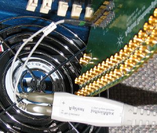
Introduction

           Introduction—4

           N4238A/B DIMM Parametric Slot Probe Description—5
                   Fixture Technical Feature Summary—5
                   Equipment Supplied—6

           N4238A—6

           N4238B—6

           FB-DIMM Parametric Slot Probe Operation—7
                   Installing the Fixture—7
                   Connecting test equipment to FBD high-speed signal pins of DIMM connector—7
                   De-embedding the fixture response using on-board SOLT calibration networks—
                   8
                   Connecting test equipment to FBD high-speed signal pins of DIMM—9
                   Connecting the reference clock source to the DIMM—9
                   Configuring the DIMM test pins—10
                   De-embedding the fixture using on-board SOLT calibration networks—10

           Characteristics, Regulatory, and Safety Information—11
                   Operating Characteristics—11

           WEEE Compliance—11

           Safety Notices—13
                   Warnings—13
                   To clean the instrument—13
                   Safety Symbols—13

FB-DIMM Parametric Slot Probe                                                                       3
Introduction
Introduction
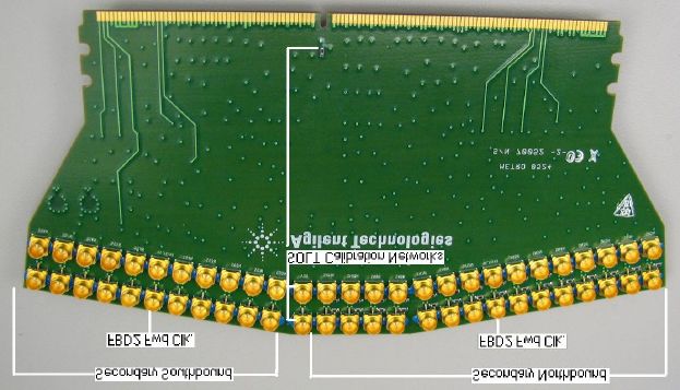
This User's Guide provides operation and programming information
for the N4238A/B FB-DIMM parametric slot probe. This information
also applies to the N4238B probe, which has a reduced cable set. The
illustrations below show the overall features and connection points
for the probe:
4 FB-DIMM Parametric Slot ProbeN4238A/B DIMM Parametric Slot Probe Description
N4238A/B DIMM Parametric Slot Probe Description
The N4238A/B FBD slot parametric test fixture is designed to allow
accurate and repeatable measurements of key operating parameters
and specifications of Fully Buffered DIMM (FBD) modules and
motherboards. It allows parametric test equipment such as
oscilloscopes, pulse generators, bit error ratio testers, TDRs, and
vector network analyzers to be connected to the pins of a JEDEC
standard FB-DIMM module connector using standard 50 ohm
interconnect.
Fixture Technical Feature Summary
§ 50 ohm controlled impedance connection to JEDEC standard FB-
DIMM module connector. Each signal is routed as a 50 ohm
(±5%) single ended signal from the DIMM connector pin to test
equipment connection points. Wide trace separation and
multiple routing layers ensure good isolation between signals.
All DIMM connector signals are probed.
§ Calibration coupons are provided to allow de-embedding of the
fixture using SOLT calibration.
§ SMP male connectors are provided for all FBD high-speed
channel signals:
§ Secondary Northbound and Primary Southbound signals
§ Reference clock
§ Primary Northbound and Secondary Southbound signals
§ 0.050” Header connections provided for:
§ All JEDEC defined DIMM module test pins
§ All module power supplies
§ SPD address, data, and clock signals
§ FBD Forwarded clock signals are supported for FBD2 operation
§ Coaxial cables allow arbitrary connection of DIMM input and
output signals to allow the probe to be configured for:
§ Capture of eye diagrams for memory controller and AMB
transmitted signals
§ Driving stimulus onto the backplane for BER, stressed eye,
and functional test
§ Loopback of Southbound signals onto the Northbound lanes
for IBIST and other testing.
§ Injection of noise and jitter into the channel for stressed eye
testing
§ Adding skew to individual lanes
§ Creation of failover conditions
§ Creating lane swap and polarity reversal conditions
FB-DIMM Parametric Slot Probe 5N4238A/B DIMM Parametric Slot Probe Description
Equipment Supplied
N4238A
The following components have been shipped with your N4238A
fixture:
§ N4238A-62402 slot parametric probe
§ 3 pairs of phase matched (2ps) 50 ohm (±5%) SMP female to SMA
male adapter cables
§ Four SMP male to SMP female adapters
§ 25 pairs of 2ps phase matched SMP female/SMP female jumper
cables
§ This User's Guide
N4238B
The following components have been shipped with your N4238B
fixture:
§ N4238A-62402 slot parametric probe
§ 3 pairs of phase matched (2ps) 50 ohm (±5%) SMP female to SMA
male adapter cables
Part numbers are subject to change without notice.
6 FB-DIMM Parametric Slot ProbeFB-DIMM Parametric Slot Probe Operation
FB-DIMM Parametric Slot Probe Operation
Installing the Fixture
The N4238A/B fixture is installed by inserting it into any available
FBD slot.
Connecting test equipment to FBD high-speed signal pins of DIMM
connector
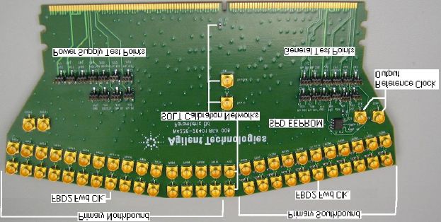
SMP male connectors are provided for each high-speed signal on the
FBD connector. The signal attached to each connector is indicated on
the fixture silkscreen as described in the table below:
Input to probe /
Silkscreen label Signal Output from probe
PS, PSN Primary Southbound Pair Output
SS, SSN Secondary Southbound Pair Input
PN, PNN Primary Northbound Pair Input
SS, SSN Secondary Southbound Pair Output
SCK, SCKn Reference clock Output
SHORT SMP shorted immediately to Vss Cable Calibration
Open SMP with no signal connection Cable Calibration
Thru In, Thru Out SMPs connected by a trace double the SOLT Calibration
length of the PS/SS/PN/SN traces
50 ohm SMP connected to 50 ohm load to Vss SOLT Calibration
through a trace matched to length of
PS/SS/PN/SN traces
VSS SMP connected to VSS through a SOLT Calibration
trace matched to length of
PS/SS/PN/SN traces
Each connection to the FBD connector is via a 50 ohm (±10%) single
ended connection. All traces are length matched to better than 2ps.
The supplied SMP to SMA adapter cables can be used to connect the
PS and SN output signals to a scope or the analyzer inputs of a BERT.
They can also be connected to an instrument such as a VNA or TDR
for making measurements of the interconnect characteristics of the
backplane or FBD connectors.
The supplied SMP female to SMA male adapter cables may be used to
connect the SS and PN input signals to a pulse or pattern generator,
or a TDR or VNA.
SMP male connectors are provided for connecting to the AMB
reference clock driven onto a module.
FB-DIMM Parametric Slot Probe 7FB-DIMM Parametric Slot Probe Operation
All test, power supply, and SPD signals defined in the FB-DIMM
specification are connected to 0.050” pitch headers that are
compatible with Agilent InfiniMax scope probes or the E5381A
differential flying lead set for Agilent logic analyzers. The labels on
the probe identify which signal each header is connected to. These
headers are compatible with the Agilent InfiniMax oscilloscope
probing system, as well as the E5381A logic analyzer differential
flying lead probes. The pinout of each header is the same, with the
leftmost pin carrying the signal identified on the silkscreen and the
rightmost pin connected to Vss. The middle pin is left open. The
illustration below show how an Agilent InfiniMax probe would be
connected to the N4238A/B probe to perform power supply noise
measurements. An Agilent 1134A active probe is shown using an
E2669 differential socketed probe head to connect to the VCC test
point header on the FBD slot parametric probe.
De-embedding the fixture response using on-board SOLT
calibration networks
SOLT style calibration networks are provided to allow the reference
plane of measurement instruments to be extended to the gold fingers
of the DIMM connector. Separate calibration coupons are provided
for the top and bottom sides of the fixture because their
characteristics may differ. A single pair of SMP male connectors
provide a “thru” calibration connection.
8 FB-DIMM Parametric Slot ProbeFB-DIMM Parametric Slot Probe Operation
Connecting test equipment to FBD high-speed signal pins of DIMM
SMP male connectors are provided for each DIMM high-speed signal.
The signal attached to each connector is indicated on the fixture.
Each connection to the DIMM is via a 50 ohm (±5%) single ended
connection. All traces to the DIMM are length matched to better than
2ps. The SMP female to SMA male cables supplied with the fixture
may be used to connect test equipment such as oscilloscopes, TDRs,
VNAs, BERT/ParBERTs, and pulse generators to the DIMM.
Connecting the reference clock source to the DIMM
Two SMP connectors are provided to connect to the differential
reference clock input. These connectors are labeled as “SCK” and
SCKn” on the fixture. Each provides a 50 ohm single ended trace to
the DIMM reference clock input pins.
FB-DIMM Parametric Slot Probe 9FB-DIMM Parametric Slot Probe Operation
Configuring the DIMM test pins
Some pins are accessible using 0.10” headers provided on the fixture.
The DIMM gold finger is connected to one pin of the header
De-embedding the fixture using on-board SOLT calibration networks
SOLT style calibration networks are provided to allow the reference
plane of measurement instruments to be extended to the gold fingers
of the DIMM.
The SMP labeled “GND” has its signal pin connected to GND right at
the SMP connector. The SMP labeled “OPEN” leaves its signal pin
open. These two connections may be use to measure the
characteristics the cables to be connected to the fixture. A 50 ohm
load right at the SMP connector is not provided, and can be created
by soldering a 50 ohm resistor between the pin and body of the
“OPEN” SMP connector.
The “SHORT”, “OFFSET OPEN”, and “50 ohm Load” SMP connectors
have traces routed respectively to a GND connection, an open circuit,
and a 50 ohm resistor to ground. The trace length is matched to the
trace lengths from the high-speed signals to the FB-DIMM connector
to within 1 mil. The “THRU” calibration connection is provided by
the pair of SMPs marked “THRU”. The trace length between these
SMPs is exactly twice the length of the traces from a high-speed
signal SMP and the FB-DIMM connector. When performing the
“THRU” calibration the delay of the “THRU” connection should
therefore be stated to be 0ps to the calibration software (such as
PLTS).
10 FB-DIMM Parametric Slot ProbeCharacteristics, Regulatory, and Safety Information
Characteristics, Regulatory, and Safety Information
Operating Characteristics
The following operating characteristics are not specifications, but are
typical operating characteristics for the analysis probe with
interposer.
Table 1 Environmental Characteristics (Operating)
Temperature 20° to + 30° C (+68° to +86° F)
Altitude 4,600 m (15,000 ft)
Humidity Up to 50% noncondensing. Avoid sudden, extreme temperature changes which could cause
condensation on the circuit board.
For indoor use only.
Table 2 Inputs and Outputs
To probe Memory bus signals from target system
From probe High-density connectors for an Agilent 16700- or 16900-series logic analysis system.
WEEE Compliance
This product complies with the WEEE Directive (2002/96/EC) marking
requirements. The affixed label indicates that you must not discard this
electrical/electronic product in domestic household waste.
Product Category: With reference to the equipment types in the WEEE
Directive Annex I, this product is classed as a "Monitoring and Control
Instrumentation" product.
Do not dispose in domestic household waste.
To return unwanted products, contact your local Agilent office, or see
www.agilent.com for more information.
FB-DIMM Parametric Slot Probe 11Characteristics, Regulatory, and Safety Information 12 FB-DIMM Parametric Slot Probe
Safety Notices

Safety Notices
                                This apparatus has been designed and tested in accordance with IEC
                                Publication 1010, Safety Requirements for Measuring Apparatus, and
                                has been supplied in a safe condition. Before applying power, verify
                                that the correct safety precautions are taken (see the following
                                warnings). In addition, note the external markings on the instrument
                                that are described under "Safety Symbols."

               Warnings
                                Use only the recommended power supply.
                                If you energize this instrument by an auto transformer (for voltage
                                reduction or mains isolation), the common terminal must be
                                connected to the earth terminal of the power source.
                                Whenever it is likely that the ground protection is impaired, you
                                must make the instrument inoperative and secure it against any
                                unintended operation.
                                Service instructions are for trained service personnel. To avoid
                                dangerous electric shock, do not perform any service unless qualified
                                to do so. Do not attempt internal service or adjustment unless
                                another person, capable of rendering first aid and resuscitation, is
                                present.
                                Do not install substitute parts or perform any unauthorized
                                modification to the instrument.
                                Capacitors inside the instrument may retain a charge even if the
                                instrument is disconnected from its source of supply.
                                Do not operate the instrument in the presence of flammable gasses or
                                fumes. Operation of any electrical instrument in such an
                                environment constitutes a definite safety hazard.
                                Do not use the instrument in a manner not specified by the
                                manufacturer.

               To clean the instrument
                                Do not attempt to clean this product.

               Safety Symbols
                                            Instruction manual symbol: the product is marked with this symbol when
                                  !         it is necessary for you to refer to the instruction manual in order to
                                            protect against damage to the product.
                                            Hazardous voltage symbol.

                                            Earth terminal symbol: Used to indicate a circuit common connected to
                                            grounded chassis.

FB-DIMM Parametric Slot Probe                                                                                       13
Safety Notices
Manual Part Number N4238-97000
Printed in USA
*N4238-97000*
*N4238-97000*
14 FB-DIMM Parametric Slot ProbeYou can also read