AN958: Debugging and Programming Interfaces for Custom Designs
←
→
Page content transcription
If your browser does not render page correctly, please read the page content below
AN958: Debugging and Programming
Interfaces for Custom Designs

The Silicon Labs MCU and Wireless Starter Kits and Simplicity
                                                                                          KEY POINTS
Studio provide a powerful development and debug environment.
In order to take advantage of these capabilities and features on custom hardware, Sili-   • Wireless starter kits along with Simplicity
                                                                                            Studio provide a powerful development
con Labs recommends including debugging and programming interface connector(s) in
                                                                                            and debug environment
custom hardware designs. Possible options include full support of all debugging and
                                                                                          • Use the debugging and programming
programming capabilities of the STK, to serial wire programming only. This application
                                                                                            interface connector(s) to take advantage of
note describes the benefits of including these connector interfaces in custom hardware      these capabilities
designs and provides the details regarding these interfaces.

                                                 Simplicity Debug Adapter Board

silabs.com | Building a more connected world.                                                                                      Rev. 0.9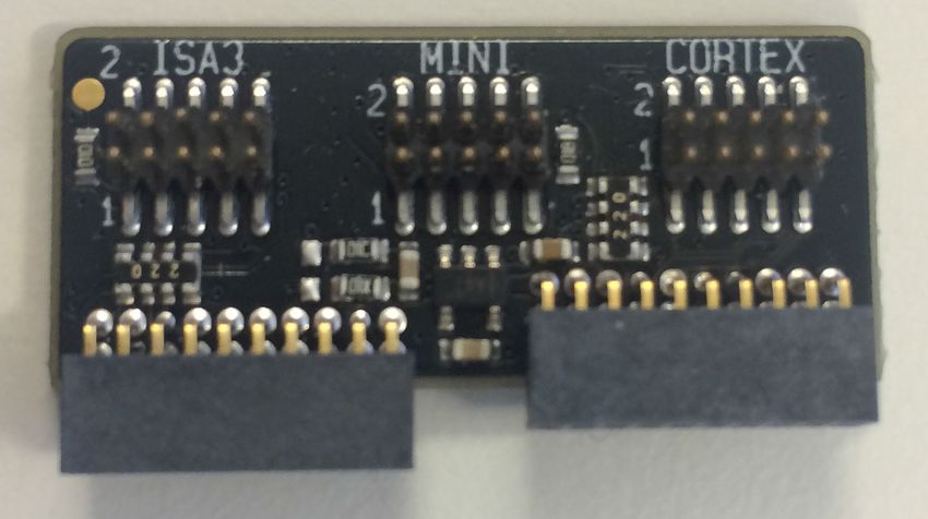
AN958: Debugging and Programming Interfaces for Custom Designs
                                                                                                                   Device Compatibility

1. Device Compatibility

This application note supports multiple device families, and some functionality is different depending on the device.
 • 32-bit MCUs
 • 8-bit MCUs
 • 32-bit Wireless MCUs
 • 32-bit Wireless Gecko Modules

silabs.com | Building a more connected world.                                                                                 Rev. 0.9 | 2
AN958: Debugging and Programming Interfaces for Custom Designs
Background
2. Background
The Silicon Labs MCU Starter Kit (STK) and Wireless Starter Kit (WSTK) provide a powerful development and debug environment
when used with Simplicity Studio. The STK and WSTK provide several debug capabilities and features, including the following:
• SWD (serial wire debug)
• 2-pin serial wire debug interface for programming and debugging, using the pins SWCLK and SWDIO.
• JTAG
• 4-wire interface for programming and debugging, using the pins TCK, TMS, TDI, and TDO.
• C2 interface (for 8-bit devices)
• 2-wire programming interface used by most Silicon Labs 8-bit MCUs.
• See "AN124: Pin Sharing Techniques for the C2 Interface", which discusses pin sharing for C2 devices.
• ETM* (embedded trace macrocell)
• Debug component which enables reconstruction of program execution, and is designed as a high-speed, low-power debug tool
that only supports instruction trace.
• AEM (advanced energy monitoring)
• Accurate high-speed current measurements and energy debugging/profiling when the STK/WSTK power selection switch is in the
AEM position. Use with Simplicity Studio Energy Profiler perspective.
• PTI (packet trace interface [WSTK only])
• Physical layer (PHY) level PTI for effective network-level debugging. Monitors all the PHY transmit and receive packets between
the MAC and baseband modules within the radio without affecting normal operation.
• VCOM (virtual COM port)
• UART COM port interface to the target from the debugger (pass-through UART).
• Virtual UART
• SWD-based virtual UART interface to the target from the debugger, available through the SWD interface (SWDIO, SWCLK, and
SWO).
These features are available via several different interface means, depending on the features required by the custom target hardware
design and the board space available for these interface connectors or test points. These details are discussed in the following sec-
tions.
Note:
1. The STK and WSTK support ETM only when using an external debugger which supports ETM Capture. The STK and WSTK do
not include an ETM capture unit. Only devices that have an ETM macrocell will support ETM capture, regardless of the debugger
capabilities. Consult the corresponding MCU or Wireless device data sheet for details regarding whether ETM is supported on the
device. Silicon Labs MCU and Wireless Development Kits may include support for ETM. Consult the kit documentation for further
details.
2. To ensure that the STK and WSTK properly recognize the connected target device, go to the target adapter in the "Debug Adapt-
ers" list in Simplicity Studio, right-click on the target adapter, select "Device Configuration", select the "Device Hardware" tab, and
enter the full part number of the external device target under "Target Part".
silabs.com | Building a more connected world. Rev. 0.9 | 3AN958: Debugging and Programming Interfaces for Custom Designs
Interface Feature Mapping
3. Interface Feature Mapping
The table below summarizes the capabilities and features of the various interfaces described in the following sections. Click on the col-
umn header hyperlinks to go directly to the section describing each specific interface.
Table 3.1. Interface Capabilities and Features
Feature 20-pin Standard 20-pin Simplicity Debug Adapter Board Interfaces Tag-Connect
ARM Cortex Simplicity (Standard or Tag-Connect 10-pin cable) 6-pin
Debug+ETM Connector Interface
Connector Mini Cortex Debug ISA3 Packet
Simplicity Connector Trace Port
Connector Connector
SWD (serial wire debug) X X X X X
JTAG X X X
C2 X X
ETM (embedded trace X
module)
AEM (advanced energy X X
monitoring)
PTI (packet trace interface) X X X
VCOM (virtual COM port) X X
Virtual UART X X X X X
silabs.com | Building a more connected world. Rev. 0.9 | 4AN958: Debugging and Programming Interfaces for Custom Designs
Connector Interfaces
4. Connector Interfaces
This section presents the standard debug connector interfaces provided by the STK and WSTK, as well as recommendations for includ-
ing connector interfaces on custom target hardware designs in order to utilize these debug capabilities and features.
4.1 Standard ARM Cortex Debug+ETM Connector
In cases where ETM and/or JTAG debug capabilities and features are required on custom target hardware, a 20-pin (2x10, 1.27 mm
pitch) standard ARM Cortex Debug+ETM Connector (similar to Sullins™ part number GRPB102VWQS) should be included in the de-
sign. A 20-pin 2x10 1.27 mm pitch ribbon cable (similar to Samtec™ part number FFSD-10-D-6.00-01-N) is required for the connection
between the WSTK debug connector and the custom target hardware board connector.
Note: Silicon Labs deviates slightly from the ARM standard, as this version of the connector includes the key pin.
4.1.1 Connector Pin-Out
A pin-out for this debug connector interface is provided in the figure and table below. If ETM and/or JTAG are not required, see
5. Alternative Interfaces for other debug interface options to include on target hardware designs.
VTARGET 1 2 TMS / SWDIO / C2D
GND 3 4 TCK / SWCLK / C2CK
GND 5 6 TDO / SWO
NC 7 8 TDI / C2Dps
Cable Detect 9 10 RESET / C2CKps
NC 11 12 TRACECLK
NC 13 14 TRACED0
GND 15 16 TRACED1
GND 17 18 TRACED2
GND 19 20 TRACED3
Figure 4.1. Debug Connector
silabs.com | Building a more connected world. Rev. 0.9 | 5AN958: Debugging and Programming Interfaces for Custom Designs
Connector Interfaces
Table 4.1. Debug Connector Pin Descriptions
Pin Number(s) Function Note
1 VTARGET Reference voltage on the target application. Used for shifting logical signal
levels between target and debugger.
2 TMS / SDWIO / C2D JTAG test mode select, Serial Wire data or C2 data
4 TCK / SWCLK / C2CK JTAG test clock, Serial Wire clock or C2 clock
6 TDO/SWO JTAG test data out or Serial Wire Output
8 TDI / C2Dps JTAG test data in, or C2D "pin sharing" function1
10 RESET / C2CKps Target device reset, or C2CK "pin sharing" function
12 TRACECLK Not connected
14 TRACED0 Not connected
16 TRACED1 Not connected
18 TRACED2 Not connected
20 TRACED3 Not connected
9 Cable detect Connect to ground
11, 13 NC Not connected
3, 5, 15, 17, 19 GND
Note:
1. See "AN124: Pin Sharing Techniques for the C2 Interface", which discusses pin sharing for C2 devices.
4.1.2 Connector Footprint
An example component footprint is from Sullins for part number GRPB102VWQS. Refer to http://www.sullinscorp.com/catalogs/
82_PAGE90-91_.050_MALE_HDR_ST_RA_SMT.pdf for details on this connector footprint for the custom target hardware PCB.
4.2 20-pin Simplicity Connector
If AEM, PTI, and VCOM functionality are desired, include the 20-pin (2x10, 1.27 mm pitch) Simplicity Connector (similar to Sullins part
number GRPB102VWQS) on the target hardware design. A 20-pin 2 x 10 1.27 mm pitch ribbon cable (similar to Samtec part number
FFSD-10-D-6.00-01-N) is required for this connection between WSTK Simplicity connector and the custom target hardware board con-
nector. If space constraints do not allow inclusion of this connector on the target hardware design, see 5. Alternative Interfaces for
smaller interfaces which provide similar debug features.
silabs.com | Building a more connected world. Rev. 0.9 | 6AN958: Debugging and Programming Interfaces for Custom Designs
Connector Interfaces
4.2.1 Connector Pin-Out
A pin-out for this Simplicity Connector interface is provided in the figure and table below.
VAEM 1 2 Virtual COM TX / MOSI
3V3 3 4 Virtual COM RX / MISO
5V 5 6 Virtual COM CTS / SCLK
GND 7 8 Virtual COM RTS / CS
GND 9 10 Packet Trace 0 Sync
GND 11 12 Packet Trace 0 Data
GND 13 14 Packet Trace 0 Clock
GND 15 16 Packet Trace 1 Sync
Board ID SCL 17 18 Packet Trace 1 Data
Board ID SDA 19 20 Packet Trace 1 Clock
Figure 4.2. Simplicity Connector
Table 4.2. Simplicity Connector Pin Descriptions
Pin Number(s) Function Note
1 VAEM 3.3 V power rail, monitored by the AEM
3 3V3 3.3 V power rail
5 5V 5 V power rail
2 VCOM_TX_MOSI Virtual COM Tx/MOSI
4 VCOM_RX_MISO Virtual COM Rx/MISO
6 VCOM_CTS_#SCLK Virtual COM CTS/SCLK
8 VCOM_#RTS_#CS Virtual COM RTS/CS
10 PTI0_SYNC Packet Trace 0 Sync
12 PTI0_DATA Packet Trace 0 Data
14 PTI0_CLK Packet Trace 0 Clock
16 PTI1_SYNC Packet Trace 1 Sync
18 PTI1_DATA Packet Trace 1 Data
20 PTI1_CLK Packet Trace 1 Clock
17 EXT_ID_SCL Board ID SCL
19 EXT_ID_SDA Board ID SDA
7, 9, 11, 13, 15 GND
Note: Packet Trace 0 should be the default packet trace port selection. Packet Trace 1 is reserved for implementations which include
more than one radio on the same IC.
4.2.2 Connector Footprint
An example component footprint is from Sullins for part number GRPB102VWQS. Refer to http://www.sullinscorp.com/catalogs/
82_PAGE90-91_.050_MALE_HDR_ST_RA_SMT.pdf for details on this connector footprint for the custom target hardware PCB.
silabs.com | Building a more connected world. Rev. 0.9 | 7AN958: Debugging and Programming Interfaces for Custom Designs
Alternative Interfaces
5. Alternative Interfaces
In addition to the standard connector interfaces provided with the STK and WSTK, there are some alternative interfaces that are availa-
ble, depending on debug needs and available space. The following sections outline these alternative interfaces.
5.1 Simplicity Debug Adapter Board Interfaces
The Simplicity Debug Adapter Board, when plugged into the two 20-pin connectors of the STK or WSTK, remaps these interfaces to
provide a sub-set of debug capabilities and features through a smaller form-factor connector interface. The Simplicity Debug Adapter
Board is available standalone with a 15 cm (6 inch) cable as orderable part number SLSDA001A.
For space constrained designs, Silicon Labs recommends the Mini-Simplicity Connector, a 10-pin (2×5) small form-factor (1.27 mm
pitch, 3.05 mm pin length) header connector (similar to Samtec part number FTSH-105-01-L-DV-K), on the custom hardware design.
This will mate with the standard 10-pin ribbon cable (Samtec part number FFSD-05-D-6.00-01-N) included in the SLSDA001A kit, con-
necting to the Mini Simplicity Interface Connector on the Simplicity Debug Adapter Board. To order the board, see Simplicity Debug
Adapter Board.
Note: ETM and JTAG functionality are not supported with this interface and are therefore only available via the 20-pin Debug Connec-
tor. Alternatively, JTAG is available via the Cortex port of the Simplicity Debug Adapter Board, which follows the standard 10-pin ARM
Cortex pin-out, as stated in Section 5.1.2 Connector Pin-Out (Cortex).
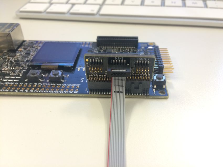
With the use of the Simplicity Debug Adapter Board plugged into these two 20-pin connectors, a 10-pin connector interface is exposed
(see mini connector in the right-hand image in the figure below), which provides a subset of debug capabilities and features in a stand-
ardized small form-factor connector. These capabilities include the following:
• SWD (Serial Wire Debug, including SWO)
• AEM (advanced energy monitoring)
• PTI (packet trace interface [WSTK only])
• VCOM (virtual COM port)
The figure below shows the Simplicity Debug Adapter Board.
Figure 5.1. Simplicity Debug Adapter Board
In order to take advantage of these capabilities and features, Silicon Labs recommends including the Mini Simplicity Connector in the
custom hardware design. Alternatively, if only serial wire / JTAG programming and debug capabilities are desired, a standard 10-pin
ARM Cortex programming interface is available through the Cortex port of the Simplicity Debug Adapter Board.
silabs.com | Building a more connected world. Rev. 0.9 | 8AN958: Debugging and Programming Interfaces for Custom Designs
Alternative Interfaces
5.1.1 Connector Pin-Out (MINI)
The figure below shows the pin-out for this 10-pin Mini Simplicity connector, while table below lists the pin functions associated with this
pin-out.
VAEM 1 2 GND
RST 3 4 VCOM_RX
VCOM_TX 5 6 SWO
SWDIO 7 8 SWCLK
PTI_FRAME 9 10 PTI_DATA
Figure 5.2. Mini Simplicity Connector Pin-Out
Table 5.1. Mini Simplicity Connector Pin Function
Pin # Pin Name Pin Function EFR32 Functionality
1 VAEM Target Advanced Energy Monitor Voltage Net VDD
2 GND Target Ground VSS
3 RST Target Reset (Active Low) RESETn
4 VCOM_RX Target Pass-through UART/Virtual COM Port Receive US0_RX
5 VCOM_TX Target Pass-through UART/Virtual COM Port Transmit US0_TX
6 SWO Target Serial Wire Output SWO
7 SWDIO Target Serial Wire Data Input/Output SWDIO
8 SWCLK Target Serial Wire Clock SWCLK
9 PTI_FRAME Target Packet Trace Interface Frame Signal FRC_DFRAME
10 PTI_DATA Target Packet Trace Interface Data Signal FRC_DOUT
Note: Mini Simplicity Connector pin-out is referenced from the device target side.
Note: The power switch on the WSTK main board determines whether the WSTK VAEM pin sources current to the target. When this
power switch is set to the “AEM” position, the WSTK is connecting VAEM to the target and monitoring current of the external target
using AEM. If the target board requires external power supply, the power switch of the WSTK should be set to the “BAT” position, dis-
connecting the on-board regulator and AEM circuits.
silabs.com | Building a more connected world. Rev. 0.9 | 9AN958: Debugging and Programming Interfaces for Custom Designs
Alternative Interfaces
5.1.2 Connector Pin-Out (Cortex)
The figure below shows the pin-out for this 10-pin standard ARM Cortex Debug Connector from the Simplicity Debug Adapter Board,
while the table below lists the pin functions associated with this pin-out.
Note: Silicon Labs deviates from the ARM standard for this connector by not including the key pin.
VTARGET 1 2 SWDIO/TMS/C2D
GND 3 4 SWCLK/TCK/C2CK
GND 5 6 SWO/TDO
KEY 7 8 NC/TDI/C2Dps
GNDDetect 9 10 nRESET/C2CKps
Figure 5.3. 10-pin Standard ARM Cortex Connector Pin-Out
Table 5.2. 10-pin Standard ARM Cortex Connector Pin Descriptions
Pin Number Pin Name
1 VTARGET
2 SWDIO/TMS/C2D
3 GND
4 SWCLK/TCK/C2CK
5 GND
6 SWO/TDO
7 KEY
8 NC/TDI/C2Dps
9 GNDDetect
10 nRESET/C2CKps
Note: Care should be taken when using the debug adapter (BRD8010A) and the cortex connector as it connects the VTARGET pin (pin
1) to the VMCU net of the WSTK in debug mode OUT. For the VTARGET pin to work as a "sensing" pin, the power switch of the WSTK
main board should be set to the "BAT" position, disconnecting the on-board regulator and AEM circuits. In this scenario, the target
board requires external power supply.
5.1.3 Connector Pin-Out (ISA3)
This interface allows a WSTK to interface with existing EM3x wireless products, which include the 10-pin Packet Trace connector foot-
print.
silabs.com | Building a more connected world. Rev. 0.9 | 10AN958: Debugging and Programming Interfaces for Custom Designs
Alternative Interfaces
5.1.4 Connector Part Numbers
The table below lists examples of connectors that can be placed on the customer design for this connector.
Table 5.3. Example Connector Part Numbers
Manufacturer Manufacturer PN Notes
Samtec FTSH-105-01-L —
Samtec FTSH-105-01-L-DV Add –K for keying shroud
Samtec FTSH-105-01-L-DH Right-angle
Samtec FTSH-105-01-L-D-K Through hole, add –K for keying shroud
Samtec FTSH-105-01-L-D-R Through hole, right-angle
5.1.5 Connector Footprint
For the recommended connector footprint, refer to the manufacturer specifications and recommendations in the applicable connector
part data sheet.
5.2 Tag-Connect™ 10-pin Interface
If the same capabilities of the of the Simplicity Debug Adapter Board interface (either through MINI or CORTEX port of the Simplicity
Debug Adapter Board) are desired but the design is space constrained, a Tag-Connect™ 10-pin interface is a possible alternative. This
interface maintains the 10-pin feature set and uses the same Simplicity Adapter Board, as noted in 5.1 Simplicity Debug Adapter Board
Interfaces. This interface also uses a different cable (either TC2050-IDC-NL-050-ALL or TC2050-ICD-050-ALL) and utilizes a smaller
footprint area on the custom target hardware board, given the lack of a connector required on the target hardware design. The NL ver-
sion has no legs, while the standard version includes legs for locking the cable into place on the PCB. For additional details on the
interface cable required for interfacing to the target hardware design for this option, see http://www.tag-connect.com/TC2050-IDC-050-
ALL or http://www.tag-connect.com/TC2050-IDC-NL-050-ALL.
Figure 5.4. TC2050-IDC-NL-050-ALL Cable Figure 5.5. TC2050-IDC-050-ALL Cable
5.2.1 Interface Pin-Out
The pin-out for this interface is identical to the ones listed in Table 5.1 Mini Simplicity Connector Pin Function on page 9 or Table
5.2 10-pin Standard ARM Cortex Connector Pin Descriptions on page 10.
silabs.com | Building a more connected world. Rev. 0.9 | 11AN958: Debugging and Programming Interfaces for Custom Designs
Alternative Interfaces
5.2.2 Interface Footprint
The footprint details for this interface on the custom target hardware board side can be found at http://www.tag-connect.com/Materials/
TC2050-IDC%20Datasheet.pdf or http://www.tag-connect.com/Materials/TC2050-IDC-NL%20Datasheet.pdf.
Note: The pinout noted in Section 5.2.1 Interface Pin-Out is one-for-one in the schematic implementation, but the PCB footprint pin
numbering generally differs from the mini-simplicity connector and between Tag-Connect part numbers. Always consult the Tag-
Connect documentation for the correct PCB footprint layout and pin numbering for the Tag-Connect part number intended.
5.3 Tag-Connect 6-pin Interface
If only a serial wire programming and debug interface is desired on the target hardware design, or space constraints prevent adding
larger interfaces, a Tag-Connect 6-pin interface is a possible solution. This interface is similar to the Tag-Connect 10-pin interface but
connects to the 20-pin Standard ARM Cortex Debug Connector directly and provides only 6-pins for serial wire debug capabilities only.
The cable part numbers are TC2030-CTX-20-NL and TC2030-CTX-20. The NL version has no legs, while the standard version include
legs for locking the cable into place on the PCB. For additional details on these cables, see http://www.tag-connect.com/TC2030-
CTX-20 and http://www.tag-connect.com/TC2030-CTX-20-NL.
Note: VTARGET is included in the 6-pin interface to provide the correct logic signal level reference from the target hardware design to
the debugger and is not a power source pin from the debugger. Because VAEM is not included on the ARM Cortex Debug Connector,
the Tag-Connect 6-pin interface assumes VDD is supplied to the target hardware design by an alternate interface.
Figure 5.6. TC2030-CTX-20-NL Cable Figure 5.7. TC2030-CTX-20 Cable
silabs.com | Building a more connected world. Rev. 0.9 | 12AN958: Debugging and Programming Interfaces for Custom Designs
Alternative Interfaces
5.3.1 Interface Pin-Out
The figure and table below show the pin-out and descriptions for this interface.
VTARGET 1 2 SWDIO
nRESET 3 4 SWCLK
GND 5 6 SWO
Figure 5.8. 6-pin Interface Pin-Out
Table 5.4. Pin Descriptions
Pin Function
1 VTARGET
2 SWDIO
3 nRESET
4 SWCLK
5 GND
6 SWO
5.3.2 Interface Footprint
The footprint details for this interface to be placed on the custom target hardware board can be found at http://www.tag-connect.com/
Materials/TC2030-IDC.pdf and http://www.tag-connect.com/Materials/TC2030-IDC-NL.pdf.
Note: The pinout noted in Section 5.3.1 Interface Pin-Out is one-for-one in the schematic implementation, but the PCB footprint pin
numbering generally differs from the mini-simplicity connector and between Tag-Connect part numbers. Always consult the Tag-Con-
nect documentation for the correct PCB footprint layout and pin numbering for the Tag-Connect part number intended.
silabs.com | Building a more connected world. Rev. 0.9 | 13AN958: Debugging and Programming Interfaces for Custom Designs
Special Considerations
6. Special Considerations
6.1 IOVDD < Main Supply Voltage
In cases where IOVDD is less than the main supply voltage on the target hardware (for example, IOVDD at 1.8 V and main supply at
3.3 V), care needs to be taken when interfacing to the STK or WSTK main board to ensure proper logic levels of the GPIO between
target and debugger.
• When both the 20-pin Simplicity Connector and ARM Cortex Debug+ETM Connector are connected to the target hardware
• IOVDD should be connected to the VTARGET net of the debug connector. The target main supply voltage net (VMCU - AVDD,
VREGVDD) should be connected to the VAEM net of the Simplicity Connector (Pin 1). This ensures that the reference voltage for
the target debug interface signals is correct. In this scenario, if supplying voltage from the WSTK main board BRD4001A with
target voltage select switch in AEM position, current measurements will be roughly 50–100 μA higher than normal due to power-
ing of the WSTK main board BRD4001A level shifters.
EXAMPLE EFR32xG1x
WSTK MAIN BOARD BRD4001A
TARGET DEVICE
VAEM 1 2 Virtual COM TX / MOSI
3V3 3 4 Virtual COM RX / MISO
5V 5 6 Virtual COM CTS / SCLK
GND 7 8 Virtual COM RTS / CS
GND 9 10 Packet Trace 0 Sync
GND 11 12 Packet Trace 0 Data
GND 13 14 Packet Trace 0 Clock
GND 15 16 Packet Trace 1 Sync
Board ID SCL 17 18 Packet Trace 1 Data
Board ID SDA 19 20 Packet Trace 1 Clock
SIMPLICITY CONNECTOR P701
VTARGET 1 2 TMS / SWDIO / C2D
GND 3 4 TCK / SWCLK / C2CK
GND 5 6 TDO / SWO
NC 7 8 TDI / C2Dps
Cable Detect 9 10 RESET / C2CKps
NC 11 12 TRACECLK
NC 13 14 TRACED0
GND 15 16 TRACED1
GND 17 18 TRACED2
GND 19 20 TRACED3
DEBUG CONNECTOR P800
silabs.com | Building a more connected world. Rev. 0.9 | 14AN958: Debugging and Programming Interfaces for Custom Designs
Special Considerations
• When using the Simplicity Debug Adapter Board BRD4001A for some of the alternative interfaces detailed in 5. Alternative Interfa-
ces
• Only the VAEM net is available and VTARGET is buffered from VAEM. In this case, the target IOVDD net needs to be connected
to the Simplicity Debug Adapter Board BRD4001A VAEM net (Pin 1) to ensure that the WSTK main board BRD4001A level shift-
ers work properly, and there will be no target main supply connection to the Simplicity Debug Adapter Board. Also, in this mode,
the target power select switch needs to be set to BAT.
EXAMPLE EFR32xG1x WSTK MAIN BOARD BRD4001A WITH
TARGET DEVICE SIMPLICITY DEBUG ADAPTER BOARD
BRD8010A
MINI SIMPLICITY CONNECTOR VAEM 1 2 GND
RST 3 4 VCOM_RX
VCOM_TX 5 6 SWO
SWDIO 7 8 SWCLK
PTI_FRAME 9 10 PTI_DATA
BRD8010A MINI CONNECTOR
Note:
1. For EFR32 series 1 devices (EFR32xG1x), the reset pin is internally pulled up to AVDD using an internal 40-43 k ohm resistor. For
EFR32 series 2 devices (EFR32xG2x), the reset pin is internally pulled up to DVDD using an internal 44k ohm resistor, and cus-
tomers should connect IOVDD and DVDD to the same supply in order to avoid unexpected debugger problems due to voltage dif-
ferences between reset pin and GPIO pins.
2. For EFR32 series 1 devices EFR32xG12 and later, the DCDC defaults to a disconnected state out of reset (rather than the bypass
mode state for EFR32xG1 devices). See AN0948 sections 3.3 and 3.4 and the EFR32xGx reference manual Energy Management
Unit (EMU) section for additional details. This is important to keep in mind for customers connecting the DCDC output to IOVDD in
that they will be unable to program the devices, as the SWD pins will be floating and unpowered. An external supply connection to
the IOVDD net would be required for initial programming in this configuration. Therefore, it is recommended to use caution when
connecting IOVDD to the DCDC output of the EFR32xG12 and later variants.
6.2 Network Co-Processor (NCP)
When the target hardware is a wireless network co-processor (NCP), care should be taken to ensure that the VCOM interface to the
WSTK debugger does not utilize the same pins selected for the NCP interface (either SPI or UART), as this may cause contention of
either the NCP operation or the VCOM serial port operation. If the VCOM interface is desired for test purposes and the same pins are
selected for the NCP interface, such as for a QFN32 package or otherwise GPIO-constrained devices, series 0 Ω resistors are recom-
mended in-line with the VCOM connection to the debugger (to be depopulated when the NCP application is running). This ensures no
contention of NCP operation when the debugger is connected to the target device. Conversely, when running test applications such as
Nodetest, RAILtest or Manufacturing Library, the Host connections to the NCP may conflict with the UART/VCOM signals, thereby not
allowing the test application to properly function. In these situations, the best method may be to route (in layout) the resistor footprints to
allow a connection between the EFR32 and the Host, or between the EFR32 and the VCOM port, depending on placement of the 0 Ω
resistor.
It is also recommended to add a 1k ohm series resistor between the NCP and Host on the NCP RESET signal.
silabs.com | Building a more connected world. Rev. 0.9 | 15AN958: Debugging and Programming Interfaces for Custom Designs
Special Considerations
6.3 3-wire SPI PTI
When utilizing a high-speed PHY like the BLE 2Mbps PHY, it is recommended that the customer use 3-wire SPI PTI rather than 2-wire
UART PTI. However, 3-wire PTI is not supported via the Mini Simplicity Interface so the Simplicity Interface needs to be used to access
the 3rd PTI pin (FRC_DCLK).
silabs.com | Building a more connected world. Rev. 0.9 | 16AN958: Debugging and Programming Interfaces for Custom Designs
Related Documentation
7. Related Documentation
AN124: Pin Sharing Techniques for the C2 Interface:
https://www.silabs.com/documents/public/application-notes/AN124.pdf
AN127: FLASH Programming via the C2 Interface:
https://www.silabs.com/documents/public/application-notes/AN127.pdf
AN105: Programming FLASH through the JTAG Interface:
https://www.silabs.com/documents/public/application-notes/an105.pdf
AN0062: Programming Internal Flash Over the Serial Wire Debug Interface:
https://www.silabs.com/documents/public/application-notes/an0062.pdf
AN1011: Standalone Programmer via the SWD Interface:
https://www.silabs.com/documents/public/application-notes/AN1011-efm32-standalone-programmer.pdf
AN136: Silicon Labs Production Programming Options:
https://www.silabs.com/documents/public/application-notes/AN136-production-programming-options.pdf
AN1222: Production Programming of Series 2 Devices:
https://www.silabs.com/documents/public/application-notes/an1222-efr32xg2x-production-programming.pdf
AN0043: EFM32 Debug and Trace:
https://www.silabs.com/documents/public/application-notes/AN0043.pdf
AN961: Bringing Up Customer Nodes for the Mighty Gecko and Flex Gecko Families:
https://www.silabs.com/documents/public/application-notes/an961-custom-nodes-efr32.pdf
UG162: Simplicity Commander Reference Guide:
https://www.silabs.com/documents/public/user-guides/ug162-simplicity-commander-reference-guide.pdf
silabs.com | Building a more connected world. Rev. 0.9 | 17AN958: Debugging and Programming Interfaces for Custom Designs
Revision History
8. Revision History
Revision 0.9
August, 2021
• Added VTARGET note to 5.1.2 Connector Pin-Out (Cortex) section.
Revision 0.8
May, 2021
• Edits to the Debug Connector Pin Descriptions Table
• Edits to the Tag-Connect 6-pin Interface section
• Edits to Special Considerations IOVDD Note section
• Edits to Special Considerations NCP section
Revision 0.7
October, 2020
• Added Device Compatibility section
• Edits to Special Considerations section to further clarify IOVDD scenario
• Added Revision History section
• Added more related documentation links
Revision 0.6
February, 2018
• Edits to Special Considerations section
Revision 0.5
November, 2017
• Edits to Special Considerations section
Revision 0.4
December, 2016
• Added Special Considerations section
Revision 0.3
July, 2016
• Title change from "Mini Simplicity Connector Interface" to "Debugging and Programming Interfaces for Custom Designs"
• Content changes to cover all STK and WSTK programming interfaces
Revision 0.2
February, 2016
• Initial public release
Revision 0.1
December, 2015
• Initial release, internal only
silabs.com | Building a more connected world. Rev. 0.9 | 18Simplicity Studio
One-click access to MCU and wireless
tools, documentation, software,
source code libraries & more. Available
for Windows, Mac and Linux!
IoT Portfolio SW/HW Quality Support & Community
www.silabs.com/IoT www.silabs.com/simplicity www.silabs.com/quality www.silabs.com/community
Disclaimer
Silicon Labs intends to provide customers with the latest, accurate, and in-depth documentation of all peripherals and modules available for system and software imple-
menters using or intending to use the Silicon Labs products. Characterization data, available modules and peripherals, memory sizes and memory addresses refer to each
specific device, and “Typical” parameters provided can and do vary in different applications. Application examples described herein are for illustrative purposes only. Silicon
Labs reserves the right to make changes without further notice to the product information, specifications, and descriptions herein, and does not give warranties as to the
accuracy or completeness of the included information. Without prior notification, Silicon Labs may update product firmware during the manufacturing process for security or
reliability reasons. Such changes will not alter the specifications or the performance of the product. Silicon Labs shall have no liability for the consequences of use of the infor-
mation supplied in this document. This document does not imply or expressly grant any license to design or fabricate any integrated circuits. The products are not designed or
authorized to be used within any FDA Class III devices, applications for which FDA premarket approval is required or Life Support Systems without the specific written consent
of Silicon Labs. A “Life Support System” is any product or system intended to support or sustain life and/or health, which, if it fails, can be reasonably expected to result in
significant personal injury or death. Silicon Labs products are not designed or authorized for military applications. Silicon Labs products shall under no circumstances be used
in weapons of mass destruction including (but not limited to) nuclear, biological or chemical weapons, or missiles capable of delivering such weapons. Silicon Labs disclaims
all express and implied warranties and shall not be responsible or liable for any injuries or damages related to use of a Silicon Labs product in such unauthorized applications.
Note: This content may contain offensive terminology that is now obsolete. Silicon Labs is replacing these terms with inclusive language wherever possible. For more
information, visit www.silabs.com/about-us/inclusive-lexicon-project
Trademark Information
Silicon Laboratories Inc. ® , Silicon Laboratories ® , Silicon Labs ® , SiLabs ® and the Silicon Labs logo ® , Bluegiga ® , Bluegiga Logo ® , Clockbuilder® , CMEMS ® , DSPLL ® , EFM ® , EFM32 ® ,
EFR, Ember® , Energy Micro, Energy Micro logo and combinations thereof, “the world’s most energy friendly microcontrollers”, Ember® , EZLink ® , EZRadio ® , EZRadioPRO ® , Gecko ® ,
Gecko OS, Gecko OS Studio, ISOmodem ® , Precision32 ® , ProSLIC ® , Simplicity Studio ® , SiPHY® , Telegesis, the Telegesis Logo ® , USBXpress ® , Zentri, the Zentri logo and Zentri DMS,
Z-Wave ® , and others are trademarks or registered trademarks of Silicon Labs. ARM, CORTEX, Cortex-M3 and THUMB are trademarks or registered trademarks of ARM Hold-
ings. Keil is a registered trademark of ARM Limited. Wi-Fi is a registered trademark of the Wi-Fi Alliance. All other products or brand names mentioned herein are trademarks
of their respective holders.
Silicon Laboratories Inc.
400 West Cesar Chavez
Austin, TX 78701
USA
www.silabs.comYou can also read