Automated Catheter Tip Repositioning for Intra-cardiac Echocardiography - arXiv
←
→
Page content transcription
If your browser does not render page correctly, please read the page content below

Springer Nature 2021 LATEX template

                                              Automated Catheter Tip Repositioning for
                                                  Intra-cardiac Echocardiography
arXiv:2201.08889v1 [cs.RO] 21 Jan 2022

                                              Young-Ho Kim1*, Jarrod Collins1 , Zhongyu Li2 , Ponraj Chinnadurai3 , Ankur
                                                          Kapoor1 , C. Huie Lin2,4 and Tommaso Mansi1
                                                 1
                                                  Siemens Healthineers, Digital Technology & Innovation, Princeton, NJ, USA.
                                                          2
                                                            Houston Methodist Research Institute, Houston, TX, USA.
                                                   3
                                                     Siemens Medical Solutions Inc., Advanced Therapies, Malvern, PA, USA.
                                                  4
                                                    Houston Methodist DeBakey Heart & Vascular Center, Houston, TX, USA .

                                                                                     Abstract
                                               Purpose: Intra-Cardiac Echocardiography (ICE) is a powerful imaging modality for
                                               guiding cardiac electrophysiology and structural heart interventions. ICE provides
                                               real-time observation of anatomy and devices, while enabling direct monitoring of
                                               potential complications. In single operator settings, the physician needs to switch
                                               back-and-forth between the ICE catheter and therapy device, making continuous
                                               ICE support impossible. Two operators setup are therefore sometimes implemented,
                                               with the challenge of increase room occupation and cost. Two operator setups
                                               are sometimes implemented, but increase procedural costs and room occupation.
                                               Methods:      ICE catheter robotic control system is developed with auto-
                                               mated catheter tip repositioning (i.e. view recovery) method, which can
                                               reproduce important views previously navigated to and saved by the
                                               user. The performance of the proposed method is demonstrated and
                                               evaluated in a combination of heart phantom and animal experiments.
                                               Results: Automated ICE view recovery achieved catheter tip position accu-
                                               racy of 2.09 ± 0.90 mm and catheter image orientation accuracy of
                                               3.93 ± 2.07◦ in animal studies, and 0.67 ± 0.79 mm and 0.37 ± 0.19◦
                                               in heart phantom studies, respectively. Our proposed method is also success-
                                               fully used during transeptal puncture in animals without complications, show-
                                               ing the possibility for fluoro-less transeptal puncture with ICE catheter robot.
                                               Conclusion: Robotic ICE imaging has the potential to provide precise and
                                               reproducible anatomical views, which can reduce overall execution time, labor
                                               burden of procedures, and x-ray usage for a range of cardiac procedures.

                                               Keywords: Automated View Recovery, Path Planning, Intra-cardiac echocardiography (ICE),
                                               Catheter, Tendon-driven manipulator, Cardiac Imaging

                                         1 Introduction
                                         Interventional cardiology has expanded its role dramatically in recent years to now
                                         encompass treatment of many disease states which were once considered to only have
                                         surgical options. This growth has been significantly motivated by the introduction of
                                         new treatment devices and advances in intraoperative imaging modalities. Intra-cardiac
                                         echocardiography (ICE) has been evolving as a real-time imaging modality for guid-
                                         ing interventional procedures in electrophysiology [1, 2], congenital [3, 4], and structural
                                         heart interventions [5], among others. When compared to another more established real-
                                         time imaging modality, transesophageal echocardiography (TEE), ICE has improved
                                         patient tolerance by not requiring esophageal intubation, requires only local anesthesia

                                                                                          1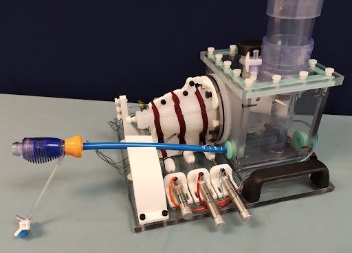
Springer Nature 2021 LATEX template

2     Automated Catheter Tip Repositioning for Intra-cardiac Echocardiography

with conscious sedation, can be operated by the interventionalist, and does not interfere
with fluoroscopic imaging [6]. Real-time ICE imaging has an expanding role in providing
uninterrupted guidance for valve replacement interventions [7, 8], left atrial appendage
closure [9, 10], septal defect closure [11], and catheter-based ablation for cardiac arrhyth-
mia [12]. However, with the increased reliance on imaging to perform these complex
procedures, there is a high cognitive demand on physicians, who may now be performing
both the interventional task and simultaneously acquiring the guiding images. Moreover,
they are not always experts in reading ultrasound and navigating these images, which
makes ICE handling even more difficult.
    ICE imaging requires substantial training and experience to become comfortable
with steering the catheter from within the cardiac anatomy, which hinders its adoption as
standard of care [4, 7]. In practice, the interventionalist needs to continuously manipulate
several catheters throughout the procedure, each having different control mechanisms.
For example, a typical ablation treatment for cardiac arrhythmia can require tens to hun-
dreds of individual ablations at very specific locations. ICE imaging can be beneficial
to monitor for developing complications, target anatomy, facilitate adequate tissue con-
tact, and monitor lesion development during ablations [13]. However, this can quickly
become a tedious procedure if repositioning are frequently needed. Similarly in struc-
tural heart procedures, clinicians can manipulate the ICE catheter to localize and measure
the area of treatment and then either park (e.g. to watch for complications) or retract
the ICE imaging catheter while devices are deployed under fluoroscopic guidance. The
ICE catheter is then relocated to visually confirm the placement of therapeutic devices.
This manner of repeated manipulation throughout the course of treatment is common for
interventions across disciplines but requires intensive coordination, spatial understand-
ing, and manual dexterity that can lead to fatigue in longer or more difficult procedures
and imposes a significant learning curve for new users.
    When considering these limitations, it is reasonable that a robotic-assist system that
can hold and actively manipulate the ICE catheter, either through operator input or semi-
autonomous processes, could ease the workload of the physician during treatment and
potentially enable the use of ICE for novel and more complex tasks. Several commercial
robotic systems for less specific catheter manipulation are currently marketed, including
Amigo RCS (Catheter Precision, Inc., Mount Olive, NJ, USA), CorPath GRX (Corindus
Inc., Waltham, MA), Magellan, and Sensei (Hansen Medical Inc., Mountain View, CA,
USA). One commercially-available robotic system for ICE catheter manipulation is the
Sterotaxis V-Sono system [14], which controls the ICE catheter robotically, but with
reduced degrees-of-freedom. This system provides robotic control of devices via human
operators at a remote cockpit based on streamed real-time image (e.g. fluoroscopic) feed-
back. Loschak et al. [15] have presented a research prototype robotic ICE manipulator
and provide a method using electromagnetic (EM) tracking systems to actively maintain
focus within the field of view. While some ICE catheters are now manufactured with an
EM sensor in the tip for application in ablation procedures, there is an accompanying
increase in cost, which is a major consideration for a single-use device. In practice, many
commercially available ICE catheters are single use with no position-tracking sensors
installed. Therefore, the controller for such a robotic-assist system requires an open-
loop where spatial feedback are not continuously available. Accordingly, with this work
we introduce a robotic ICE catheter controller that operates without discrete position
Springer Nature 2021 LATEX template

        Automated Catheter Tip Repositioning for Intra-cardiac Echocardiography                                  3

Fig. 1 Overview of the experimental setting, the proposed robotic ICE manipulator, and control scheme: (a)(b)
The pig is placed in supine recumbency. The ICE catheter is introduced to the femoral vein at the groin through
an introducer sheath by manually, and attached to the ICE manipulator consisted of the proximal/distal units.
The joystick input can direct the robotic manipulator. First, the physician-operator manipulates the ICE catheter
while surveying images via the ultrasound machine and saving desired views using joystick buttons. Then,
whenever the operator request one of the saved views during the procedures, the automated view recovery
module can reproduce important views that have been previously saved by the user during the first ICE survey
procedure. (c) ICE catheter robot monitoring system shows the list of saved views and lets the operator know
the current state of view recovery module (e.g., idle, search phase, execution phase, and completed states). (d)
Diagram of view recovery process: First, a roadmap that traces motor state configurations is generated while
the operator manipulates the ICE catheter by joystic input with each unique configuration represented by a
white dot and connected to neighboring configurations by an edge element. Second, a library of desired views
is generated by labeling certain states within this roadmap. The colored dots (i.e., green, red, yellow, and purple
dots) represents the bookmarked or saved state of the robot. Lastly, when the user specify the desired view in
the library of views, then the robotic controller can return to any of these views by retracing a path along the
roadmap from the current state to the desired state.

feedback from added sensors. We believe that this is the first work that demonstrates
an automated function for repositioning ICE imaging during a common procedure in
animal.
    In this paper, we introduce a new robotic controller that can simplify ICE catheter
manipulation. Figure 1 presents an overview of the proposed robotic-assist system. As
a first step towards automation in clinical ICE workflows, we propose a view recov-
ery method which can autonomously reproduce important views previously navigated
to and saved by the user (Section 2). To achieve this, we implement methods to incre-
mentally generate a topological roadmap of the robotic motor states. When queried, the
method provides a path to the specified view by retracing along previous motor con-
figurations and can be reproduced at any time during the procedure. We evaluate our
proposed method in a combination of phantom and animal experiments, also during two
fluoro-less robot-guided transseptal punctures in animal (Section 3).

2 Materials and Methods
2.1 ICE catheter robot (ICEbot)
The ICE catheter (ACUSON AcuNav Volume ICE catheter, Siemens Healthineers) is
shown in Figure 2 with two knobs, bending section, and ultrasound array labeled. Two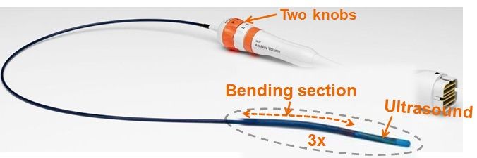
Springer Nature 2021 LATEX template

4     Automated Catheter Tip Repositioning for Intra-cardiac Echocardiography

pairs of tendon-driven pull mechanisms (one is Anterior-Posterior, nother is Right-Left)
consist of a hollow polymer as a sheath and a thread sliding inside the sheath acting as
a tendon. Each pair is bound to a common knob, which can pull an individual thread by
rotating the knob, allowing one thread to be pulled while the other remains passive. The
ultrasound array is located at the tip in the center of the two pairs of tendon mechanisms.
     We developed an ICE catheter robotic control sys-
tem to manipulate the off-the-shelf ICE catheter (i.e.
ACUSON AcuNav Volume ICE catheter family). Our
robot manipulator consists of two components as shown
                                                                Fig. 2 ACUSON AcuNav Vol-
in Figure 1(b): 1) A “proximal” component holds the ume ICE catheter, Source: Siemens
catheter shaft, sits directly outside of the introducer Healthineers
sheath, and contributes linear and rotational motion of the catheter. 2) A “distal” compo-
nent holds the catheter handle and controls the two knobs for the bending of the catheter
tip, and bulk rotation of the catheter. Moreover, this bulk rotation is synchronized with
the proximal.
     The robot has 4 degrees of freedom. Without loss of generality, we follow the same
nomenclature in [15]: two DOFs for steering the catheter tip in two planes (anterior-
posterior knob angle φ1 and right-left knob angle φ2 ) using two knobs on the catheter
handle, bulk rotation φ3 , and translation d4 along the major axis of the catheter. We define
the robot’s configuration, q = (φ1 , φ2 , φ3 , d4 ) in R4 . The robot can be controlled with
an external joystick (3Dconnexion SpaceMouse pro providing 6DoF analog stick with
multiple buttons), which provides a digital input that is directly mapped to the standard
knob controls of the catheter or a more intuitive control scheme where the users inputs
are directly applied at the catheter tip coordinate frame.

2.2 Automated View Recovery: a topological map construction and
    path planning
Automated view recovery module is used to reproduce important views that have been
previously saved by the user, so that the repeated ICE repositioning operations for
physicians can be significantly reduced leading the user to focus on the main device
handling. The exemplary scenario is following: during an ICE survey for the procedure,
the physician-operator continuously manipulates ICE catheter for target anatomies, then
the operator picks and saves views using joystick buttons, which is believed as desired
views for visually confirming therapeutic devices later. During this process, our proposed
module continuously constructs a topological graph (“a roadmap”) when the operator
manipulates the ICE catheter by joystick input to the robotic manipulator, and generates
a library of views (i.e. important locations on the roadmap that will be revisited later)
when the operator clicked the joystick buttons. Once a roadmap and a library of views
are constructed by the operator, then the operator can query for a specific view anytime
during the procedure. The requested views among a library of views will be given to the
controller to search a path from the current pose to the target pose, and then the controller
executes motions.
    Figure 1(c) shows the summary illustration of automated view recovery. Let G(V, E)
represent a graph in which V denotes the set of configurations qi and E is the set of
paths (qi , qj ). Our proposed automated view recover module is divided into two phases:
Construction phase and Query phase.
Springer Nature 2021 LATEX template
Automated Catheter Tip Repositioning for Intra-cardiac Echocardiography 5
Algorithm 1 BUILD ROADMAP VIEWS (qn , G , V , )
1: INPUT: the current configuration qn , the current roadmap G , the current library of
views V , the density parameter
2: OUTPUT: G , V
3: Initialize: qbefore = [ ], G = [ ], V = [ ]
4: while ROBOT is OPERATIONAL do
5: qn is updated from the current configuration
6: if qbefore 6= qn then
7: for each qi ∈ NEIGHBORHOOD(qn ,G ) do
8: if dist(qi , qn ) ≤ then
9: if qn ∈/ G then
10: G .add vertex(qn )
11: end if
12: G .add edge(qi ,qn )
13: end if
14: end for
15: if VIEW SAVING FLAG then
16: V .pushback(qn )
17: end if
18: qbefore = qn
19: end if
20: end while
Construction phase: The library of views and roadmap generation phase: as the robot
moves by the operator, the current configuration qn is updated. If qn is not the same
as the previous configuration qbef ore , then the algorithm inserts qn as new vertex of G ,
and connect pairs of qn and existing vertices if the distance is less than a density param-
eter (lines 10- 12 of Algorithm 1). We apply based on Euclidean distance (assuming
1 mm ≡ 1◦ ). If a larger (default = 1) were applied, then the search would be faster,
however a safety of the path would not be guaranteed, as larger steps along the path
could result in collision with anatomy. To validate our approach in this paper, we used
= 1, so generated paths have a millimeter/degree resolution. Concurrent with roadmap
generation, the algorithm constructs a library of views V when the user saves the view
anytime, where V = (q01 , ..., q0m ), q0 is the user saved configuration. m is the number of
the user saved views. This step is shown in line 16 of Algorithm 1.
Query phase: Given a start configuration qS (the current qn ) and a goal configuration
qG ∈ V , is given during the procedures. Since each configuration is already in G , we use
a discrete A∗ search algorithm to obtain a sequence of edges that forms a path from qS
to qG . The more detailed roadmap construction and search algorithms in the graph are
in [16].
3 Experiments and Results
3.1 Experimental and Validation design
3.1.1 Heart phantom studySpringer Nature 2021 LATEX template
6 Automated Catheter Tip Repositioning for Intra-cardiac Echocardiography
Initial validation of the robotic catheter control during view
recovery was performed with the catheter tip inserted into the
left ventricle of a custom beating heart phantom (shown in
Figure 3, Archetype Medical) for ICE and TEE valve imaging.
An EM sensor (Model 800 sensor, 3D Guidance, Northern Dig-
ital Inc.) was attached to the catheter tip to provide real-time
Fig. 3 A custom beating
tracking as the catheter was manipulated by robotic control. heart phantom
This data provides the discrete 3D coordinate and orientation of the catheter tip as
it is manipulated when testing the view recovery process. Then, catheter tip position
error was calculated as the Euclidean distance between each catheter tip location during
view recovery and the respective initial catheter tip location. Similarly, the orientation of
the catheter tip is provided by the EM-sensor throughout testing, and the ICE catheter
orientation error was calculated.
3.1.2 Animal study
Four animal validation experiments were performed at the Houston Methodist Institute
for Technology, Innovation & Education (MITIE, Houston Methodist Hospital) with
in vivo study protocol approved by the Institutional Animal Care and Use Committee
(IACUC). All testing of the robotic catheter controller was performed under general
anesthesia. Vascular access was achieved bilaterally to allow for manipulation of ICE and
other device or monitoring catheters. In vivo experimental setup is pictured in Figure 1.
In each experiment, the ICE catheter, with robotic controller pre-attached, was intro-
duced to the venous system through an introducer sheath with balloon seal (DrySeal Flex
Introducer Sheath, Gore) before being manually advanced to the junction of the infe-
rior vena cava (IVC) and right atrium (RA) under simultaneous ICE and fluoroscopic
guidance.
In each experiment, initial ultrasound views of the Aortic, Mitral, and Tricuspid valve
(i.e. anatomical targets) were manipulated to and saved (i.e. as points-of-interest within
the view recovery roadmap) by one physician using joystick input to the robotic con-
troller. Views were then automatically returned to in series several times by the view
recovery process. The typical sequence was to consecutively cycle from Tricuspid Valve
to Aortic Valve to Mitral Valve in repetition (averaging 4.75 automated positioning
events to each valve per experiment).
In total, four animal experiments were performed to evaluate view recovery result-
ing in 45 total view recovery tests. In each view recovery test, following automated
robotic motion to the target view, ultrasound and volumetric images were acquired.
These data were then compared to measure the reproducibility of robot controlled
catheter tip motions. Dynamic computed tomography (DCT) images were acquired in
three of the experiments (30 out of 45) on an Artis zeego (Siemens Healthineers) to
provide volumetric ground-truth catheter position within the heart (200◦ total rotation,
5 second acquisition, 50 frames-per-second). Additionally, traditional gated computed
tomography (CT) images (15 out of 45) were acquired in the last experiments on a
SOMATOM Force (Siemens Healthineers) to provide volumetric ground-truth catheter
position within the heart (0.81 x 0.81 x 0.5 mm voxel spacing). Two-dimensional and
volumetric ultrasound imaging was acquired with an ACUSON AcuNav Volume ICE
catheter (Siemens Healthineers) in all experiments. Ultrasound images were recorded for
several heart cycles (typically 3 second acquisition).Springer Nature 2021 LATEX template
Automated Catheter Tip Repositioning for Intra-cardiac Echocardiography 7
To validate performance of a tip pose at each view, we compare catheter tip location
across multiple robotic positioning events to image targets as the primary spatial vali-
dation approach. To measure in vivo, 3D models of the ground-truth observation of the
ICE catheter when viewing a target were generated following an intensity-based thresh-
old segmentation of the intra-procedural volumetric imaging (i.e. DCT or CT) using
ITK-SNAP [17]. Co-registration between corresponding volumetric images from a sin-
gle experiment was not necessary to align the sequential imaging scans from a given
procedure as no large bulk motion (i.e., motion of the subject’s body relative to the table)
was observed between scans. Next, the ICE catheter tip was manually labeled from each
model and the centroid taken to define the discrete tip location for a given view recovery.
For visualization purposes, a curve was then fit to each catheter, constrained to terminate
at the predefined catheter tip, by fitting a fifth-order polynomial. This process provided a
discrete spatial representation of the catheter tip and body. Finally, catheter tip position
error was calculated as the Euclidean distance between each catheter tip location and the
respective initial catheter tip location (i.e., from the first viewing of the target by the user
with joystick controls) for each image target.
Further, to properly validate the change in catheter heading (i.e. imager orientation),
we use a subset of the experimental data from the final animal study (i.e. 15 samples of
CT and ultrasound images). This is because DCT was not accurate enough to distinguish
the imager orientation relative to anatomical targets. Thus, this validation of orientation
is accomplished in the final animal study by co-registering the volumetric ultrasound data
with the corresponding CT images for a given view recovery. To achieve, correspond-
ing anatomy were labeled in both the volumetric ultrasound and CT data (e.g., aortic
valve, mitral valve, and tricuspid valve) and the centroid taken. The ultrasound transducer
location (i.e. from the ICE catheter) is also known in each image space. A correspond-
ing point-based registration was then performed with the transducer and anatomies
equally weighted. Corresponding points were selected and labeled (i.e., fiducials) within
each image-space (e.g., ICE catheter tip, tricuspid valve centroid, etc). Co-registration
was achieved by performing a rigid-body, corresponding point-based alignment by the
minimization of the sum of squares of fiducial registration errors [18, 19]. Since the ultra-
sound orientation is trivial to determine in the ultrasound image space, it can then be
transformed to the CT image space. Finally, the transducer orientation error, α, was cal-
culated between each catheter orientation and the respective initial catheter orientation
for each image target by equation (1).
â · b̂
cos(α) = . (1)
kâk · kb̂k
For the volumetric ultrasound data, each anatomy was manually labeled 5 times per
acquisition and the average taken (i.e. resulting in 25 samples per target valve, 75
total samples). Intra-observer variability was measured as 1.64 ± 1.15 mm in labeling
anatomy which translates to 1.95 ± 1.55◦ error in calculation of the orientation.
3.2 Results
3.2.1 Heart phantom study results
Four unique catheter positions were manipulated to within the beating heart phantom by
joystick input to the robotic controller and saved for automated recovery. The set of target
positions encompassed manipulation of each of the 4-DoF of catheter motion. The con-
troller was then tasked with cycling the ICE catheter tip between each target position inSpringer Nature 2021 LATEX template
8 Automated Catheter Tip Repositioning for Intra-cardiac Echocardiography
Fig. 4 Longitudinal aortic valve images from each of the four experiments reported in this study. Each row
represents a separate experiment. The left-most column represents the initial viewing of the valve. Moving
right-ward each further column represents subsequent returns to the view at the annotated times.
Catheter tip position error [mm] Imager orientation error [◦ ]
Aortic Valve 2.19 ± 0.91 3.08 ± 2.49
Mitral Valve 1.71 ± 0.74 4.87 ± 2.09
Tricuspid Valve 2.38 ± 0.96 3.85 ± 1.70
Table 1 Catheter tip position (45 samples) and orientation error (15 samples): Mean and standard deviation
are across four experiments. All are measured relative to initial viewing
series a total of 16 times. Accuracy of the robotic controller was measured by an EM sen-
sor attached at the catheter tip. The set of target positions encompassed manipulation of
all 4 DOF of catheter motion. Under these conditions, the robotic controller maneuvered
the catheter tip to the target position with an average position error of 0.67 ± 0.79 mm
and rotational error of 0.37 ± 0.19◦ .
3.2.2 Animal study results
Catheter tip localization and catheter orientation error are presented in Table 1 for each
imaging target. Across all experimental data and image-targets, average catheter tip
localization error relative to the respective initial target viewing was 2.09 ± 0.90 mm (n
= 45). Further, average catheter orientation error relative to the initial target viewing was
3.93 ± 2.07◦ (n = 15). A subset of longitudinal aortic valve images from each experi-
ment are presented in Figure 4 for qualitative evaluation – with each row representing a
separate animal experiment, the first column presenting the initial viewing of the aortic
valve, and subsequent columns presenting automated recoveries of the aortic valve at the
given times. Figure 5 displays the ground-truth positioning of each ICE catheter relative
to the aorta (i.e. from contrast-enhanced gated CT). Corresponding ICE catheter orien-
tations are displayed (i.e. from co-registering volumetric ultrasound and CT) as well as
the resulting ultrasound images.
Transeptal puncture is routinely performed in electrophysiology and structural heart
procedures. With the initial development of ICE imaging in the previous two decades,
ICE-guided (i.e. zero-fluoroscopy) transeptal procedures were hypothesized. However,
to date, fluoroscopy remains the imaging modality of choice for guiding transseptalSpringer Nature 2021 LATEX template
Automated Catheter Tip Repositioning for Intra-cardiac Echocardiography 9
Fig. 5 (Left) Three-dimensional representation of aortic anatomy (red) and each of 5 ICE catheters as they
image the aortic valve when testing the view recovery process in vivo. ICE catheter orientation is represented
by the corresponding dotted lines. (Right) Ultrasound images corresponding to each ICE catheter. Where A
represents the initial viewing of the Aortic Valve and B-D represent images after applying view recovery to
return from within the heart to this view. The time of each image relative to the initial viewing of the target (A)
are noted.
Fig. 6 Application of transeptal puncture procedure: (A) Saved view 1, superior vena cava view prior to punc-
ture. Sheath is visible in right atrium abutting the septal wall. (B) Saved view 2, septal view prior to puncture.
(C) Saved view 2, septal view post puncture. Sheath has been placed through the puncture across the septal wall.
autonomous view recovery was used to manipulate ICE catheter between the two pre-saved views as needed.
therapies. Robotic ICE guidance using automated view recovery was performend for a
transeptal puncture in two animals. The physician-operator began by pre-saving two ICE
views from the RA relevant to the procedure (Figure 6 A and B). The puncture was
achieved with a Versacross RF (Baylis Medical). The procedure was performed entirely
with robotic ICE guidance (i.e. no fluoroscopy or other real-time imaging). After pre-
saving of the two guiding views, the operator did not need to maneuver the ICE via
joystick or manually for the remainder of the procedure. Automated view recovery was
utilized to manipulate between the two pre-saved views as needed (with 5 transitions
from view-to-view in each experiment). Real-time ICE view swapping was achieved
by button-press when desired. Following the procedure, the puncture was verified first
by bubble study and then by placing a sheath across the septal wall and acquiring a
CT with the left heart contrast-enhanced via the septal sheath. The detailed results are
recently presented in clinical society [20], showing that transeptal puncture was suc-
cessfully achieved without complications, and automatic view recovery of ICE robotic
manipulator might be a useful tool for ICE clinical applications.Springer Nature 2021 LATEX template
10 Automated Catheter Tip Repositioning for Intra-cardiac Echocardiography
4 Discussion
In practice, standardized anatomical imaging views are emerging as indications for ICE
continue to expand across disciplines. Enriquez et al. [21] detail standard imaging views
for a variety of structural and electrophysiology procedures. Similarly, early identifica-
tion and unobstructed monitoring of potentially life-threatening complications is one of
the most valuable functions that ICE provides [12] and is leading to its adoption as a
primary imaging modality for certain procedures, especially those involving transseptal
puncture for left heart catheterization [6].
Relative to typical right atrial measurements from echocardiography (3.6 ± 0.1 cm
and 4.2±0.1 cm for short- and long axis respectively [22]), the level of catheter tip place-
ment error (i.e. 2.1 ± 0.9 mm) and imager orientation error (i.e. 3.9 ± 2.1◦ ) observed in
this study demonstrate high accuracy for automated view recovery. These results are fur-
ther corroborated by the phantom catheter tip localization results acquired by EM sensing
(i.e. 0.67 mm and 0.37◦ ). However, we must note that the measurements taken in phan-
tom are below the reported accuracy for localization (i.e. 1.4 mm) and orientation (i.e.
0.5◦ ) and should be considered as such. Comparing these in vivo and phantom results
demonstrates a compounding of error sources when moving between experimental set-
tings which include: mechanical coupling of the catheter, robot, and sheath; interactions
between the catheter and vascular anatomy; and physiological sources such as cardiac
or respiratory motion. Altogether, we believe that these results support our conclusion
that the robotic controller and automated view recovery process introduced in this study
can accurately position the ICE catheter within the RA and reproducibly image cardiac
structures of clinical relevance.
Safety is a major concern when considering any degree of robotic autonomy in
human interfacing applications. As described, the automated view recovery method is
not autonomously finding views in an active manner, but rather relying on the user’s
initialization of each desired view and their tracing of possible paths (i.e. roadmap G ).
Thus a safe navigation highly relies on the user’s initial controls. Then, how can we gen-
erate a reliable tracing during the manual operation to gather tracing and a library of
views? First, the user may cause the catheter to contact critical anatomies (e.g. septal
wall, valves). However this might be acceptable because the ICE catheter’s end portion
and tip are designed to be yielding so that the catheter will not puncture or damage tis-
sue. Second, physicians continuously watch the ICE images while they manipulate ICE
catheters to survey anatomy. Therefore, real-time ICE image feedback helps to guide
the user during manipulation, creating a safe path. In addition, the critical safety issues
can be handled by robotic manipulation too. For example, risky actions might be easily
detected and banned by force controls. Once we have a reliable tracing and the library of
views, then with our presented semi-autonomous functionality we can recover the user’s
previous navigation including uncertainties (i.e. interaction with vessel and heart beat-
ing). Finally, our spatial- and image-based performance results support that the robotic
controller can maintain a certain accuracy accordance with the expert user’s trace.
In each animal study, we saved around 8000 states in the graph, which is about 40
min to 1 hour worth of operations. There are not many crossover nodes in constructed
graph, thus the path search time using A∗ algorithms was less than one second in our
laptop setting (Alienware m15, 9th Intel i7, 32GB memory). If the size of the graph
increased, this might not be in real-time operation. These optimization of graph searchSpringer Nature 2021 LATEX template
Automated Catheter Tip Repositioning for Intra-cardiac Echocardiography 11
is not covered in this paper. Instead, we focused on the feasibility studies for automated
view recovery.
5 Conclusion
Intra-cardiac Echocardiography (ICE) is a powerful imaging modality for guiding elec-
trophysiology and structural heart interventions. ICE provides real-time observation of
anatomy, catheters, and emergent complications. However, this increased reliance on
intraprocedural imaging creates a high cognitive demand on physicians who can often
serve as interventionalist and imager. Therefore, we developed automated view recovery
for ICE catheter robot to assist physicians with imaging and serve as a platform for devel-
oping processes for procedural automation. The automated view recovery method allows
physicians to save views during intervention and automatically return with the push of a
button. The proposed method was validated by repeated catheter positioning in cardiac
phantom with EM-sensor and animal experiments with image-based analysis. Results
support that a robotic manipulator for ICE can provide an efficient and reproducible tool,
potentially reducing execution time and promoting greater utilization of ICE imaging.
This work contributes to advancement in the application of ICE in electrophysiology and
structural heart procedures.
Disclaimer
The concepts and information presented in this paper are based on research results that
are not commercially available. Future availability cannot be guaranteed.
References
[1] L. Epstein, T. Smith, and H. TenHoff, “Nonfluoroscopic transseptal catheterization: safety
and efficacy of intracardiac echocardiographic guidance,” Journal of Cardiovascular Elec-
trophysiology, vol. 9, no. 6, pp. 625–630, 1998.
[2] L. Calo, F. Lamberti, M. Loricchio, M. D’Alto, A. Castro, A. Boggi, and et al., “Intracardiac
echocardiography: from electroanatomic correlation to clinical application in interventional
electrophysiology,” Italian Heart Journal, vol. 3, no. 7, pp. 387–398, 2002.
[3] G. Rigatelli, “Expanding the use of intracardiac echocardiography in congenital heart disease
catheter-based interventions,” Journal of the American Society of Echocardiography, vol. 18,
pp. 1230–1231, 2005.
[4] W. Tan and J. Aboulhosn, “Echocardiographic guidance of interventions in adults with con-
genital heart defects,” Cardiovascular Diagnosis and Therapy, vol. 9, no. 2, pp. S346–S359,
2019.
[5] C. Basman, Y. Parmar, and I. Kronzon, “Intracardiac echocardiography for structural heart
and electrophysiological interventions,” Current Cardiology Reports, vol. 19, no. 10, p. 102,
2017.
[6] F. Silvestry, R. Kerber, M. Brook, J. Carroll, K. Eberman, S. Goldstein, and et al.,
“Echocardiography-guided interventions,” Journal of the American Society of Echocardiog-
raphy, vol. 22, no. 3, pp. 213–231, 2009.
[7] T. Bartel, A. Edris, C. Velik-Salchner, and S. Muller, “Intracardiac echocardiography for
guidance of transcatheter aortic valve implantation under monitored sedation: a solution to a
dilemma?” European Heart Journal of Cardiovascular Imaging, vol. 17, no. 1, pp. 1–8, 2016.Springer Nature 2021 LATEX template
12 Automated Catheter Tip Repositioning for Intra-cardiac Echocardiography
[8] M. Saji, A. Rossi, G. Ailawadi, J. Dent, M. Ragosta, and D. Lim, “Adjunctive intracar-
diac echocardiography imaging from the left ventricle to guide percutaneous mitral valve
repair with the mitraclip in patients with failed prior surgical rings,” Catheterization and
Cardiovascular Interventions, vol. 87, no. 2, pp. e75–e82, 2016.
[9] J. Ren, F. Marchlinksy, G. Supple, M. Hutchinson, F. Garcia, M. Riley, and et al., “Intrac-
ardiac echocardiographic diagnosis of thrombus formation in the left atrial appendage: a
complementary role to transesophageal echocardiography,” Echocardiography, vol. 30, pp.
72–80, 2013.
[10] Y. Matsuo, P. Neuzil, J. Petru, M. Chovanec, M. Janotka, S. Choudry, and et al., “Left atrial
appendage closure under intracardiac echocardiographic guidance: feasibility and compar-
ison with transesophageal echocardiography,” Journal of the American Heart Association,
vol. 5, no. 10, p. 4, 2016.
[11] B. Medford, N. Taggart, A. Cabalka, F. Cetta, G. Reeder, D. Hagler, and et al., “Intracardiac
echocardiography during atrial septal defect and patent foramen ovale device closure in pedi-
atric and adolescent patients,” Journal of the American Society of Echocardiography, vol. 27,
no. 9, pp. 984–990, 2014.
[12] D. Filgueiras-Rama, F. de Torres-Alba, S. Castrejon-Castrejon, A. Estrada, J. Figueroa,
O. Salvador-Montanes, and et al., “Utility of intracardiac echocardiography for catheter
ablation of complex cardiac arrhythmias in a medium-volume training center,” Echocardiog-
raphy, vol. 32, no. 4, pp. 660–670, 2015.
[13] W. Saliba and J. Thomas, “Intracardiac echocardiography during catheter ablation of atrial
fibrillation,” Europace, vol. 10, no. 3, pp. 42–47, 2008.
[14] Stereotaxis, “Stereotaxis v-drive robotic navigation system,” Feb. 2020,
http://www.stereotaxis.com/products/vdrive.
[15] P. M. Loschak, L. J. Brattain, and R. D. Howe, “Algorithms for automatically pointing ultra-
sound imaging catheters,” IEEE Transactions on Robotics, vol. 33, no. 1, pp. 81–91, Feb
2017.
[16] S. M. LaValle, Planning Algorithms. New York, NY, USA: Cambridge University Press,
2006.
[17] P. A. Yushkevich, J. Piven, H. Cody Hazlett, R. Gimpel Smith, S. Ho, J. C. Gee, and
G. Gerig, “User-guided 3D active contour segmentation of anatomical structures: Signif-
icantly improved efficiency and reliability,” Neuroimage, vol. 31, no. 3, pp. 1116–1128,
2006.
[18] P. H. Schönemann, “A generalized solution of the orthogonal procrustes problem,” Psychome-
trika, vol. 31, pp. 1–10, 1966.
[19] J. Fitzpatrick, J. West, and C. Maurer, “Predicting error in rigid-body point-based registra-
tion,” IEEE Transactions on Medical Imaging, vol. 17, no. 5, pp. 694–702, 1998.
[20] Z. Li, J. Collins, Y.-H. Kim, P. Chinnadurai, T. Mansi, and C. H. Lin, “Zero-fluoroscopy
transseptal puncture guided by intelligent intracardiac echocardiography robotics,” Journal
of the American College of Cardiology, vol. 77, no. 18 Supplement 1, pp. 970–970, 2021.
[21] A. Enriquez, L. C. Saenz, R. Rosso, F. E. Silvestry, D. Callans, F. E. Marchlinski, and F. Gar-
cia, “Use of intracardiac echocardiography in interventional cardiology: working with the
anatomy rather than fighting it,” Circulation, vol. 137, no. 21, pp. 2278–2294, 2018.
[22] W. Bommer, L. Weinert, A. Neumann, J. Neef, D. T. Mason, and A. DeMaria, “Determination
of right atrial and right ventricular size by two-dimensional echocardiography,” Circulation,
vol. 60, no. 1, pp. 91–100, 1979.You can also read