Automatic Conversion of Mesh Animations into Skeleton-based Animations
←
→
Page content transcription
If your browser does not render page correctly, please read the page content below
EUROGRAPHICS 2008 / G. Drettakis and R. Scopigno                                                                           Volume 27 (2008), Number 2
(Guest Editors)

                    Automatic Conversion of Mesh Animations into
                             Skeleton-based Animations

                                Edilson de Aguiar1† , Christian Theobalt2 , Sebastian Thrun2 , Hans-Peter Seidel1

                                                               1 MPI   Informatik, Saarbruecken, Germany
                                                                  2 Stanford University, Stanford, USA

         Abstract
         Recently, it has become increasingly popular to represent animations not by means of a classical skeleton-based
         model, but in the form of deforming mesh sequences. The reason for this new trend is that novel mesh deformation
         methods as well as new surface based scene capture techniques offer a great level of flexibility during animation
         creation. Unfortunately, the resulting scene representation is less compact than skeletal ones and there is not yet
         a rich toolbox available which enables easy post-processing and modification of mesh animations. To bridge this
         gap between the mesh-based and the skeletal paradigm, we propose a new method that automatically extracts
         a plausible kinematic skeleton, skeletal motion parameters, as well as surface skinning weights from arbitrary
         mesh animations. By this means, deforming mesh sequences can be fully-automatically transformed into fully-
         rigged virtual subjects. The original input can then be quickly rendered based on the new compact bone and skin
         representation, and it can be easily modified using the full repertoire of already existing animation tools.
         Categories and Subject Descriptors (according to ACM CCS): I.3.7 [Computer Graphics]: Three-Dimensional
         Graphics and Realism:Animation I.4.8 [Image Processing and Computer Vision]: Scene Analysis:Motion

1. Introduction                                                                         disadvantage is that animators are used to a large repertoire
                                                                                        of tools for editing and rendering traditional skeletal anima-
Recently, a variety of deformation-based approaches have
                                                                                        tions, but yet lack the same set of tools for working with
been proposed that enable skeleton-less generation of com-
                                                                                        mesh-based dynamic scene representations.
puter animations [BS08]. This change of paradigm in an-
imation production has been flanked by the appearance of                                   Xu et al. [XZY∗ 07] propose to close this gap by introduc-
new tracking approaches in computer vision that enable op-                              ing a set of mesh-based operations to post-process surface
tical motion capture of arbitrary subjects using deformable                             animations in a similar manner as kinematic representations.
meshes rather than rigid body hierarchies [dATSS07a]. Both                              Although their method allows for flexible post-processing of
of the above developments suggest that purely mesh-based                                time-varying surfaces, it requires a fundamental redesign of
animation representations have developed into an ever more                              existing animation tools and also does not explore data com-
popular alternative to kinematic hierarchy-based animations.                            paction possibilities. The latter was the focus of the work
                                                                                        by James et al. [JT05] who aim at extracting a skinning
   Unfortunately, although mesh-based approaches pro-
                                                                                        representation from mesh sequences that is well-suited for
vide greater flexibility at the time of animation creation
                                                                                        rendering on graphics hardware but not meant to be used for
than skeleton-based algorithms, they output more space-
                                                                                        editing.
consuming dynamic scene representations comprising of in-
dependent position data streams for every vertex. A further                                In contrast, we propose a method that enables the fully-
                                                                                        automatic conversion of an arbitrary mesh animation into a
                                                                                        skeleton-based animation. Given as input a deforming mesh
† This work was done while the author was a visiting researcher                         with constant surface connectivity, our algorithm first ex-
at the Stanford University and it was sponsored by the Max-Planck                       tracts a plausible kinematic bone hierarchy that closely re-
Center for Visual Computing and Communication                                           sembles a skeleton hand-crafted by an animator, Sect. 4 and

 c 2008 The Author(s)
Journal compilation c 2008 The Eurographics Association and Blackwell Publishing Ltd.
Published by Blackwell Publishing, 9600 Garsington Road, Oxford OX4 2DQ, UK and
350 Main Street, Malden, MA 02148, USA.
de Aguiar et al. / Automatic Conversion of Mesh Animations into Skeleton-based Animations

Figure 1: From left to right: Input animation, color-coded distribution of blending weights, and two poses of the input re-
generated based on our skeleton-based version.

Sect. 5. Thereafter, our algorithm automatically infers joint         be inferred from marker trajectories [KOF05, dATS06] or
motion parameters, Sect. 6, and estimates appropriate sur-            shape-from-silhouette volumes [dATM∗ 04]. Similarly, kine-
face skinning weights, Sect. 7, to attach the skeleton to the         matic skeletons can be reconstructed from a set of range
surface. The output of our algorithm is a fully-rigged skeletal       scans of humans [AKP∗ 04] or CT scans of the human
version of the original surface-based input. We show results          hand [KM04]. Recently, Aujay et al. [AHLD07] and Schae-
obtained with a variety of mesh animations, and also prove            fer et al. [SY07] have proposed methods to extract plausible
the faithfulness of the reconstructed skeletal representations        human animation skeletons from a static surface mesh of a
to ground truth input, Sect. 8. In summary, our algorithm             character, for instance by using prior knowledge about the
                                                                      anatomy of humans and animals.
• enables fully-automatic extraction of skeleton structure,
  skeletal motion parameters and surface skinning weights                In contrast, in our setting we explicitly make use of mo-
  from arbitrary deforming mesh sequences, and                        tion information to extract kinematic hierarchies more ro-
• thereby enables easy post-processing and fast rendering of          bustly. Our algorithm creates a plausible animation skeleton
  mesh animations with standard skeleton-based tools with-            that best explains the data and that closely resembles a skele-
  out having to modify them.                                          ton designed by an animator (in case such a skeleton exists
                                                                      for the data set).
As opposed to related methods our approach jointly pro-
duces a compact and easily modifiable skeletal version
(Fig. 1), enables fast and accurate rendering of the original         2.2. Character Skinning
input, enables easy generation of new pose sequences for              Skinning or enveloping is the problem of mapping the artic-
the input subject, and achieves all this without requiring any        ulated motion of the skeleton to deformations of the charac-
modification to already existing animation tools.                     ter’s surface. Due to its efficiency, ease of implementation
                                                                      and support in many commercial packages, the most widely
                                                                      used enveloping method is linear blend skinning [LCF00].
2. Related Work                                                       Unfortunately, standard linear blending has a limited model-
In our work we jointly solve a variety of algorithmic sub-            ing power and cannot reliably reproduce certain effects, such
problems by extending ideas from the research on mesh seg-            as muscle bulging. More recent blending weight estimation
mentation, skeleton reconstruction, motion estimation, char-          schemes look at several example poses and suggest meth-
acter skinning and pose editing. For the sake of brevity, we          ods to overcome the limitations inherent to linear blending.
refer the interested reader to overview articles on motion es-        Wang et al. [WP02] suggest the use of multi-linear blend-
timation [Pop07] and mesh segmentation methods [Sha08],               ing weights, Mohr et al. [MG03] suggest selective adding of
and in the following highlight selected related papers from           bones to increase reconstruction faithfulness, and James et
the other categories.                                                 al. [JT05] suggest to use affine transformations.
                                                                         In a different line of thinking, researchers recently sug-
2.1. Skeleton Reconstruction                                          gested to use the motion of a kinematic skeleton to ex-
                                                                      press constraints for a surface deformation method like
Different ways for performing skeleton extraction, each of            a Laplacian deformation [YBS07] or a Poisson deforma-
them tailored to a specific data type and application, have           tion [WPP07]. By this means, convincing animations can be
been proposed in the literature. Some approaches extract              obtained as one can capitalize on the full modeling flexibility
skeletons from static meshes [KT03, LKA06, SLSK07] to                 of a more complex mesh deformation approach.
gain information on topology or to perform segmentation.
                                                                         Recently, Baran et al. [BP07] have proposed a new ap-
Thus, extraction of an animation skeleton is not the goal.
                                                                      proach that bears some similarity with our method. They
   The accurate extraction of kinematically and biologically          jointly fit a template skeleton to a static character mesh and
plausible animation skeletons is of great importance in op-           automatically compute appropriate skinning weights. In con-
tical motion capture, where the skeletal structure needs to           trast to their method, our approach extracts a subject-specific

                                                                                                                                     c 2008 The Author(s)
                                                                      Journal compilation c 2008 The Eurographics Association and Blackwell Publishing Ltd.
de Aguiar et al. / Automatic Conversion of Mesh Animations into Skeleton-based Animations

                                                            SEGMENTATION
                                                                                    SKELETON
                                   MESH                                                        SKINNING           SKELETON-BASED
                                 ANIMATION                                                     WEIGHTS               ANIMATION

Figure 2: Overview of our algorithm: using an animated mesh as input, our approach segments the model into plausible
approximately rigid surface patches (shown in different colors), estimates the kinematic skeleton (joints shown in red) and its
motion parameters, and calculates the skinning weights connecting the skeleton to the mesh. The output is a skeleton-based
version of the input mesh animation.

skeleton without knowing the structure a priori, and it does                             3. Overview
so by analyzing the input motion of the mesh. Still, we cap-
                                                                                         An overview of our approach is shown in Fig. 2. The input
italize on their blending weight computation, but in contrast
                                                                                         to our algorithm is an animated mesh sequence comprising
to their original idea, apply it to a whole series of poses in
                                                                                         of N frames. We represent an animated mesh sequence by
order to obtain weights that more faithfully approximate the
                                                                                         a mesh model M = (V = vertices, T = triangulation) and
input.
                                                                                         position data pt (v j ) = (x j , y j , z j )t for each vertex v j ∈ V at
                                                                                         all time steps t. By using the coordinate sets Pt = {pt (v j )}
                                                                                         and the mesh M we are able to completely describe our time-
2.3. Pose and Animation Editing                                                          varying animated model.
Similar in spirit to our algorithm are methods that edit mesh-                              In the first step of our algorithm we employ spectral clus-
based deformations directly based on spatio-temporal mesh                                tering to group seed vertices on the mesh into approximately
editing operators rather than by transforming the input into                             rigid segments. By using the clustered seed vertices we are
a skeletal representation [XZY∗ 07, KG06]. While the flexi-                              then able to segment the moving mesh into kinematically
bility of these methods is very high and the resulting edited                            meaningful approximately rigid patches, Sect. 4. Thereafter,
animations are of high visual quality, these methods require                             adjacent body parts are determined and the topology of the
a fundamental redesign of existing animation tools and they                              kinematic structure of the mesh is found, Sect. 5. Using the
don’t explore data compaction possibilities. However, in par-                            estimated topology, joint positions between interconnecting
ticular when the mesh animation can well be explained by a                               segments are calculated over time. In order to eliminate tem-
skeleton, our approach to transform a mesh animation into                                poral bone length variations due to per-time step fitting inac-
a skeletal one is advantageous, as it enables fast and easy                              curacies, joint positions are updated at all time steps and an
post-processing using the full spectrum of already existing                              inverse kinematics approach is applied to determine the sub-
software.                                                                                ject’s joint parameters over time, Sect. 6. In a last step we
   A first step in this direction was taken in [SY07] where                              calculate appropriate skinning weights to attach the learned
a skeleton and skinning weights are estimated from a set of                              skeleton to the surface, Sect. 7. This way, we produce a com-
example poses. The main differences to our method are that                               plete skeleton-based new version of the original input.
we exploit the full motion information in the input to ro-
bustly learn a skeleton by means of spectral clustering, that                            4. Motion-driven Segmentation
we get a full range of skeletal motion parameters for the in-
put animation which gives us much greater flexibility during                             The first step of our algorithm segments the animated input
post-processing, and that we fit our skinning weights to the                             mesh (given by M and Pt ) into spatially coherent patches that
entire range of animation frames which leads to more reli-                               undergo approximately the same rigid transformations over
able estimates.                                                                          time. We initialize our approach by selecting a subset of l
                                                                                         vertices that are distributed evenly over the mesh M. For the
   In summary, while many related approaches from the lit-                               selection of the seeds we only consider a reference pose Ptr
erature propose alternative methods to solve subproblems of                              (typically tr = 0), and employ a curvature-based segmenta-
our setting, our method outputs a fully-parameterized skele-                             tion method [YGZS05] to decompose the model into l sur-
tal version of the input mesh animation that can either be                               face patches. The seed vertices are chosen as the vertices
rapidly rendered without modification or easily be modified                              closest to the centers of the patches. We typically choose l
using standard tools.                                                                    to be in the range of 0.3 − 1.0% of the total vertex count of

 c 2008 The Author(s)
Journal compilation c 2008 The Eurographics Association and Blackwell Publishing Ltd.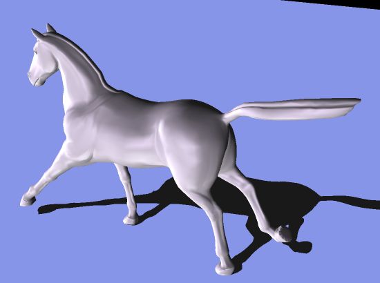
de Aguiar et al. / Automatic Conversion of Mesh Animations into Skeleton-based Animations

the model, which enables reasonably fast decomposition of
even large meshes.

   Similar to [KOF05, dATS06] in the context of optical mo-
tion capture and [TRdAS07] for volumetric segmentation,
the motion trajectories of the seed vertices throughout the
whole sequence form the input to a spectral clustering ap-
proach [NJW02] which automatically groups the l seeds into
k approximately rigidly moving groups. We capitalize on
the invariant that mutual distances between points on the              Figure 3: Approximately rigid surface patches shown in dif-
same rigid part should only exhibit a small variance while             ferent colors.
the mesh is moving.
                                                                       5. Automatic Skeleton Extraction
   In order to use spectral clustering we first construct a            Given the list of body segments, their associated seed ver-
spatial affinity matrix A. We developed an affinity criterion          tices and triangle patches, we extract the kinematic skele-
specifically for our setting that defines the entries of A as          ton structure of the animated mesh by first finding its kine-
follows:                                                               matic topology (i.e. find which body parts are adjacent) and,
                                         √ρ                            thereafter, by estimating the positions of the interconnecting
                                   σi, j +
                      Ai, j = e
                               −         S2
                                              i, j
                                                     ,        (1)      joints for the whole sequence.
                                                                          To determine which body segments are adjacent, we an-
where ρi, j = N12 ∑t δ(vi , v j ,t) is the mutual Euclidean            alyze the triangles at the boundaries of the triangle patches.
distance δi, j,t between seed vertex vi and seed vertex                Body parts A and B are adjacent if they have mutually adja-
v j over time and σi, j is its standard deviation. S =                 cent triangles in their respective patch boundaries. Unfortu-
 1                √                                                    nately, in practice a patch may be adjacent to more than one
N 2 ∑i, j
          (σi, j + ρi, j ) is a scaling term controlling the con-
vergence behavior. We construct the entries of A such that             other patch. If more than two patches are directly connected
the affinity values of vertex pairs with large average mutual          (e.g. head, torso and arm), we need to decide which seg-
distance is reduced, which forces our spectral clustering al-          ments are truly kinematically connected and which are not.
gorithm to put spatially far apart groups of vertices with sim-        Here we take a heuristic approach and consider only those
ilar motion into separate clusters.                                    patches to be adjacent that share the longest common bound-
                                                                       ary (in terms of the number of adjacent boundary triangles).
   Spectral clustering is our method of choice as it can ro-           For instance, if head, arm and torso are connected we calcu-
bustly infer complex cluster topologies as they are typical            late the number of neighboring triangles for all combinations
for our motion segmentation problem. Instead of grouping               of patch pairings (e.g. head-torso, head-arm and torso-arm)
the vertices directly based on the individual values Ai, j , spec-     and do not assign the pair head-arm as an adjacent segment
tral clustering uses the top eigenvectors of matrices derived          since it has less neighbors in comparison with the other two
from A to cluster the vertices (for details see [NJW02]). This         options. For any adjacent pair of patches, a joint has to be
makes the clustering more robust against outliers and leads            found later. Note that in our system we assume that the body
to a more robust and kinematically more meaningful seg-                part in the center of gravity of the mesh at the reference time
mentation. As an additional benefit, the optimal number of             step is the root of the hierarchy.
clusters k can be automatically calculated based on the data              In order to estimate the joint positions between two adja-
set’s eigen-gap. In our system, we automatically cluster the           cent body segments A and B quickly, we only consider the
seeds into k groups such that around 99.0% of the total vari-          information from the sets of seed vertices VA and VB located
ation of the data is explained.                                        on these segments, and not the information from all vertices
                                                                       of V . Instead of solving for the complete sequence of joint
   Using the k optimal vertex clusters, we create triangle
                                                                       positions, we significantly reduce the problem’s complexity
clusters T0 . . . Tk−1 = T by assigning each triangle ∆ =
                                                                       by first aligning the segment poses to a reference time step
(w0 , w1 , w2 ) ∈ T to the closest seed vertex class consider-
                                                                       tr (usually tr = 0), then solving for a single optimal joint po-
ing the average Euclidean distance from a seed vertex vu
                                                                       sition at ctr in the reference pose, and finally retransforming
to w0 , w1 , and w2 . The resulting clusters divide the mesh
                                                                       ctr into the original poses of A and B. To serve this purpose,
into k approximately rigid surface patches, Fig 3. Note that
                                                                       for each time step t we first compute two rigid body trans-
although a structurally motivated distance measure like the
                                                                       forms TAt→tr and TBt→tr that align the positions of the seed
geodesic distance could also be used for clustering the trian-
                                                                       vertices in both sets with the positions of the seed vertices
gles and to determine affinities in Eq. (1), our experiments
                                                                       VA at the reference time step [Hor87].
show that similar results can be achieved using simple Eu-
clidean distance which reduces the algorithm’s computation               For finding ctr we follow an idea proposed in [KOF05]
time considerably.                                                     and assume that a good estimate for the correct sequence of

                                                                                                                                      c 2008 The Author(s)
                                                                       Journal compilation c 2008 The Eurographics Association and Blackwell Publishing Ltd.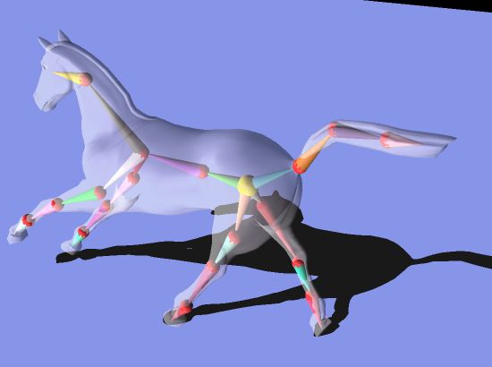
de Aguiar et al. / Automatic Conversion of Mesh Animations into Skeleton-based Animations

joint positions is the sequence of locations that minimizes
the variance in joint-to-vertex distance for all seed vertices
of the adjacent parts at all frames. Using this assumption,
[dATS06] solves for the joint location at the reference time
ctr by using a distance penalty based on the average Eu-
clidean distance to regularize the solution. Alternatively, we
use the regularization term proposed by [AKP∗ 04], which
makes the estimated joint position come closer to the cen-
troid position bt of the boundary curve between the two ad-
jacent body parts at all time steps t. Therefore, we solve for
ctr by minimizing:
          1                    1
          2 va∑
J(ctr ) =   ∗       σa (ctr ) + ∗ ∑ σb (ctr ) + α ∗ d(ctr , btr )
                ∈VA            2   vb ∈VB
                                                              (2)
where σa (ctr ) and σb (ctr ) corresponds to the Euclidean dis-
tance variance over time between the joint position ctr and
                                                                                        Figure 4: (upper) Visual comparison between the recon-
the vertex va and between ctr and vb , respectively. d(ctr , btr )
                                                                                        structed joint positions and the true positions (shown as
is the Euclidean distance between ctr and btr at the reference
                                                                                        white spheres) at four different frames. (lower) Plot of the
time step. The coefficient α is used to regularize the solution,
                                                                                        low difference in z-coordinate between the reconstructed left
making the joint position be located as closed as possible to
                                                                                        elbow joint position and the ground truth position over time
the interior of the mesh. The results in Sect. 8 were generated
                                                                                        (biped walking sequence).
using a value of α = 0.05 (which we found to be satisfactory
in our experiments).
                                                                                           After solving this equation for each pair of subsequent
   After solving Eq. 2 and finding the optimal joint location                           joints in the hierarchy we obtain a consistent kinematic
ctr , the joint positions at all other frames can be easily com-                        structure of the mesh M. To infer joint motion parameters,
puted by ct = TA−1  t→tr
                         ∗ ctr . By applying the above procedure                        i.e. a rotational transformation Tti for all joints i at all times
to all adjacent body parts we reconstruct all joint positions                           t, we first specify the skeletal pose at the first time step as ref-
for the whole sequence (see Fig. 4).                                                    erence pose (this is the best we can do given no explicit ref-
                                                                                        erence). Thereafter, we apply a Cyclic-Coordinate-Descent
6. Motion Parameters Estimation                                                         (CCD) like algorithm [Lue73,BMB87] to infer all Tti relative
                                                                                        to the reference using Euler angle parameterization. To this
A consistent parameterization of the skeletal motion in terms
                                                                                        end, we optimize one joint variable at a time by calculating
of joint parameters is only feasible in case the skeleton struc-
                                                                                        the positional error w.r.t the estimated joint positions found
ture has constant dimensions over time. However, due to
                                                                                        for that time step. Since we have all in-between joint po-
possible errors generated by aligning the body parts in the
                                                                                        sitions of each kinematic sub-chain, our method converges
reference frame (mostly caused by subtle (non-rigid) relative
                                                                                        quickly and reliably. Finally, the translation of the root is
motion between vertices on the same segment) the lengths
                                                                                        stored as additional parameter for each frame.
of the bones in the skeleton may slightly vary over time. We
enforce the bone lengths to be constant by stepping through
the hierarchy of the estimated skeleton from the root down                              7. Skinning Weight Computation
to the leaves and correcting the joint positions for each pair
of subsequent joints in the kinematic chain separately.                                 Skinning is the process of attaching the skeleton to the sur-
                                                                                        face in such a way that changes in skeletal pose lead to plau-
   Let cti be the position of a joint i and cti−1 the position of                       sible surface deformations. Although more advanced de-
its parent joint at time t. We are able to calculate the optimal                        formation schemes exist, Sect. 2.2, we decided to use the
value for the length of the bone connecting joint i − 1 and i,                          standard linear blend skinning method [LCF00] (also called
li−1,i , over time and the new positions for the joints i, ncti ,                       skeletal subspace deformation method - SSD) since it is
by minimizing the following energy:                                                     widely supported in games and animation packages.
        S(nci ,li−1,i ) =                                                       (3)        Let p0 (vi ) be the position of the vertex vi of M in the
                  N                                                                     reference pose (or rest pose), let Ttb be the transformation
                 ∑ kcti − ncti k2 + (kncti − cti−1 k − li−1,i )2 .                      of the bone b from the reference to time t, and let wb (vi )
                t=0
                                                                                        be the weight of the bone b for the vertex vi . Note that the
                                                                                                                                                  j
The first term in Eq. (3) keeps the new joint position ncti as                          bone transformation Ttb equals the transformation Tt of the
close as possible to the old position, while the second term                            preceding joint j from the hierarchy. SSD expresses the new
constrains the bone length to be the same in all frames.                                position of vertex vi at time t as pt (vi ) = ∑b (wbi Ttb p0 (vi )).

 c 2008 The Author(s)
Journal compilation c 2008 The Eurographics Association and Blackwell Publishing Ltd.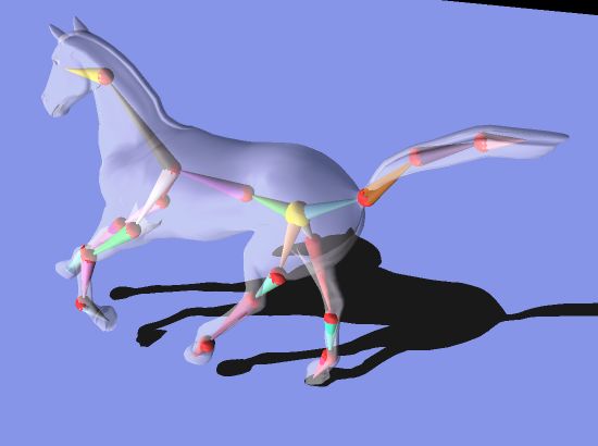
de Aguiar et al. / Automatic Conversion of Mesh Animations into Skeleton-based Animations

Therefore, in order to use the SSD method to re-animate the
sequences using a more compact representation, we need to
determine the bone weights wbi for each vertex vi , i.e. we
need to know how much each bone influences each vertex.
   Although alternative approaches for skinning weight
computation are available in the literature, we employ
the method proposed in [BP07] to determine the skinning
weight distribution for each bone. This method computes the
distribution based on the results of a heat diffusion process           Figure 5: Visual comparison between pre-defined skeleton
rather than based on simple vertex proximity to the bone,               embedded using [BP07] (l) and the skeleton extracted by our
which makes the estimation process more robust. In contrast             approach (r). Despite slight differences in the torso area, our
to their work, however, we consider the entire sequence of              estimated skeleton closely resembles the fitted template.
mesh and skeleton poses from the input when finding opti-
mal weights. In particular we first solve for the weight distri-        us ground truth data. We also have captured performances
butions wbf of each frame f separately, and thereafter average          of humans at our disposition. The dancing and capoeira se-
                                                                        quences, Fig. 6 and Fig. 8, were reconstructed by a mesh-
them to obtain the final distributions wb .
                                                                        based marker-less motion capture approach [dATSS07a].
   When computing the weight distribution wbf we regard the             The cartwheel and posing sequences (Fig. 8 and video) were
character volume as an insulated heat-conducting body and               obtained by using raw motion capture marker trajectories as
force the temperature of the bone b to be 1 and the tem-                constraints in a deformation approach [dATSS07b].
perature of all others to be 0. The weight wbf (vi ) equals the            Fig. 8 shows one original input mesh, the color-coded
equilibrium temperature at vi . For computational simplicity,           skinning weight distributions, and some poses of the
the equilibrium equation is only solved on the mesh’s sur-              original animation re-rendered using our skeleton-based
              ∂wb
face yielding ∂t f = ∆wbf + H f (pbf − wbf ) = 0. In our discrete       reparametrization. A visual comparison between our result
case this can be reformulated as                                        and the input, see Fig. 6 and several examples in the accom-
                                                                        panying video, shows that our result is visually almost indis-
                    (−∆ f + H f )wbf = H f pbf .              (4)       tinguishable from the original mesh animation and exhibits
In this equation, ∆ f is the discrete Laplacian operator at             very natural surface deformations. Furthermore, visual in-
frame f [WMKG07], pbf is a vector where pbf (vi ) equals 1 in           spection already suggests that the estimated kinematic struc-
case b is the nearest bone to vertex vi and 0 otherwise. H f is         tures are nicely embedded into the subjects at all frames and
                                                                        possess biologically plausible dimensions and hierarchies.
a diagonal matrix with entries Hii = 1/dist(vi )2 representing
                                                                        Here, we would like to note again that all these results were
the heat contribution weight of the nearest bone to vertex vi
                                                                        obtained fully-automatically. Our new representation is very
at frame f . Here, dist(vi ) is the Euclidean distance between
                                                                        compact. For the horse animation, for instance, we only need
vertex vi and the nearest bone in case it is contained in the
                                                                        to store geometry and skinning weights once, and for each
character’s volume and 0 otherwise. The final weight distri-
                                                                        time step only store 60 motion parameters (3-DOF per joint)
butions wb for each bone is the average of the weights wbf
                                                                        rather than approx. 25000 coordinate values.
for all frames.
                                                                          To get a quantitative impression of the faithfulness and
   The heat diffusion solution provides smooth and realistic
                                                                        quality of our results, we analyze individual aspects of our
blending weight distributions since it respects geodesic sur-
                                                                        method more closely.
face proximity during weight assignment rather than error-
prone Euclidean proximity [BP07]. Furthermore, our exper-               Skeleton Reconstruction Since for most synthetic data we
iments show that by computing the optimal weights from all              know the true sequence of joint positions, we are able to
available poses our skeletal animation more faithfully repro-           provide a quantitative estimate of the accuracy of our skele-
duces the entire original mesh animation.                               ton extraction and motion capture approach. Fig. 4(upper)
                                                                        shows a visual comparison between the joint positions esti-
                                                                        mated by our approach and the true joint positions, shown as
8. Experiments and Results
                                                                        white spheres, for the walking biped sequence. Fig. 4(lower)
To demonstrate and validate our algorithms, we applied it to            illustrates the accuracy of the reconstructed motion param-
a set of mesh animations generated in a variety of different            eters over time. The plot shows a comparison between the
ways, see Tab. 1 for a list. Some synthetic sequences, such as          z-coordinate of the true and estimated positions of the left
the horse sequence, Fig. 1, were generated with a mesh de-              elbow joint for the same walking sequence. The difference
formation method [SP04]. Other synthetic sequences like the             between true and estimated joint positions is very small and
bird and the walking biped (see video) were originally cre-             consistent which illustrates the robustness of our method.
ated with a skeleton-based method which conveniently gives              Similar low errors could be observed in all our sequences

                                                                                                                                       c 2008 The Author(s)
                                                                        Journal compilation c 2008 The Eurographics Association and Blackwell Publishing Ltd.
de Aguiar et al. / Automatic Conversion of Mesh Animations into Skeleton-based Animations

Figure 6: (left) Two pairs of images comparing the input (left sub-image) to our skeleton-based result (right sub-image). In
either case the renderings are visually almost indistinguishable. (right) Plot showing the low average Euclidean distance error
between input and reconstructed vertex positions for the human-sized model.

with available ground truth. The column JACC in Tab. 1
shows the average Euclidean distance error between esti-
mated joint position and true joint position for all joints over
time. Due to the lack of absolute coordinates, the error is
given in percent of the longest bounding box (B.B.) dimen-
sion of the model. In all our examples, major misalignments
between the original and the reconstructed skeleton could
only be found if the part of the input corresponding to that
joint was not prominently articulated.
   Our automatically computed bone hierarchies closely
match the skeletons that would typically be created by an-
imators. This is shown in the comparison in Fig. 5 where
we show side-by-side our result and the result of fitting
a template kinematic model with the method of Baran et
al. [BP07]. Only the topology of the root/spine area slightly
differs.                                                                                Figure 7: New poses for the input mesh can be easily gener-
                                                                                        ated by simply changing the joint parameters of the extracted
Accuracy of reparameterized animation Fig. 6(left)                                      skeleton.
shows a comparison between two frames of the input danc-
ing sequence (left sub-images) and the generated skeleton-                              show the number of frames in each sequence (FRAMES)
based animation (right sub-images). Visually, almost no dif-                            and the number of triangles in each model (NUMTRI). The
ference can be seen. The faithful reproduction of the original                          column SEGM lists the time needed for clustering and mesh
input is also shown in the accompanying video.                                          segmentation. Column SKEL lists the time needed to build
   Fig. 6(right) plots the consistently low average difference                          the skeleton and estimate all motion parameters, and col-
between the vertex positions of the input and the reparam-                              umn SKIN lists the time needed to find the blending weights.
eterized output over time for the dancing sequence. For the                             With the exception of SKIN which shows per-frame times,
human-sized figure, the error is mostly below one centime-                              all times given are for processing entire sequences. All run
ter which shows the high reconstruction quality also quanti-                            times were measured on a Laptop featuring an Intel Core
tatively. Column ACCU of Tab. 1 shows that similarly low                                Duo CPU with 1.7 GHz.
errors are observed in the other test sequences.
                                                                                        Discussion Our approach is subject to a few limitations.
Pose and animation editing Using our system, we are able                                During skeleton extraction, it is impossible to locate a joint
not only to recreate the original input based on a more com-                            if there is no relative motion between adjacent body parts.
pact representation, but can straightforwardly produce novel                            Therefore, in some of our sequences hands and feet are
postures of the input mesh, see Fig. 7. To this end, we only                            missed due to insignificant relative motion. However, we
need to modify the joint parameters which can easily be done                            consider this to be a principal problem of any data-driven
in any standard animation package. Since we have a com-                                 skeleton extraction method, and user interaction is feasible
plete set of motion parameters for the input, we can also eas-                          in this case.
ily modify aspects of the original animation by altering the
joint parameter curves of selected joints (see accompanying                                Most remaining reconstruction inaccuracies are due to
video).                                                                                 non-rigid deformation components in the input that are not
                                                                                        well explainable by a rigid skeleton and linear skinning
Computation time Tab. 1 lists the run times of each pro-                                weights. As part of future work, we plan to investigate if
cessing step in our algorithm. The second and third columns                             alternative skinning methods lead to an even further reduc-

 c 2008 The Author(s)
Journal compilation c 2008 The Eurographics Association and Blackwell Publishing Ltd.
de Aguiar et al. / Automatic Conversion of Mesh Animations into Skeleton-based Animations

            SEQUENCE        FRAMES         NUMTRI        SEGM       SKEL          SKIN                JACC                     ACCU
               Horse           47            17K           4s        17s        7s/frame               N/A                 0.56% of B.B.
               Bird            60            55K           5s        49s        10s/frame          2.9% of B.B.            0.42% of B.B.
               Biped           80            32K           5s        36s        14s/frame          1.7% of B.B.            0.52% of B.B.
             Cartwheel        120            7K            4s        63s        3s/frame               N/A                 0.81% of B.B.
              Posing          280            7K            9s        261s       4s/frame               N/A                 0.43% of B.B.
             Capoeira         150           106K          44s        244s       28s/frame              N/A                 0.47% of B.B.
              Dancing         220           106K          37s        312s       28s/frame              N/A                 0.37% of B.B.
Table 1: Given an animated mesh sequence with T triangles (NUMTRI) and N frames (FRAMES), the processing times for
segmenting the mesh into triangle patches (SEGM), to extract its kinematic structure and reconstruct its motion parameters
(SKEL), and to calculate the skinning weights based on the input data (SKIN) are shown. Also, the low average difference
between estimated joint positions and true joint locations - in percent of the maximal side length of the overall bounding box
(JACC) and the average difference between original and reconstructed vertex position (ACCU) are indicated.

tion of the residual errors, e.g. [MMG06, KCZO07, AS07,                    from 3d range data. In In Proc. of AUAI ’04 (Virginia, USA,
WPP07].                                                                    2004), pp. 18–26.

   Furthermore, skeletal reparametrization works very well              [AS07] A NGELIDIS A., S INGH K.: Kinodynamic skinning using
                                                                          volume-preserving deformations. In Symposium on Computer
for subjects whose motion is largely due to a skeleton such
                                                                          Animation (2007), pp. 129–140.
as humans and most animals. In largely non-rigidly moving
animations, such as a deforming piece of cloth, our algo-               [BMB87] BADLER N. I., M ANOOCHEHRI K. H., BARAFF D.:
                                                                          Multi-dimensional input techniques and articulated figure posi-
rithm would still determine a skeleton, but it is not physically
                                                                          tioning by multiple constraints. In SI3D (New York, NY, USA,
plausible. Therefore, mesh-based editing approaches might                 1987), pp. 151–169.
be preferred in this case [XZY∗ 07, KG06].
                                                                        [BP07] BARAN I., P OPOVI Ć J.: Automatic rigging and animation
   Despite these limitations, we have presented a simple,                 of 3d characters. ACM Trans. Graph. 26, 3 (2007), 72.
practical, robust, and easy-to-implement approach to auto-              [BS08] B OTSCH M., S ORKINE O.: On linear variational surface
matically transform an arbitrary mesh animation into a fully-             deformation methods. IEEE Transactions on Visualization and
rigged kinematic skeleton animation.                                      Computer Graphics 14, 1 (2008), 213–230.
                                                                        [dATM∗ 04] DE AGUIAR E., T HEOBALT C., M AGNOR M.,
9. Conclusion                                                              T HEISEL H., S EIDEL H.-P.: M3 : Marker-free model recon-
                                                                           struction and motion tracking from 3d voxel data. In PG 2004
We presented a fully-automatic method to extract a kine-                   (Seoul, Korea, October 2004), pp. 101–110.
matic skeleton, joint motion parameters, and surface skin-              [dATS06] DE AGUIAR E., T HEOBALT C., S EIDEL H.-P.: Auto-
ning weights from an animation of a single triangle mesh.                  matic learning of articulated skeletons from 3d marker trajecto-
The result is a compact representation of the original in-                 ries. In Proc. ISVC (2006), pp. 485–494.
put that can be easily rendered and modified in standard                [dATSS07a] DE AGUIAR E., T HEOBALT C., S TOLL C., S EIDEL
skeleton-based animation tools without having to modify                    H.-P.: Marker-less deformable mesh tracking for human shape
them in the slightest. This way, we are able to preserve the               and motion capture. In Proc. IEEE CVPR 2007 (June 2007).
great modeling flexibility of purely mesh-based approaches              [dATSS07b] DE AGUIAR E., T HEOBALT C., S TOLL C., S EIDEL
while making the resulting skeleton-less animations straight-              H.-P.: Rapid animation of laser-scanned humans. In IEEE Vir-
forwardly available to the animator’s repertoire of process-               tual Reality 2007 (Charlotte, USA, 2007), pp. 223–226.
ing tools. Our results show that the efficient combination of           [Hor87] H ORN B.: Closed-form solution of absolute orientation
skeleton learning and temporally-coherent blending weight                 using unit quaternions. Journal of the Optical Society of America
computation enables us to effectively bridge the gap between              4(4) (1987), 629–642.
the mesh-based and skeleton-based animation paradigms.                  [JT05] JAMES D., T WIGG C.: Skinning mesh animations. ACM
Acknowledgments: This work is supported by EC within                       Transactions on Graphics (Proc. SIGGRAPH) 24, 3 (2005).
FP6 under Grant 511568 with the acronym 3DTV.                           [KCZO07] K AVAN L., C OLLINS S., Z ARA J., O’S ULLIVAN C.:
                                                                          Skinning with dual quaternions. In ACM SIGGRAPH Symposium
                                                                          on Interactive 3D Graphics and Games (2007), pp. 39–46.
References
                                                                        [KG06] K IRCHER S., G ARLAND M.: Editing arbitrarily deform-
[AHLD07] AUJAY G., H ÉTROY F., L AZARUS F., D EPRAZ C.:                   ing surface animations. In SIGGRAPH ’06 (2006), ACM Press,
  Harmonic skeleton for realistic character animation. In SCA ’07         pp. 1098–1107.
  (2007), pp. 151–160.                                                  [KM04] K URIHARA T., M IYATA N.: Modeling deformable hu-
[AKP∗ 04] A NGUELOV D., KOLLER D., PANG H.-C., S RINI -                   man hands from medical images. In SCA ’04 (Aire-la-Ville,
  VASAN P., T HRUN S.: Recovering articulated object models               Switzerland, 2004), pp. 355–363.

                                                                                                                                       c 2008 The Author(s)
                                                                        Journal compilation c 2008 The Eurographics Association and Blackwell Publishing Ltd.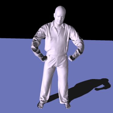
de Aguiar et al. / Automatic Conversion of Mesh Animations into Skeleton-based Animations

Figure 8: Results obtained with different input animations (left to right in each row): One frame of the input animation, color-
coded blending weight distribution, and two poses of the input recreated with our new skeleton-based representation. Our
method efficiently and fully-automatically converts mesh animations into skeleton-based animations.

[KOF05] K IRK A. G., O’B RIEN J. F., F ORSYTH D. A.: Skeletal                           [SLSK07] S HARF A., L EWINER T., S HAMIR A., KOBBELT L.:
  parameter estimation from optical motion capture data. In CVPR                          On–the–fly curve-skeleton computation for 3d shapes. In Euro-
  2005 (June 2005), pp. 782–788.                                                          graphics (Prague, Czech, September 2007), pp. 323–328.
[KT03] K ATZ S., TAL A.: Hierarchical mesh decomposition us-                            [SP04] S UMNER R. W., P OPOVIC J.: Deformation transfer for
  ing fuzzy clustering and cuts. In SIGGRAPH ’03 (New York, NY,                           triangle meshes. In SIGGRAPH ’04 (2004), ACM Press, pp. 399–
  USA, 2003), pp. 954–961.                                                                405.
[LCF00] L EWIS J. P., C ORDNER M., F ONG N.: Pose space                                 [SY07] S CHAEFER S., Y UKSEL C.: Example-based skeleton ex-
  deformation: a unified approach to shape interpolation and                              traction. In SGP ’07 (Aire-la-Ville, Switzerland, 2007), pp. 153–
  skeleton-driven deformation. In SIGGRAPH ’00 (New York, NY,                             162.
  USA, 2000), pp. 165–172.                                                              [TRdAS07] T HEOBALT C., R ÖSSL C., DE AGUIAR E., S EIDEL
[LKA06] L IEN J.-M., K EYSER J., A MATO N. M.: Simultane-                                 H.-P.: Animation collage. In Proc. SCA (2007), pp. 271–280.
  ous shape decomposition and skeletonization. In SPM ’06 (New                          [WMKG07] WARDETZKY M., M ATHUR S., K AELBERER F.,
  York, NY, USA, 2006), pp. 219–228.                                                      G RINSPUN E.: Discrete laplace operators: No free lunch. In
                                                                                          Symposium on Geometry Processing (2007), pp. 33–37.
[Lue73] L UENBERGER D. G.: Introduction to Linear and Non-
  linear Programming. New York, NY, USA, 1973.                                          [WP02] WANG X. C., P HILLIPS C.: Multi-weight enveloping:
                                                                                          least-squares approximation techniques for skin animation. In
[MG03] M OHR A., G LEICHER M.: Building efficient, accurate                               SCA ’02 (New York, NY, USA, 2002), pp. 129–138.
  character skins from examples. In SIGGRAPH ’03 (New York,
  NY, USA, 2003), pp. 562–568.                                                          [WPP07] WANG R. Y., P ULLI K., P OPOVI Ć J.: Real-time en-
                                                                                          veloping with rotational regression. ACM Trans. Graph. 26, 3
[MMG06] M ERRY B., M ARAIS P., G AIN J.: Animation space:                                 (2007), 73.
  A truly linear framework for character animation. ACM Trans.
                                                                                        [XZY∗ 07] X U W., Z HOU K., Y U Y., TAN Q., P ENG Q., G UO
  Graph. 25, 4 (2006), 1400–1423.
                                                                                          B.: Gradient domain editing of deforming mesh sequences. ACM
[NJW02] N G A. Y., J ORDAN M., W EISS Y.: On spectral cluster-                            TOG 26, 3 (2007), 84.
  ing: Analysis and an algorithm. In Proc. NIPS (2002).
                                                                                        [YBS07] YOSHIZAWA S., B ELYAEV A. G., S EIDEL H.-P.:
[Pop07] P OPPE R.: Vision-based human motion analysis: An                                 Skeleton-based variational mesh deformations. In Eurographics
   overview. Computer Vision and Image Understanding 18, 1                                (Prague, Czech, September 2007), pp. 255–264.
   (2007).                                                                              [YGZS05] YAMAUCHI H., G UMHOLD S., Z AYER R., S EIDEL
[Sha08] S HAMIR A.: A survey on mesh segmentation techniques.                             H.-P.: Mesh segmentation driven by gaussian curvature. The
   Computer Graphics Forum (2008).                                                        Visual Computer 21, 8-10 (2005), 649–658.

 c 2008 The Author(s)
Journal compilation c 2008 The Eurographics Association and Blackwell Publishing Ltd.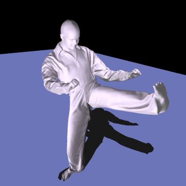
You can also read