BEDIENUNGSANLEITUNG - KBS Gastrotechnik
←
→
Page content transcription
If your browser does not render page correctly, please read the page content below
BEDIENUNGSANLEITUNG

KBS Gastrotechnik GmbH – Schoßbergstraße 26 – 65201 Wiesbaden

                                                    www.kbs-gastrotechnik.de
                                                                Stand Januar 2020
DRY BAIN MARIE WELLS
        DBM-211-S-A, DBM-311-S-A, DBM-411-S-A, DBM-511-S-A
                         OF THE SERIES

    Manual instructions                         Manuel talimatları
E                                          T
    Installation and Operation                  Kurulum ve Çalıştırma

E
    Manual de instrucciones                     Manuel d’instructions
                                           F
    Uso y mantenimiento                         Installation et fonctionnement

    Bedienungshinweise                          Manual do instruções
D                                          P
    Installation und Betrieb                    Instalação e Operação

    Instrukcja obsługi
P
    Obsługa i konserwacja

                                               DOCUMENT CODE: STRUCTURE CODE
edenox.com DRAWING OF THE DEVICE. i
edenox.com

ELECTRIC DIAGRAM / ESQUEMA DE CABLEADO / SCHEMAT
INSTALACJI ELEKTRYCZNEJ

ii
edenox.com

      LEGEND FOR ELECTRIC DIAGRAM / LEYENDA DE ESQUEMA ELÉCTRICO /
      LEGENDA SCHEMATU INSTALACJI ELEKTRYCZNEJ
      ① Thermostat,           ① Termostato,                  ① Termostat,
      ② Power switch,         ② Interruptor de alimentación, ② Wyłącznik ON/ OFF,
      ③ Connector cover A,    ③ Tapa del conector A,         ③ Złącze A,
      ④ Connector cover B,    ④ Tapa del conector B,         ④ Złącze B,
      ⑤ Heater 600W,          ⑤ Calentador 600W,             ⑤ Grzałka 600W,
      ⑥ Control light,        ⑥ Piloto de control            ⑥ Lampka kontrolna,
      ⑦ Automatic cut-off,    ⑦ Corte automático,            ⑦ Automatyczny wyłącznik,
      ⑧ Contactor.            ⑧ Contactor .                  ⑧ Stycznik.

iii
edenox.com FIGURE 1 FIGURE 2 iv
edenox.com

MANUAL INSTRUCTION INDEX

English …………………………………………….………………………………………….……….1
1. Introduction ……….……………………………………...……………………..……….………......................…........1
    1.1 Introduction to machine
    1.2 Important safety information
    1.3 Specifications Chart

2. Installation………………………………………………………………….……………………………………........…2
    2.1 General information.
    2.2 Transport, handling, unpacking, location.
    2.3 Intended use and restrictions.
    2.4 Manufacturer’s identification label description.
    2.5 Installation and assembly.
    2.6 Connections (electric, gas, water)

3. Operation…….……………………………………………………………………………………………………….…6
    3.1 General information.
    3.2 Control panel description.
    3.3 Machine settings and programs.

4. Maintenance..……………………………………………………….……………………………………………...…..7
    4.1 General safety rules.
    4.2 Machine cleaning and maintenance routine.
    4.3 Machine disposal.

5. Troubleshooting chart ……………………………………………….……..…………………………………………9
    5.1 Troubleshooting guide chart

Español ………………………………………………………………………………………..….... 11
1. Introducción ……….……………………………………...………….………..……….………......................…...... 11
2. Instalación………………………………………………………………….…………………………………….......…12
3. Uso y operación ………………………………………………………………………………………………….…14
4. Mantenimiento…………………………………………………….……………………………………………......…..17
5. Solución de problemas……………………………………………….……..…………………………………………20

Polski ………………………………………………………………………………….………….…..21
1. Wprowadzenie.…….……………………………………...………….………..……….………......................…...... 21
2. Instalacja..………………………………………………………………….…………………………………….......…22
3. Obsługa……….. ………………………………………………………………………………………………….…25
4. Konserwacja...…………………………………………………….……………………………………………......…..27
5. Rozwiązywanie problemów………………………………………….……..…………………………………………29

v
ENGLISH
1. INTRODUCTION
1.1 Description of the device and its specific models
1.2 Important safety guidelines
1.3 Technical parameters
1.1 DESCRIPTION OF THE DEVICE AND ITS SPECIFIC MODELS.
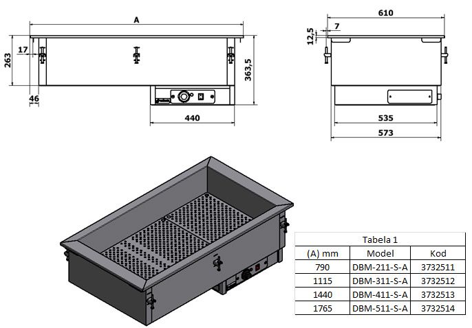
The structure of the air bain-marie is based on one air chamber (Figure 2, ‘F’). Depending on
the model, chambers may differ in size. Also, the number of the GN1/1 containers may vary: DBSA-211
has two containers 2, 311 three containers, 411 four containers, and 511 five containers. Inside the
lower part of the air chamber heating elements are located (Figure 2, ‘M’), covered from the top by
perforated plates. (Figure 2, ‘L’).
Additionally, near the outermost right-hand heating element is a holder with a temperature
sensor (Figure 2, ‘N’) of the thermal safety switch. A control panel (Figure 2, ‘D’) is located on the right-
hand side, under the air chamber (Figure 1, switch ‘C’, thermostat ‘A’, control ‘B’).
1.2 IMPORTANT SAFETY GUIDELINES.
The water bain-marie is powered by electricity. It may be operated only by personnel trained
to use professional gastronomic equipment.
Only personnel skilled in servicing of professional gastronomic equipment may maintain the
bain-marie.
While using the air bain-marie, you must strictly follow the safety instructions below:
be very careful while carrying or using a hot container of the bain-marie; make sure that no
liquid is spilled onto the heating elements, since their maximum operating temperature may
be as high as 480°C;
before cleaning the device, make sure the thermostat control is set to zero and the power
supply is disconnected from the device;
in case of a fault, disconnect the device form power supply and contact service personnel;
the device may be connected to power supply only after the fault is removed.
The following is strictly forbidden:
cleaning and repairing when the bain-marie is operating;
cooling the heating elements with water or other liquids;
1 edenox.comENGLISH
leaving the device unsupervised when it is operating;
keeping up the maximum power and temperature of the device for a long time, with the air
chamber uncovered;
using the device when it is not earthed;
operating without protective clothing;
carrying or transporting the device without a pallet or a suitable platform.
The manufacturer shall not be held liable for any damage attributable to the failure to follow
the instructions contained in this manual, hence it is recommended that you carefully read all
information herein.
Keep the manual for later use.
Warning!!!
Do not use the device if it is faulty.
1.3 TECHNICAL PARAMETERS
*CUTOUT
EXTERNAL CAPACITY VOLTAGE POWER WEIGHT
MODEL DIMENSIONS
DIMENSIONS (mm) GN 1/1 (V/Hz) (W) (kg)
(mm)
length width high length width
DBM-211-S-A 790 610 364 2 x GN1/1 770 585 230/50 1200
DBM-311-S-A 1115 610 364 3 x GN1/1 1095 585 230/50 1800
DBM-411-S-A 1440 610 364 4 x GN1/1 1420 585 230/50 2400
DBM-511-S-A 1765 610 364 5 x GN1/1 1745 585 230/50 3000 47
2. INSTALLATION
2.1 General information.
2.2 Transport, lifting, unpacking, storage.
2.3 Intended use and limitations.
2.4 Layout and description of the manufacturer’s rating label.
2.5 Installation and assembly.
2.6 Connections (electricity, gas, and water).
2.1 GENERAL INFORMATION.
The air bain-marie should be unpacked, installed and tested by qualified service personnel.
After being brought into the room where it is going to be installed, the device should be left for
approximately 6 hours so that it can achieve the ambient temperature. Then it can be connected to
power supply.
2 edenox.comENGLISH
The conductor diameter of the power cable should not be smaller than the values given in the table
below.
Designation of the power cable
Model
(type, number of conductors, cross-section area of conductors)
DBM-211-S-A, 311 PCG 3 x 1.5 mm2
DBM-411-S-A, 511 PCG 3 x 2.5 mm2
The power switch should be connected directly to the power terminal (electric cabinet), while
making it possible to safely and reliably disconnect all phases powering the device. When the circuit is
broken, the gap between the jumpers of the switch should not be smaller than 3mm.
After installation, the device must be checked for leakage conductance. The value of leakage
conductance per 1kW of the power of the device should be lower than 1mA.
Warning!!!
If an equipotential bonding bar is required, its connections must be checked.
2.2 TRANSPORT, LIFTING, UNPACKING, STORAGE.
Correct and safe transport:
• use equipment appropriate for the weight and structure of the devices;
• cover corners and sharp edges;
Before carrying:
• secure the area against unauthorised personnel;
• make sure that the load is properly secured;
• check all loose components lest they should fall when being lifted;
• try to lift the load as vertically as possible so as not to make any dents in it;
• while carrying the load, make sure that it is as near the ground as possible.
2.3 INTENDED USE AND LIMITATIONS.
Featuring the GN containers, the air bain-marie is used to keep and display hot meals that have
been prepared beforehand, allowing them to be served later.
Before using the air bain-marie, its electrical system needs to be checked for efficiency and
reliability.
After work, set the power control to 0 (Figure 1, ‘Point 0’).
Switch off the device by setting the control on the panel to 0 (Figure 1, ‘C’), and then
disconnect the power cable of the air bain-marie.
3 edenox.comENGLISH
WARNING!!!
Before the bain-marie is first put into operation, it is necessary to remove the protective film
and the protective substance from the surface of the device by wiping it with soapy water,
concentrating on the inner surface of the device’s chamber, perforated plates, and the region of the
heating elements.
2.4 LAYOUT AND DESCRIPTION OF THE MANUFACTURER’S RATING
LABEL.
The label of the device should contain the following information:
1. Manufacturer’s logo.
2. Country of origin.
3. Year of production.
4. Serial number.
5. Model.
6. Operating voltage.
7. Current frequency.
8. Rated power.
9. CE marking.
10. Disposal symbol.
4 edenox.comENGLISH
2.5 INSTALLATION AND ASSEMBLY.
The air bain-marie should installed in the following order:
remove the protective film from all metal surfaces; the bain-marie must be installed in a well
ventilated room, under a ventilation hood, if possible; it can be located on a free-standing base
or as part of a row consisting of other kitchen devices as well;
power supply should be connected to the air bain-marie in compliance with applicable
regulations;
install and connect the bain-marie in such a way that live wires cannot be accessed without
tools; the fuses of the power system of the bain-marie should be designed for 25A current;
put the air bain-marie in the place intended for installation; fix the bain-marie to the worktop,
using mounting holders (figure 2, ‘E’) on the outer vertical walls of the device; the height and
the levelling of the device should be adjusted before it is installed on the base;
connect the earth system of the device to the earth bar in such a way that it cannot be
disconnected inadvertently or unexpectedly; the power cable should contain a protective
conductor;
to connect the bain-marie, use a cable of an appropriate length, so that it can hang freely from
the device (on no account may it be tight) when firmly and permanently attached to the
terminals of the connection block and the terminals of the power plug;
The conductors diameter of the power cable should not be smaller than the values given in the
table below.
Designation of the power cable
Model
(type, number of conductors, cross-section area of conductors)
DBSA-211, 311 PCG 3 x 1.5 mm2
DBSA-411, 511 PCG 3 x 2.5 mm2
2.6 CONNECTIONS (ELECTRICITY, GAS, AND WATER).
The power cable used with the device should have 3 cords, the diameters of which may not be
smaller than suggested in the manual.
Designed to be powered by 230V, 50-60Hz mains power, the device’s power cable is equipped
with a PE protective conductor.
The electrical connection is located near the base, on the back of the device.
5 edenox.comENGLISH
WARNING!!!
Prior to first use, it is necessary to remove the protective film and the protective substance
from the surface of the bain-marie chamber and from the perforated plates by wiping them with a soft
cloth moistened with soapy water.
3. OPERATION
3.1 General information.
3.2 Description of the control panel.
3.3 Operation modes and configuration of the device.
3.1 GENERAL INFORMATION.
Follow the instructions below to make work and operation safe, as well as to ensure the
durability and fault-free operation of the device:
provide training for the personnel who is to use the device in the operation of professional
electrical gastronomic equipment;
the device may be repaired only by an authorised person;
damaged components or subassemblies should be replaced with the same items or ones with
similar durability, features and technical parameters.
The following must always be observed:
do not connect the device to the mains via a socket that is NOT provided with an earthing pin;
do not connect the device to an electrical system that has not been checked for fire safety;
do not clean or have the device maintained when connected to the power supply.
WARNING!!!
DO NOT wash the bain-marie using a water jet.
WARNING!!!
The manufacturer shall not be held liable if the device is used without the observation of this
manual or outside of its intended use.
3.2 DESCRIPTION OF THE CONTROL PANEL.
The control panel is located on the right-hand side of the bain-marie, under the air chamber
(Figure 2, ‘D’). It features (see Figure 1) a thermostat control (A), control lamp (B), and a power switch
(C). The thermostat control is used to adjust temperature in the heating chamber. It is steplessly
variable within a range of 30°C to 90°C.
Whether the desired temperature has been reached in the air chamber of the bain-marie is
shown by the control lamp (B). The power switch is used to turn on and off the device by setting it to 1
or 0 respectively.
6 edenox.comENGLISH
3.3 OPERATION MODES AND CONFIGURATION OF THE DEVICE.
A thermostat control is used to adjust the temperature of the bain-marie chamber (Figure 1,
‘A’). It is steplessly variable within a range of 30°C to 90°C. The control lamp (Figure 1, ‘B’) for the
heating elements switches on each time the temperature in the bain-marie chamber falls a few
degrees.
Air heating time in the bain-marie chamber depends largely on the tightness of the chamber
cover. Hence, the heating chamber should be covered while operating, all the more so when not all GN
container slots are used.
In order to avoid the overheating (resistance) of the heating elements, the device is provided
with a safety switch. This cuts off power form the heating elements when the temperature inside the
chamber exceeds 140°C.
4. MAINTENANCE
4.1 General safety requirements.
4.2 Cleaning and general maintenance.
4.3 Disposal of the device.
4.1 GENERAL SAFETY REQUIREMENTS.
All outer steel surfaces and all inner surfaces of the bain-marie chamber must be cleaned daily
using a small amount of detergent and lukewarm water. After being cleaned, the surfaces should be
rinsed with cold water and dried.
Do not clean acid-resistant steel surfaces with scrapers or wire cleansers, since they can
scratch the surfaces.
If the device is not going to be used for a long time, cover its surfaces, particularly the inner
surfaces of the bain-marie chamber, with a thin coat of Vaseline or a preservative that may come into
contact with food.
IMPORTANT!!!
Do not the wash the bain-marie using a water jet, since this may damage the electrical or
electronic components important for the proper operation of the device.
The device may be maintained only by trained Before using or repairing the device, read the
and specialized personnel using suitable instruction manual containing proper
protective clothing (shoes, gloves, goggles, procedures and safety information.
etc), tools, instruments, and accessories.
7 edenox.comENGLISH
4.2 CLEANING AND GENERAL MAINTENANCE.
All outer steel surfaces and all inner surfaces of the bain-marie chamber must be cleaned daily
using a small amount of detergent and lukewarm water. After cleaning, the surfaces must be rinsed
with cold water and dried, with special attention paid to the lower inner surface of the bain-marie
chamber.
Do not clean acid-resistant steel surfaces with scrapers or wire cleansers, since they can
scratch the surfaces.
If the device will not be used for a long time, cover its surfaces, particularly the inner surfaces
of the air bain-marie chamber and the perforated plates, with a thin coat of Vaseline or a preservative
that may come into contact with food.
IMPORTANT!!!
Do not the wash the bain-marie using a water jet, since this may damage the electrical or
electronic components important for the proper operation of the device.
Before starting a cleaning or maintenance When the device is being serviced, the power
procedure, disconnect the device from the cable and the plug should be in sight and on
mains. After cleaning, leave the device open to hand so that the person working can easily
dry. access them.
4.3 DISPOSAL OF THE DEVICE.
When its lifetime comes to an end, the device must be carried to an electronic and electronic
waste disposal facility.
This is indicated by a symbol on the product, in the instruction manual, and on the on the packaging.
In order to prepare the electrical bain-marie to be disposed of, it is necessary to sort the
elements of the device according to the materials they are made of.
Depending on the material these element are made of (see the symbols on the components),
they can be recycled. Having electric waste and electronic equipment recycled means an active
contribution to the protection of the environment.
Contact local authorities to obtain more information on the nearest electrical waste collection
facility.
To protect the environment, deliver waste equipment to a suitable facility in compliance with
applicable regulations.
8 edenox.comENGLISH
Make sure that the electrical equipment is Before disposing of the device, check its
delivered to a facility in which it will be technical condition.
disposed of properly. In particular, check the construction elements
Some of the materials used may be stored which may cause leakage when disposed of.
temporarily, and some must be delivered Different parts of the device are disposed
immediately to a suitable facility. differently, depending on their features (e.g.
In each case the environmental protection metals, oils, lubricants, plastic, rubber, etc.).
regulations must be observed.
5. TROUBLE-SHOOTING
5.1 Trouble-shooting information.
5.1 TROUBLE-SHOOTING INFORMATION.
IMPORTANT!!!
Electrical subassemblies may be replaced only by an authorised service technician.
It must be made a principle to disconnect the power cable from the power supply before
electrical components are replaced.
It must be made a principle to disconnect the power cable from the power supply before
electrical components are replaced.
FAULT POSSIBLE CAUSE REMEDY
- Power supply failure. Connect to power supply.
The chamber of the bain-marie - The terminals of the conductors Appropriately fix the conductors to
does not heat up; the switches and loosened on the power strip. the power strip.
the thermoregulator are on; the - The thermoregulator or the Replace the damaged components.
control lamp does not work. thermal switch is damaged.
- The switches are damaged.
- Some heating elements are Check that the heating elements
The air in the bain-marie chamber
disconnected. are properly connected.
is insufficiently heated.
- Heating elements are damaged. Replace the damaged components.
The control lamp of the heating - Control lamp burnt out. Replace the control lamp.
elements does not switch on, - The electrical circuit of the Repair the wires of the control
though these elements heat up. control lamp is open. lamp.
9 edenox.comENGLISH
The guarantee does not cover the following:
Bulbs, rubber elements, heating elements damaged by boiler scale, panes, any mechanical
damage or any damage caused by improper use of the device in violation of the instructions.
In case of a fault, remove the food kept in the device to prevent it from going bad.
EDENOX is not responsible for any commodities wasted as a result of a fault.
10 edenox.comESPAÑOL
1 INTRODUCCIÓN
1.1 Descripción del dispositivo y sus modelos específicos
1.2 Pautas importantes de seguridad
1.3 Parámetros técnicos
1.1 DESCRIPCIÓN DEL EQUIPO Y SUS MODELOS ESPECÍFICOS
La estructura del baño de aire maría se basa en una cámara de aire (Dibujo 2, 'F'). Dependiendo
del modelo, las cámaras pueden diferir en tamaño. También el número de los recipientes GN 1/1 puede
variar: DBSA-211 tiene dos recipientes 2, 311, 411 tres contenedores de cuatro contenedores, y 511 de
cinco recipientes. Dentro de la parte inferior de los elementos de calefacción de la cámara de aire se
encuentran (Dibujo 2, 'M'), cubierta de la parte superior de las placas perforadas. (Dibujo 2, 'L').
Además, cerca de la resistencia, a la derecha más exterior hay un soporte con un sensor de
temperatura (Dibujo 2, 'N') del interruptor térmico de seguridad. Un panel de control (Dibujo 2, 'D') se
encuentra en el lado derecho, debajo de la cámara de aire (Dibujo 1, el interruptor "C", el termostato 'A',
control de 'B').
1.2 PAUTAS IMPORTANTES DE SEGURIDAD
El baño de aire maría funciona con electricidad. Puede ser operado solamente por personal
entrenado para utilizar el equipo gastronómico profesional.
Sólo personal especializado en el mantenimiento de equipos gastronómicos profesionales
puede mantener el baño maría.
Durante el uso del baño de aire maría, debe seguir estrictamente las siguientes instrucciones
de seguridad:
tener mucho cuidado al llevar o usar un recipiente caliente del baño de aire maría;
asegurarse de que no se derrama líquido sobre los elementos de calefacción, ya que su
temperatura de funcionamiento máxima puede llegar hasta 480 ° C;
antes de limpiar el dispositivo, asegúrese de que el control del termostato se pone a
cero y la fuente de alimentación está desconectada de dispositivo;
en caso de un fallo, desconecte el dispositivo de la fuente de alimentación y contacte el
personal de servicio;
el dispositivo puede estar conectado a la fuente de alimentación sólo después de que se
elimina el fallo.
11 edenox.comESPAÑOL
Lo siguiente está estrictamente prohibido:
limpieza y reparación cuando el baño de aire maría está funcionando;
enfriamiento de los elementos de calefacción con agua u otros líquidos;
dejar el dispositivo sin supervisión cuando esté funcionando;
mantener la potencia máxima y la temperatura máxima del dispositivo durante mucho tiempo,
con la cámara de aire al descubierto;
utilizar el dispositivo cuando no está puesto a tierra;
operar sin la ropa de protección;
llevar o transportar el dispositivo sin una paleta o una plataforma adecuada.
El fabricante no se hace responsable de los daños derivados del incumplimiento de las
instrucciones contenidas en este manual, por lo tanto, se recomienda que lea detenidamente toda
la información en este documento.
Guarde el manual para su uso posterior.
ADVERTENCIA
No utilice el dispositivo si está defectuoso.
1.3 PARÁMETROS TÉCNICOS
* RECORTE
DIMENSIONES EXTERNAS CAPACIDAD TENSIÓN POTENCIA PESO
MODELO DIMENSIONES (W)
(mm) GN 1/1 (V/Hz) (kg)
(mm)
longitud anchura altura longitud anchura
DBM-211-S-A 790 610 364 2 x GN1/1 770 585 230/50 1200
DBM-311-S-A 1115 610 364 3 x GN1/1 1095 585 230/50 1800
DBM-411-S-A 1440 610 364 4 x GN1/1 1420 585 230/50 2400
DBM-511-S-A 1765 610 364 5 x GN1/1 1745 585 230/50 3000 47
2. INSTALACIÓN
2.1 Información general.
2.2 Transporte, elevación, desembalaje, almacenaje.
2.3 Uso previsto y limitaciones.
2.4 Estructura y descripción de la etiqueta de la calificación del fabricante.
2.5 Instalación y montaje.
2.6 Conexiones (eléctrica, de gas y agua).
12 edenox.comESPAÑOL
2.1 INFORMACIÓN GENERAL
Es necesario descomprimir el baño de aire maría, instalar y probar por personal técnico
cualificado. Después de ser llevado a la sala donde se lo va a instalar, el dispositivo se debe dejar
durante aproximadamente 6 horas para que pueda alcanzar la temperatura de ambiente.
Entonces se lo puede conectar a la fuente de alimentación.
El diámetro del conductor del cable de alimentación no debe ser menor que los valores indicados en la
siguiente tabla.
Designación del cable de alimentación
Modelo
(tipo, número de conductores, área de sección transversal de los conductores)
DBM-211-S-A, 311 PCG 3 x 1.5 mm2
DBM-411-S-A, 511 PCG 3 x 2.5 mm2
El interruptor de alimentación se debe conectar directamente al terminal de alimentación
(armario eléctrico), mientras que por lo que es posible desconectar de forma segura y fiable todas las
fases de encender el dispositivo. Cuando se rompe el circuito, la brecha entre los puentes del
interruptor no debe ser inferior a 3 mm.
Después de la instalación, el dispositivo debe ser revisado para la conductancia de fuga. El
valor de la conductancia de fuga por 1 kW de la potencia del dispositivo debe ser inferior a 1 mA.
Advertencia
Si se necesita una barra de compensación de potencial, sus conexiones deben revisarse.
2.2 TRANSPORTE, ELEVACIÓN, DESEMBALAJE, ALMACENAMIENTO
Transporte correcto y seguro:
• usar un equipo adecuado para el peso y la estructura de los dispositivos;
• cubrir esquinas y los bordes afilados;
Antes de llevar:
• asegurar el área contra personal no autorizado;
• asegurarse de que la carga esté bien sujeta;
• verificar todos los componentes sueltos para que no caigan cuando se lo levante;
• tratar de levantar la carga lo más verticalmente posible para no hacer abolladuras en ella;
• mientras llevar la carga, asegúrese de que sea lo más cerca posible del suelo.
Advertencia
El dispositivo debe ser transportado en la posición de funcionamiento. La inclinación del
dispositivo puede dañarlo.
13 edenox.comESPAÑOL
2.3 USO PREVISTO Y LIMITACIONES
Con los envases de GN, el baño de aire maría se utiliza para mantener y exhibir comidas
calientes que se han preparado de antemano, lo que les permite ser servidas después.
Antes de utilizar el baño de aire maría, su sistema eléctrico tiene que ser revisado por la
eficiencia y la fiabilidad.
Después del trabajo, establecer el control de potencia a 0 (Dibujo 1, "Punto 0").
Apague el dispositivo ajustando el control en el panel a 0 (Dibujo 1, 'C'), y luego desconecte el
cable de alimentación del baño de aire maría.
Advertencia
Antes de la primera puesta en funcionamiento del baño de aire maría, es necesario retirar la
película protectora y la sustancia protectora de la superficie del dispositivo limpiándolo con agua
jabonosa, concentrándose en la superficie interior de la cámara del dispositivo, placas perforadas, y la
región de los elementos de calentamiento.
2.4 DISPOSICIÓN Y DESCRIPCIÓN DE LA ETIQUETA DE
CALIFICACIÓN DEL FABRICANTE
14 edenox.comESPAÑOL
La etiqueta del producto deberá contener la siguiente información:
1. Logotipo del fabricante.
2. País de origen.
3. Año de producción.
4. Número de serie.
5. Modelo
6. Tensión de servicio.
7. Frecuencia actual.
8. Potencia nominal.
9. Marcado CE.
10. Símbolo de disposición
2.5 INSTALACIÓN Y MONTAJE
El baño de aire maría se lo debe instalar en el siguiente orden:
retire la película protectora de todas las superficies metálicas; el baño de aire maría debe ser
instalado en una sala bien ventilada, bajo una campana de ventilación, si es posible; que puede
estar ubicado en una base de forma independiente o como parte de una fila que consta de
otros dispositivos de la cocina también;
fuente de alimentación debe estar conectada al baño de aire maría en el cumplimiento de la
normativa aplicable;
instalar y conectar el baño de aire maría de tal manera que a los cables no se puede acceder
sin necesidad de herramientas; los fusibles del sistema eléctrico del baño de aire maría se
deben diseñar para la corriente 25A;
poner el baño de aire maría en el lugar destinado para la instalación; fijar el baño de aire maría
a la encimera, con los titulares de montaje (Dibujo 2, 'E') en las paredes verticales exteriores
del dispositivo; la altura y la nivelación del dispositivo deben ser ajustadas antes de instalarlo
en la base;
conectar el sistema de tierra del dispositivo a la barra de tierra de una manera tal que no
puede ser desconectado de forma inadvertida o inesperadamente; el cable de alimentación
debe contener un conductor de protección;
para conectar el baño de aire maría, utilice un cable de longitud adecuada, de modo que
pueda colgar libremente desde el dispositivo (en ningún caso podrá ser ajustado) cuando está
conectado con firmeza y de forma permanente a los bornes del bloque de conexión y los
terminales del enchufe de alimentación;
15 edenox.comESPAÑOL
El diámetro de los conductores del cable de alimentación no debe ser menor que los valores
indicados en la tabla a continuación.
Designación del cable de alimentación
Modelo (tipo, número de conductores, área de sección transversal de los
conductores)
DBSA-211, 311 PCG 3 x 1.5 mm2
DBSA-411, 511 PCG 3 x 2.5 mm2
2.6 CONEXIONES (ELÉCTRICA, DE GAS Y AGUA)
El cable de alimentación usado con el dispositivo debería tener 3 conducores, los diámetros de
los cuales no pueden ser menores de lo sugerido en el manual.
Diseñado para ser alimentado por 230V, tensión de red 50-60Hz, cable de alimentación del
dispositivo está equipado con un conductor de protección PE.
La conexión eléctrica se encuentra cerca de la base, en la parte posterior del dispositivo.
Advertencia
Antes de la operación, es necesario retirar la película protectora y la sustancia protectora de la
superficie de la camara del baño maría, frotándolo con un paño suave humedecido con agua jabonosa.
3. FUNCIONAMIENTO
3.1 Información general.
3.2 Descripción del panel de control.
3.3 Modos de funcionamiento y configuración del dispositivo.
3.1 INFORMACIÓN GENERAL
Siga las siguientes instrucciones para realizar el trabajo y el funcionamiento seguro, así como
para garantizar la durabilidad y el funcionamiento sin fallos del dispositivo:
proporcionar una formación para el personal que va a usar el dispositivo en la operación de
equipos profesionales gastronómicos eléctricos;
el dispositivo puede ser reparado por una persona autorizada;
componentes o subconjuntos dañados deben ser sustituidos con los mismos elementos o los
que tienen una durabilidad, características y parámetros técnicos similares.
16 edenox.comESPAÑOL
A continuación se debe mantener:
no conecte el dispositivo a la red mediante un enchufe que no se suministra con una clavija de
puesta a tierra;
no conecte el dispositivo a un sistema eléctrico que no se ha comprobado para la seguridad
contra incendios;
no limpie ni mantenga el dispositivo cuando está conectado a la fuente de alimentación.
Advertencia
NO limpie el baño de aire maría con un chorro de agua, ya que esto puede dañar los
componentes eléctricos o electrónicos, asegurando el correcto funcionamiento del dispositivo.
Advertencia
El fabricante no se hace responsable si el dispositivo se utiliza sin la observación de este
manual o fuera de su uso previsto.
3.2 DESCRIPCIÓN DEL PANEL DE CONTROL
El panel de control se encuentra en la parte derecha del baño de aire maría, en la cámara de
aire (Dibujo 2, 'D'). Cuenta con (véase el dibujo 1) un control de termostato (A), lámpara de control (B),
y un interruptor de alimentación (C). El control del termostato se utiliza para ajustar la temperatura en
la cámara de calentamiento. Es regulable de forma continua dentro de un rango de 30 ° C a 90 ° C.
Si se ha alcanzado la temperatura deseada en la cámara de aire del baño de aire maría se
muestra por la lámpara de control (B). El interruptor de encendido se utiliza para encender y apagar el
dispositivo por si se establece en 1 o 0 respectivamente.
3.3 MODOS DE FUNCIONAMIENTO Y CONFIGURACIÓN DEL
DISPOSITIVO
El termostato de control se utiliza para ajustar la temperatura de la cámara de baño de aire
maría (Dibujo 1, 'A'). Es regulable de forma continua dentro de un rango de 30 ° C a 90 ° C. La lámpara
de control (Dibujo 1, 'B') de los elementos de calefacción se enciende cada vez que la temperatura en
la cámara del baño de aire maría cae unos pocos grados.
El tiempo de calentamiento del aire en la cámara de baño de aire maría depende en gran
medida de la estanqueidad de la cubierta de la cámara. Por lo tanto, la cámara de calentamiento debe
ser cubierta durante el funcionamiento, y más aún cuando se utilizan no todas las plazas de
contenedores GN.
Con el fin de evitar el sobrecalentamiento (resistencia) de los elementos de calentamiento, el
dispositivo está provisto de un interruptor de seguridad. Esto corta la forma de alimentación de los
elementos de calefacción cuando la temperatura interior de la cámara es superior a 140 ° C.
4. MANTENIMIENTO
4.1 Requisitos generales de seguridad.
4.2 Limpieza y mantenimiento general.
4.3 Eliminación del dispositivo.
17 edenox.comESPAÑOL
4.1 REQUISITOS GENERALES DE SEGURIDAD
Todas las superficies de acero exteriores y todas las superficies internas del baño maría se deben
limpiar diariamente con una pequeña cantidad de detergente y agua tibia. Después de ser limpiadas,
las superficies deben enjuagarse con agua fría y se secan.
No limpie las superficies de acero resistentes a los ácidos con raspadores o productos de
limpieza de alambre, ya que se pueden rayar las superficies.
Si el dispositivo no se vaya a utilizar durante mucho tiempo, cubrir sus superficies, en
particular las superficies de funcionamiento, con una capa delgada de vaselina o un conservante que
puede entrar en contacto con alimentos.
IMPORTANTE
NO lo limpie al baño maría con un chorro de agua, ya que esto puede dañar los componentes
eléctricos o electrónicos, asegurando el correcto funcionamiento del dispositivo.
El dispositivo puede ser mantenido sólo por Antes de utilizar o reparar el dispositivo, lea el
personal formado y especializado, utilizando manual de instrucciones que contenga los
ropa protectora adecuada (zapatos, guantes, procedimientos correctos e información de
gafas, etc), herramientas, instrumentos y seguridad.
accesorios.
4.2 LIMPIEZA Y MANTENIMIENTO GENERAL
Todas las superficies de acero exteriores y todas las superficies internas del baño de aire maría
se deben limpiar diariamente con una pequeña cantidad de detergente y agua tibia. Después de la
limpieza, las superficies deben enjuagarse con agua fría y se secan, con especial atención a la
superficie superior del baño de aire maría.
No limpie las superficies de acero resistentes a los ácidos con raspadores o productos de
limpieza de alambre, ya que se pueden rayar las superficies.
Si el dispositivo no se vaya a utilizar durante mucho tiempo, cubrir sus superficies, en
particular las superficies de funcionamiento, con una capa delgada de vaselina o un conservante que
puede entrar en contacto con alimentos.
18 edenox.comESPAÑOL
IMPORTANTE
NO lo limpie al baño maría con un chorro de agua, ya que esto puede dañar los componentes
eléctricos o electrónicos, asegurando el correcto funcionamiento del dispositivo.
Antes de iniciar un procedimiento de limpieza Cuando se repara el aparato, el cable eléctrico
o mantenimiento, desconecte el aparato de la y el enchufe deben estar a la vista y a la mano
red. Después de la limpieza, deje el dispositivo para que la persona que trabaja puede acceder
abierto para que se seque. a ellos fácilmente.
4.3 ELIMINACIÓN DEL DISPOSITIVO
Cuando la vida útil llega a su fin, el dispositivo se lo debe llevar a una instalación de eliminación
de residuos electrónicos y eléctricos.
Esto se indica mediante un símbolo en el producto, en el manual de instrucciones y en el
envase.
Con el fin de preparar el baño de aire maría para ser eliminado, es necesario ordenar los
elementos del dispositivo de acuerdo con los materiales de que están hechos.
Dependiendo del material de que estos elementos están hechos (ver los símbolos en los
componentes), pueden ser reciclados. Tener residuos eléctricos y equipos electrónicos reciclados
significa una contribución activa a la protección del medio ambiente.
Póngase en contacto con las autoridades locales para obtener más información sobre la
instalación de recogida de residuos eléctricos más cercana.
Para proteger el medio ambiente, la entrega de conjunto de residuos a una instalación
adecuada de conformidad con la normativa aplicable.
Asegúrese de que el equipo eléctrico se Antes de desechar el dispositivo, verificar su
entrega a un centro en el que se dispondrá de estado técnico.
manera adecuada. En particular, compruebe los elementos de
Algunos de los materiales utilizados pueden construcción que pueden causar fugas cuando
ser almacenados temporalmente, y algunos son desechados.
deben ser entregados inmediatamente a una Diferentes partes del dispositivo se disponen
instalación adecuada. de manera diferente, en función de sus
En cada caso se deben observar las normas de características (por ejemplo, metales, aceites,
protección del medio ambiente. lubricantes, plásticos, caucho, etc.)
19 edenox.comESPAÑOL
5. SOLUCIÓN DE PROBLEMAS
5.1 INFORMACIÓN DE FALLOS Y AVERĺAS
IMPORTANTE
Subconjuntos eléctricos podrán ser sustituidos por un técnico de servicio autorizado.
Debe seguir el principio de desconectar el cable de alimentación de la fuente de alimentación
antes de sustituir los componentes eléctricos.
Debe seguir el principio de desconectar el cable de alimentación de la fuente de alimentación
antes de sustituir los componentes eléctricos.
FALLO CAUSA POSIBLE SOLUCIÓN
- Fallo de la fuente de Conectar a la fuente de
alimentación. alimentación.
La cámara del baño de aire maría
- Los terminales de los conductores Fijar adecuadamente los
no se calienta; los interruptores y
se aflojaron en la regleta. conductores a la regleta.
el termorregulador están puestos;
- El termorregulador o el Reemplazar los componentes
la lámpara de control no funciona.
interruptor térmico está dañado. dañados.
- Los interruptores están dañados.
- Algunos elementos calefactores Compruebe que los elementos de
están desconectados. calentamiento están conectados
La cámara de baño de aire maría
- Los elementos de calefacción correctamente.
no se calienta lo suficiente.
están dañados. Reemplace los componentes
dañados.
La lámpara de control de los - La lámpara de control se ha Vuelva a colocar la lámpara de
elementos de calefacción no se quemado. control.
enciende, aunque estos elementos - El circuito eléctrico de la lámpara Repare los cables de la lámpara de
se calientan. de control está abierto. control.
La garantía no cubre lo siguiente:
Bulbos, elementos de goma, elementos de calefacción dañados por la escala de calderas,
paneles, cualquier daño mecánico o de cualquier daño causado por el uso incorrecto del dispositivo en
violación de las instrucciones.
En caso de un fallo, retire la comida mantenida en el dispositivo para evitar que se
eche a perder. EDENOX no se responsabiliza de cualquier mercancía desperdiciada, como
resultado de un fallo.
20 edenox.comPOLSKI
1. WPROWADZENIE
1.1 Prezentacja urządzenia i poszczególnych modeli
1.2 Ważne aspekty bezpieczeństwa
1.3 Parametry techniczne
1.1 PREZENTACJA URZADZENIA I POSZCZEGÓLNYCH MODELI
Budowa bemaru powietrznego jednokomorowego oparta jest na jednej komorze powietrznej
(Rysunek 2 „F”). Wielkość komory zależna jest od modelu urządzenia. Modele mogą pomieścić
określona liczbę pojemników GN 1/1: DBSA-211 – 2 pojemniki, 311 – 3 pojemniki, 411 – 4 pojemniki
oraz 511 – 5 pojemników. Wewnątrz komory powietrznej, w jej spodniej części rozmieszczone są
elementy grzejne (Rysunek 2 „M”), przykryte od góry perforowanymi półkami (Rysunek 2 „L”).
Dodatkowo w pobliżu skrajnego prawego elementu grzejnego umieszczony jest uchwyt z
czujnikiem temperatury (Rysunek 2 „N”) termicznego wyłącznika bezpieczeństwa. Poniżej komory
powietrznej, po prawej stronie znajduje się panel sterowania urządzenia (Rysunek 2 „D”) (Rysunek 1 –
włącznik „C”, termostat „A”, kontrolka „B”).
1.2 WAŻNE ASPEKTY BEZPIECZEŃSTWA.
Bemar powietrzny zasilany jest prądem elektrycznym. Może być
obsługiwany przez personel, który został przeszkolony w zakresie obsługi
profesjonalnych urządzeń gastronomicznych.
Serwis bemaru może być przeprowadzony przez personel
posiadający odpowiednie przeszkolenie w zakresie serwisowania
profesjonalnych urządzeń gastronomicznych.
Podczas pracy z bemarem powietrznym należy ściśle przestrzegać następujących zasad
bezpieczeństwa:
zachowaj szczególna ostrożność przenosząc lub operując gorącym wsadem bemaru, nie
rozlewaj płynów na elementy grzejne – maksymalna temperatura ich pracy sięga 480°C;
zanim rozpoczniesz myć urządzenie upewnij się, że pokrętło termostatu jest w pozycji zerowej,
a całe urządzenie odłączone jest od zasilania;
po zaistnieniu usterki odłącz urządzenie od zasilania i wezwij do niego serwis;
podłącz urządzenie do zasilania dopiero po usunięciu awarii.
Stanowczo zabrania się:
czyszczenia oraz usuwania usterek, podczas gdy bemar jest włączony;
schładzania elementów grzejnych wodą lub innymi cieczami;
pozostawiać działające urządzenie bez nadzoru;
podtrzymywania długotrwałej pracy urządzenia na pełnej mocy i w najwyższej temperaturze z
odkrytą komorą powietrzną;
pracy z urządzeniem bez podłączonego uziemienia;
pracy bez odzieży ochronnej z urządzeniem;
przenoszenia lub transportu urządzenia bez palety, lub przystosowanego do tego podestu.
Producent nie ponosi odpowiedzialności za szkody wynikające z nieprzestrzegania zasad
umieszczonych w instrukcji, dlatego zalecamy uważnie przeczytać informacje zawarte w niniejszej
instrukcji użytkowania
Prosimy zachować instrukcję w celu wykorzystania jej w przyszłości.
Uwaga !!! Nie uruchamiać wyrobu niesprawnego technicznie.
21 www.edenox.plPOLSKI
1.3 PARAMETRY TECHNICZNE
MODEL WYMIARY ZEWNĘTRZNE (mm) POJEMNOŚĆ GN *OTWÓR MODEL WYMIARY
1/1 MONTAŻOWY ZEWNĘTRZNE (mm)
Dł. Szer. Wys. Dł. Szer.
DBM-211-S-A 790 610 364 2 x GN1/1 770 585 230/50 1200
DBM-311-S-A 1115 610 364 3 x GN1/1 1095 585 230/50 1800
DBM-411-S-A 1440 610 364 4 x GN1/1 1420 585 230/50 2400
DBM-511-S-A 1765 610 364 5 x GN1/1 1745 585 230/50 3000
INSTALACJA
2.1 Informacje ogólne.
2.2 Transport, podnoszenie, rozpakowanie, przechowywanie.
2.3 Przeznaczenie i ograniczenia.
2.4 Wygląd i opis naklejki znamionowej producenta.
2.5 Instalacja i montaż.
2.6 Podłączenie urządzenia (elektryczne, gazowe, wodne).
2.1 INFORMACJE OGÓLNE.
Bemar powietrzny powinien być rozpakowany, zainstalowany i przetestowany przez
wykwalifikowanych pracowników serwisu. Po wniesieniu urządzenia do docelowego pomieszczenia
należy pozostawić go na około 6 godzin, do momentu aż osiągnie temperaturę otoczenia. Po tym
czasie można przystąpić do podłączania urządzenia do zasilania.
Kabel zasilający powinien mieć przekrój żyły nie mniejszy niż wartości podane w tabeli poniżej.
Oznaczenie przewodu zasilającego
Model
(gatunek, liczba żył i przekrój poprzeczny żyły)
DBM-211-S-A, 311 PCG 3 x 1,5 mm2
DBM-411-S-A, 511 PCG 3 x 2,5 mm2
Wyłącznik prądu powinien zapewniać trwałe i bezpieczne rozłączenie wszystkich faz prądu
zasilających urządzenie; powinien być połączony bezpośrednio z terminalem zasilającym (skrzynką
elektryczną); po rozłączeniu obwodu odstęp między zworkami wyłącznika nie powinien być mniejszy
niż 3mm.
Po instalacji urządzenia należy sprawdzić upływność prądu. Wartość upływności przypadająca
na 1kW mocy urządzenia powinna być mniejsza niż 1mA.
Uwaga !!!
Należy sprawdzić podłączenie do listwy ekwipotencjalnej, jeśli taka jest wymagana.
22 www.edenox.plPOLSKI
2.2 TRANSPORT, PODNOSZENIE, ROZPAKOWANIE,
PRZECHOWYWANIE.
Prawidłowy i bezpieczny transport i przenoszenie:
• używaj sprzętu najlepiej dopasowanego do ciężaru i budowy urządzeń;
• osłoń ostre krawędzie i naroża;
Przed przenoszeniem:
• zabezpiecz plac manewrowy przed niepowołanym wtargnieciem na niego innych osób;
• sprawdź czy na pewno ładunek jest poprawnie zabezpieczony;
• upewnij się, że podczas podnoszenia nie spadną żadne nieumocowane komponenety;
• staraj się manewrować w pionie w celu unikniecia obtłuczeń;
• podczas przenoszenia urządzenia staraj się operować na możliwie najniższym poziomie.
2.3 PRZEZNACZENIE I OGRANICZENIA.
Bemar powietrzny służy do eksponowania i przechowywania wcześniej przygotowanych
gorących potraw w pojemnikach GN przed podaniem do konsumpcji.
Przed rozpoczęciem pracy z bemarem powietrznym, należy sprawdzić sprawność i
niezawodność instalacji elektrycznej.
Po zakończeniu pracy ustaw pokrętło mocy w pozycji „0” (Rysunek 1 „Punkt 0”).
Wyłącz urządzenie wyłącznikiem (wyłącznik w pozycji „0”) znajdującym się na panelu
sterowania (Rysunek 1 „C”) a następnie odłącz kabel zasilający bemar powietrzny.
UWAGA !!!
Przed pierwszym użyciem należy usunąć folie ochronną oraz substancję ochronną z
powierzchni bemaru, skupiając się na wewnętrznej powierzchni komory urządzenia, perforowanych
półkach oraz okolicach elementów grzejnych przecierając je miękką szmatką nasączoną wodnym
roztworem mydła.
23 www.edenox.plPOLSKI
2.4 WYGLĄD I OPIS NAKLEJKI ZNAMIONOWEJ PRODUCENTA.
Naklejka umieszczona na urządzeniu powinna zawierać następujące informacje:
1. Logo producenta.
2. Kraj pochodzenia produktu.
3. Rok produkcji.
4. Numer seryjny.
5. Model.
6. Napięcie pracy.
7. Częstotliwość prądu.
8. Moc znamionowa.
9. Symbol CE.
10. Symbol złomowania.
2.5 INSTALACJA I MONTAŻ.
Instalację bemaru powietrznego należy przeprowadzić w określonym poniżej porządku:
usuń folie ochronną ze wszystkich metalowych powierzchni; bemar powinien być umieszczony
w dobrze wentylowanym pomieszczeniu, jeśli istnieje taka możliwość – pod okapem
wentylacyjnym; bemar może być zainstalowany w podstawie wolnostojącej lub w ciągu, z
innymi urządzeniami kuchennymi;
24 www.edenox.plPOLSKI
przyłącze elektryczne bemaru powietrznego powinno być wykonane zgodnie z obowiązującymi
przepisami;
instalacja i podłączenie powinno być wykonane w taki sposób by uniemożliwiało dostęp do
elementów mogących znajdować się pod napięciem bez konieczności użycia narzędzi;
bezpieczniki w instalacji zasilającej bemar powinny być przeznaczone do prądu 25A;
umieść bemar powietrzny w odpowiednio do tego przygotowanym miejscu; przymocuj bemar
do blatu korzystając z uchwytów do mocowania (Rysunek 2 „E”) dostępnych na zewnętrznych,
pionowych ściankach urządzenia; regulacja wysokości oraz wypoziomowanie urządzenia
powinno być wykonane przed zamocowaniem urządzenia w podstawie;
podłącz uziemienie urządzenia do listwy uziemiającej tak by nie można było odłączyć go w
sposób nieświadomy i nieoczekiwany; przewód zasilający powinien zawierać przewód
ochronny;
do podłączenia urządzenia użyć przewodu o odpowiedniej długości; użyty przewód powinien
zwisać swobodnie z urządzenia (w żadnym przypadku przewód nie może być napięty),
powinien być dokładnie i trwale przymocowany do zacisków kostki przyłączeniowej i oraz do
zacisków wtyczki zasilającej;
Kabel zasilający powinien mieć przekrój żył nie mniejszy niż wartości podane w tabeli poniżej.
Oznaczenie przewodu zasilającego
Model
(gatunek, liczba żył i przekrój poprzeczny żyły)
DBM-211-S-A, 311 PCG 3 x 1,5 mm2
DBM-411-S-A, 511 PCG 3 x 2,5 mm2
2.6 PODŁĄCZENIE URZĄDZENIA (ELEKTRYCZNE, GAZOWE, WODNE).
Kabel zasilający zastosowany w urządzeniu powinien mieć 3 żyły, których przekroje nie mogą
być mniejsze niż sugerowane w niniejszej instrukcji.
Urządzenie przystosowane jest do zasilania z sieci 230V, 50-60Hz. Przewód zasilający
wyposarzony jest w kabel ochronny PE.
Przyłącze elektryczne znajduje przy podstawie, w tylnej części urządzenia.
UWAGA !!!
Przed pierwszym użyciem należy usunąć folię i substancję ochronną z powierzchni komory
bemaru oraz perforowanych półek przecierając je miękką szmatką nasączoną wodnym roztworem
mydła.
3. OBSŁUGA
3.1 Informacje ogólne.
3.2 Opis panelu sterowania.
3.3 Tryby pracy I konfiguracja urządzenia.
25 www.edenox.plPOLSKI
3.1 INFORMACJE OGÓLNE.
Chcąc zapewnić bezpieczeństwo pracy, obsługi, długotrwałego i bezawaryjnego
funkcjonowania urządzenia należy przestrzegać następujących zasad:
przeszkolić personel obsługujący urządzenie w zakresie esploatacji profesjonalnych
elektrycznych urzadzeń gastronomicznych;
wszelkich napraw urzadzenia może dokonywać osoba do tego uprawniona;
uszkodzone komponenty lub podzespoły powinny być wymienione na identyczne lub takie,
które posiadają tą samą żywotność, właściwości i parametry techniczne.
Zabrania się:
podłaczać urządzenie do sieci za pośrednictwem gnazdka NIE posiadającego kołka
uziemiającego;
podłączania urządzenia do intalacji elektrycznej nie sprawdzonej pod kątem ochrony
przeciwporażeniowej;
mycia, czyszczenia oraz dokonywania napraw serwisowych urzadzenia podłączonego do sieci
elektrycznej.
UWAGA !!! NIE UŻYWAJ strumienia wody do mycia elektrycznego bemaru powietrznego.
UWAGA !!! Za użytkowanie urządzenia niezgodne z przeznaczeniem lub zaleceniami niniejszej
instrukcji, producent nie ponosi żadnej odpowiedzialności.
3.2 OPIS PANELU STEROWANIA.
Panel sterowania usytuowany jest po prawej stronie urządzenia pod komorą powietrzną
bemaru (Rysunek 2 „D”). Znajduje sie na nim (patrz Rysunek 1) pokrętło termostatu „A”, lampka
kontrolna „B” oraz włącznik prądowy „C”. Pokrętło termostatu służy do regulacji temperatury
powietrza w komorze grzewczej. Zakres kontroli temperatury jest płynny od 30°C do 90°C.
Lampka kontrolna „B” sygnalizuje osiągnięcie żądanej temperatury w komorze powietrznej
bemaru. Włącznikiem prądowym uruchamiamy urządzenie (włącznik w pozycji „1”) lub odłączamy od
zasilania (włącznik w pozycji „0”).
3.3 TRYBY PRACY I KONFIGURACJA URZĄDZENIA.
Regulacja temperatury komory bemaru odbywa się za pomocą pokrętła termostatu (Rysunek 1
„A”). Regulacja jest płynna w zakresie 30°C – 90°C. Lampka kontrolna (Rysunek 1 „B”) sygnalizują
nagrzewanie się elementów grzejnych zapala się każdorazowo gdy temperatura wewnątrz komory
bemaru spadnie o kilka – kilkanaście stopni.
Czas nagrzewania powietrza w komorze bemaru do oczekiwanej temperatury zależy w głównej
mierze od szczelności pokrywy komory. Dlatego ważne jest by w trakcie pracy urządzenia komora
grzewcza była przykryta zwłaszcza gdy nie wszystkie miejsca na pojemniki GN są wykorzystywane.
W celu uniknięcia przegrzania elementów grzejnych (rezystancji) w urządzeniu zastosowano
termiczny wyłącznik bezpieczeństwa. Wyłącznik ten odcina zasilanie elemetów grzejnych w momencie
gdy temperatura wewnątrz komory przekroczy 140°C.
26 www.edenox.plYou can also read