Biphasic epoxy-ionic liquid structural electrolytes: minimising feature size through cure cycle and multifunctional block-copolymer addition ...
←
→
Page content transcription
If your browser does not render page correctly, please read the page content below

Multifunctional Materials

PAPER • OPEN ACCESS

Biphasic epoxy-ionic liquid structural electrolytes: minimising feature size
through cure cycle and multifunctional block-copolymer addition
To cite this article: Quan Wendong et al 2021 Multifunct. Mater. 4 035003

View the article online for updates and enhancements.

                               This content was downloaded from IP address 46.4.80.155 on 19/09/2021 at 15:58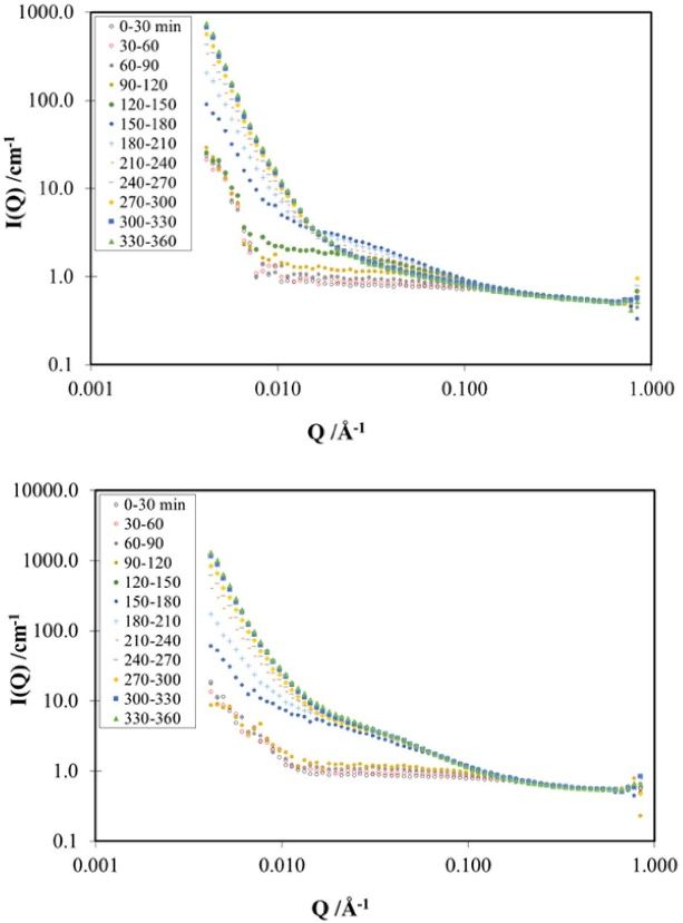
Multifunct. Mater. 4 (2021) 035003 https://doi.org/10.1088/2399-7532/ac1ea7
Multifunctional Materials
PAPER
Biphasic epoxy-ionic liquid structural electrolytes: minimising
OPEN ACCESS
feature size through cure cycle and multifunctional
RECEIVED
13 April 2021 block-copolymer addition
REVISED
6 August 2021 Quan Wendong1, John Dent1, Valeria Arrighi2, Leide Cavalcanti3, Milo S P Shaffer4
ACCEPTED FOR PUBLICATION
18 August 2021
and Natasha Shirshova1,∗
1
Department of Engineering, Durham University, South Road, Durham DH1 3LE, United Kingdom
PUBLISHED 2
9 September 2021 School of Engineering and Physical Sciences, Institute of Chemical Sciences, Heriot-Watt University, Edinburgh EH14 4AS,
United Kingdom
3
Science Technology Facilities Council, Isis Neutron and Muon Source, Harwell Campus, Oxfordshire OX11 0QX, United Kingdom
Original content from 4
this work may be used
Department of Materials, Imperial College London, South Kensington Campus, London SW7 2AZ, United Kingdom
∗
under the terms of the Author to whom any correspondence should be addressed.
Creative Commons
Attribution 4.0 licence.
E-mail: natasha.shirshova@durham.ac.uk
Any further distribution Keywords: structural electrolyte, bicontinuous structure, reaction induced phase separation, block-copolymer,
of this work must epoxy resin, ionic liquid
maintain attribution to
the author(s) and the title Supplementary material for this article is available online
of the work, journal
citation and DOI.
Abstract
Structural electrolytes provide mechanical properties approaching structural resin combined with
a high degree of ionic conductivity. Here, structural electrolytes based on bisphenol A diglycidyl
ether and the ionic liquid 1-ethyl-3-methylimidazolium bis(trifluoromethylsulfonyl) imide
(EMIM-TFSI) were synthesised through reaction induced phase separation (RIPS) using
isophorone diamine (iPDA) as a curing agent. The microstructure and properties of the resulting
materials were controlled through both the initial formulations and the curing temperature.
Curing at room temperature generated a bi-continuous structure and improved both mechanical
performance and ionic conductivity of the resulting structural electrolytes. The balance between
properties can be systematically adjusted; for example, a promising Young’s modulus of 800 MPa
was obtained simultaneously with an ionic conductivity of 0.28 mS cm−1 , for a formulation
containing 35 vol% EMIM-TFSI. The lengthscale of the structural features was reduced by an order
of magnitude by introducing multifunctional block-copolymers (MF-bcP) based on glycidyl
methacrylate (GMA) and quaternised (2-dimethylamino)ethyl methacrylate (DMAEMA). Small
angle neutron scattering (SANS), obtained during curing, identified at least two structural phases
of different length scale, for the formulations containing MF-bcP, in agreement with
microstructures observed using scanning electron microscopy. Such structural electrolytes may be
required when using structural electrodes that also have finer characteristic lengthscales. The
addition of the MF-bcP to formulations containing 35 vol% EMIM-TFSI produced structural
electrolytes with a Young’s modulus of 530 MPa and an ionic conductivity of 0.64 mS cm−1 .
1. Introduction
Structural composite materials are increasingly used in electric vehicles, driven by the need to increase range.
This rapid uptake has motivated research into composite ‘structural power’ storage devices. These
multifunctional materials are capable of storing electrical energy, as batteries, capacitors and supercapacitors,
while simultaneously carrying significant mechanical load [1–6]. Whilst a number of components require
development or optimisation to achieve true multifunctionality, the electrolyte has been highlighted as one
of the main challenges [6]. Electrolytes for structural energy storage devices, i.e. structural electrolytes, must
have high ionic conductivity and good mechanical performance. These two properties are known [7, 8] to
© 2021 The Author(s). Published by IOP Publishing LtdMultifunct. Mater. 4 (2021) 035003 Q Wendong et al
Figure 1. Summary of existing literature data on electrolytes with improved mechanical performance; (⃝)—PEO based;
(□)—epoxy based RIPS; (△)—vinyl monomers based RIPS and other systems, such as polymer + filler; (∗)—refilled, two-step
process. Numbers next to symbols represent reference number.
have inverse relationship due to the opposite requirements, i.e. high ionic conductivity implies flexibility of
the polymer chains and good mechanical properties require rigidity of these polymer chains. The inverse
relationship between these two properties can be observed in the figure 1, which presents an overview of
some of the best combination of the mechanical properties and ionic conductivity, presented in the literature
to date.
Multifunctional materials/devices improve overall system performance by enhancing efficiencies between
individual materials that provide separate functions; although the properties of the multifunctional material,
in general, will be inferior to those of the monofunctional equivalents, the combined mass (or volume) may
nevertheless be reduced [9]. Targets proposed in the literature [7] for structural electrolytes relevant to
multifunctional energy storage devices are 1 mS cm−1 and 1 GPa for ionic conductivity and Young’s
modulus, respectively.
To date, the most promising performance has been shown by electrolytes obtained through reaction
induced phase separation (RIPS). These systems have a bicontinuous structure in which one of the phases is
responsible for the ion conduction while the other phase provides mechanical strength and modulus.
Established systems include vinyl [2, 8, 10] and epoxy-based formulations [7, 11–13]. All these systems are
initially homogeneous, but phase separate during reaction when the growing polymer chains become
insoluble in the porogen/liquid electrolyte.
Epoxy-based systems are attractive for their mechanical properties, good adhesive properties and high
thermal and chemical stability, as well as their widespread use in fibre composite systems. In order to
introduce ionic conductivity, a range of liquid electrolytes have been explored, including ionic liquids (ILs),
lithium salts, organic solvents, as well as polymers and nano-particles, both as individual compounds and in
combination [7, 11, 12, 14–16].
Structural electrolytes can also be formed via RIPS using a two stage process, in which the reaction is
performed in the presence of a sacrificial porogen which is then removed, and refilled with the final
electrolyte [8, 17]. For example an ionic conductivity of 0.71 mS cm−1 was achieved by refilling the porous
structure formed after removal of a low molecular weight polyethylene glycol with 1 M LiPF6 in ethylene
carbonate/diethyl carbonate [17]. In that work, the structural phase, formed using an epoxy resin with
multiple oxirane rings, a block copolymer and reinforced using nano-cellulose, had a Young’s modulus of
0.65 GPa. However, the manufacturing complexity of this approach makes it less applicable to real
applications than single step RIPS methods (‘in situ structural electrolytes’).
The properties of RIPS-based structural electrolytes depend strongly on the composition of the initial
mixture and the curing conditions. For in situ structural electrolytes based on epoxy formulations, ILs and
their lithium salt solutions are the most widely studied liquid electrolytes/porogens [7, 11, 12, 14]. Materials
with a wide range of ionic conductivities and mechanical performance have been reported depending on
type and proportion of epoxy, curing agent, IL and additives [7, 8, 11, 12, 14, 18].
2Multifunct. Mater. 4 (2021) 035003 Q Wendong et al
Bisphenol A diglycidyl ether (DGEBA) is among the extensively used epoxy resins for structural
applications and has been widely studied for RIPS-based structural electrolytes, particularly in combination
with 1-ethyl-3-methylimidazolium bis(fluorosulfonyl)imide (EMIM-TFSI). Using blends of DGEBA with a
tetrafunctional epoxy resin resulted in a better combination of mechanical performance and ionic
conductivity [11] in comparison to blends containing poly(ethylene glycol) (PEG) based epoxy resins, such
as poly(ethylene glycol diglycidyl ether) (PEGDGE) [14]. Addition of PEGDGE to DGEBA resulted in an
electrolyte with a maximum tensile strength of 0.8 MPa, Young’s modulusMultifunct. Mater. 4 (2021) 035003 Q Wendong et al
Figure 2. Effect of ionic liquid content on properties of epoxy-based formulations. All samples were cured using Cycle 1
(60 ◦ C and 80 ◦ C) and post-cured at 120 ◦ C.
In this work, the IL (EMIM-TFSI) concentration was varied in the initial formulations from 10 to
60 vol% without any evidence for macroscale/gross phase separation. The homogeneity of the samples was
determined by measuring an ionic conductivity of the top and the bottom part of the samples. The
formation of homogeneous samples indicated that phase separation was slower compared to the curing
process. For formulations containing less than 30 vol% of EMIM-TFSI no measurable ionic conductivity was
detected but the introduction of even 10 vol% led to a dramatic drop (∼17%) in the mechanical modulus of
the cured formulations (figure 2). Increasing IL content from 30 vol% to 60 vol% led to a further drop in
mechanical performance but an increase in ionic conductivity (figure 2). At 60 vol%, the cured formulations
became too fragile to handle, and no further increase in IL content was attempted. The observed inverse
trend between mechanical performance and ionic conductivity of the formulations studied was in a good
agreement with the literature [7, 8, 10, 11].
As typically observed, the modulus fell as the ionic conductivity rose, with formulations within the
intermediate 30–40 vol% region presenting the best combination of properties among the formulations
studied, although still relatively low. This poor trade-off is likely due to the microstructure of the structural
electrolytes, since the ideal bicontinuous strut morphology was not one of the microstructures obtained
(figure SI1, see supporting information, SI available online at stacks.iop.org/MFM/4/035003/mmedia).
2.2. Effect of the curing conditions on the properties and morphology of the structural electrolytes
One of the parameters influencing the morphology of the epoxy based blends is the cure temperature
[22–24]. In particular, the relative rates of the cross-linking reaction and phase separation are crucial. Both
processes will be affected by temperature changes [22] but, in general, to a different extent.
The curing cycle was modified to add a room temperature curing step (Cycle 2) with the expectation that
the phase segregation would slow more rapidly than the curing reaction. The addition of a room temperature
curing step does not have a detrimental effect on the mechanical properties of the pure DGEBA cured using
isophorone diamine (iPDA) [25]. When this new cure cycle (Cycle 2) was applied to the intermediate
formulations containing 33, 35 and 40 vol% of EMIM-TFSI, it led to the formation of a bicontinuous
structure (figure 3) with dramatically improved performance (figure 4). Addition of the room temperature
step does not only alters the shape but also the scale of the microstructural features: for example, sample
IL35C1 (C1 here indicates curing Cycle 1, without a room temperature step; see section 4 for more details)
had a hierarchical microstructure which consisted of at least three different types of features, similar to one
reported previously [7]. The epoxy formed a continuous phase at a coarse scale (order of 100 µm) and in this
phase, randomly distributed droplets of IL were observed (figures SI1(b)–(d)). The coarse, continuous epoxy
phase was surrounded by connected spherical nodules (SI1(b)–(d)) with an average size of 13.9 ± 4.1 µm.
The IL35 formulations cured at room temperature (Cycle 2) not only had a bicontinuous structure but the
scale of the struts was almost order of magnitude smaller (1.4 ± 0.44 µm). Similar changes in the scale of the
features were observed for the other formulations studied.
As expected [26], increasing the porogen content (in this case, the IL) resulted in increased spacing
between struts, (figure 3). Surprisingly, the size of structural features changed more noticeably when the
EMIM-TFSI content increased from 33 to 35 vol% whilst a further increase to 40 vol% did not lead to
significant changes in the size of the features.
4Multifunct. Mater. 4 (2021) 035003 Q Wendong et al
Figure 3. SEM micrographs of structural electrolytes containing (a) 33 vol%: (b) 35 vol% and (c) 40 vol% of IL cured using Cycle
2 with addition of a room temperature step.
Figure 4. Effect of the curing cycle on the properties of epoxy based formulations with different IL contents (33, 35 and 40 vol%,
as indicated). (▲) Cycle 1; (•) Cycle 2.
Figure 5. SEM micrographs of structural electrolytes containing 35 wt% IL and various amount of MF-bcP1: (a) 0 wt%;
(b) 1 wt%; (c) 2.5 wt%, (d) 5 wt% and (e) 7.5 wt%.
5Multifunct. Mater. 4 (2021) 035003 Q Wendong et al
Table 1. Effect of concentration of MF-bcP1 on properties of the epoxy based formulations.
MF-bcP1 Young’s Ionic conductivity
Sample IL content (vol%) content (wt%) modulus (MPa) (mS cm−1 )
DGEBA 0 0 3030 ± 100 n.m.
IL33 33 0 740 ± 25 0.45 ± 0.21
IL33/2.5MF-bcP1 33 2.5 490 ± 20 0.15 ± 0.06
IL35 35 0 800 ± 50 0.28 ± 0.03
IL35/1MF-bcP1 35 1 200 ± 20 1.56 ± 0.09
IL35/2.5MF-bcP1 35 2.5 230 ± 13 1.35 ± 0.10
IL35/5MF-bcP1 35 5 530 ± 25 0.64 ± 0.07
IL35/7.5MF-bcP1 35 7.5 380 ± 10 0.43 ± 0.01
IL40 40 0 290 ± 20 1.81 ± 0.10
IL40/1MF-bcP1 40 1 160 ± 20 1.87 ± 0.27
IL40/2.5MF-bcP1 40 2.5 220 ± 15 1.58 ± 0.05
IL40/5MF-bcP1 40 5 60 ± 25 1.04 ± 0.05
IL40/7.5MF-bcP1 40 7.5 80 ± 7 1.10 ± 0.03
n.m.—not measurable.
These observed microstructural changes using a room temperature cure contrast with a previous report
[23] that a lower curing temperature resulted in an increase in the scale of the microstructural features. In the
present study, the IL acts as a diluent causing a reduction in the reactive components’ concentration. Even
though imidazolium is known to react with epoxy groups [27, 28], it does so at elevated temperatures.
Dilution of the reaction mixture will reduce the rate of the curing process and increase mobility of the newly
formed polymer chains, therefore slowing down the phase separation process.
Despite the similarity in their morphologies, the ionic conductivity and mechanical performance of the
formulations are very different (figure 4), especially for the sample containing 40 vol% of IL (IL40). On
closer inspection, for IL40 cured using Cycle 2 (See supporting information, figure SI2), nodular features
were identified in the microstructure. These features suggest that, for this particular formulation (IL40),
structural freezing took place significantly later in comparison to the other two formulations (IL33 and
IL35), leading to a beginning of the struts continuity disruption due to an increase in interfacial tension
[22, 29]. It is reasonable to assume that the points where nodules are connected correspond to weak points,
reducing the overall mechanical performance, as shown by data reported in figure 4. However, the increase in
pore size had a positive effect on the ionic conductivity.
As the combination of properties achieved was very promising, the room temperature cure was applied
for all subsequent formulations.
2.3. Effect of block-copolymer on the properties of the structural electrolyte
Even though addition of the room temperature step during the cure resulted in the reduction of the scale of
the microstructure, it is still too large to be compatible with many established structural electrodes, especially
those used in structural supercapacitors, based on carbon aerogel (which require submicron lengthscale)
[19]. Adding block-copolymers to epoxy formulations generally produces nanostructured materials [30–32].
In this study, MF-bcP, with general formulae p(GMA)n -block-co-p(DMAEMA-TFSI)m (scheme 1), were
used to create a finer biphasic microstructure in the primary epoxy-IL system. As shown in scheme 1, one of
the blocks has an oxirane ring and is compatible with DGEBA, whilst the other block contains an anion
identical to that in the IL, i.e. EMIM-TFSI. It was established that p(GMA)35 -block-co-p(DMAEMA-TFSI)17
(MF-bcP1) and p(GMA)35 -block-co-p(DMAEMA-TFSI)7 (MF-bcP2) self-assemble in the presence of the
EMIM-TFSI, forming micelles with diameters of 10 ± 4 nm and 23 ± 9 nm respectively, as determined by
stained transmission electron microscopy (TEM) (see supporting information, figure SI3). The
block-copolymers were also confirmed to self-assemble in the blends of DGEBA and EMIM-TFSI (see
supporting information, figure SI4). Details of the block-copolymer synthesis can be found in the SI. The
block copolymers were added in various combinations to the primary epoxy-IL system (table 1), and then
cured. All samples cured using the room temperature curing cycle (Cycle 2).
The addition of MF-bcP1 to the epoxy-IL blends with EMIM-TFSI content ranging from 33 to 40 vol%
led to a complex hierarchical microstructure (figures 5 and 6). Generally, the presence of the MF-bcP1
created a fine structure (in a range of 50 nm), but the longer lengthscale microstructure associated with the
epoxy reverted to the fused nodule structure, and generally a reduced modulus (table 1, figure 5(b)). Where
the nanostructure formed struts connecting the larger nodules (as observed for IL35), the modulus recovered
(table 1, figures 5(c) and (d)) but did not achieved the performance of the original formulations without
6Multifunct. Mater. 4 (2021) 035003 Q Wendong et al
Figure 6. SEM micrographs of structural electrolytes, containing 40 wt% EMIM-TFSI and various amount of MF-bcP1:
(a) 0 wt%; (b) 1 wt%; (c) 2.5 wt%, (d) 5 wt% and (e) 7.5 wt%.
Table 2. Effect of 2.5 wt% addition of different block-copolymers on the properties of the epoxy based formulations.
Block copolymer Young’s Ionic conductivity
Sample formulae modulus (MPa) (mS cm−1 )
IL40 290 ± 20 1.81 ± 0.10
IL40/2.5MF-bcP1 p(GMA)35 -block-co- 220 ± 15 1.58 ± 0.05
p(DMAEMA-TFSI)17
IL40/2.5MF-bcP2 p(GMA)35 -block-co- 170 ± 45 1.87 ± 0.10
p(DMAEMA-TFSI)7
a
Curing cycle 2 was used; DGEBA:iPDA molar ratio 2:1.
block-copolymer. The result is not surprising since thinner struts are less effective at withstanding
mechanical load than thicker ones [33].
Differences observed in the effect of MF-bcP1 on the formulations can be attributed to the complex
nature of the polymerisation of DGEBA in the presence of the IL and block-copolymers. A dramatic change
in the morphology of the cured formulations was observed. As shown in figures 5 and 6, the bicontinuous
structures with a strut size of ∼2–2.5 µm observed for cured formulations without block-copolymer
transformed into rather complex structures with MF-bcP1 added. The addition of only 1 wt% to IL35 and
IL40 led to the formation of platelets, in the case of IL35, and nodules for IL40, of similar dimensions with a
number of fine structures connecting the platelets or nodules (figures 5(b) and 6(b)).
Since the block copolymer self-assembles in the presence of DGEBA, IL may be carried into the epoxy
phase within the micelles. This effect may reduce the modulus of the larger epoxy struts and reduce the
volume of the connected IL network. Conversely, it is reasonable to suppose that inverse micelles may carry
epoxy into the IL phase, creating the fine nanostructures observed in figures 5(c)–(e) and 6(b)–(e). A
reduction in the size of the characteristic structures in the epoxy based formulation upon addition of the
block copolymer was also observed by Sakakibara et al [17].
As shown in table 2 and figure 7, reducing the size of the ionic block (scheme 1) did not significantly
affect the microstructure or properties of the resulting structural electrolyte.
2.4. Structural changes during curing and phase separation
Changes in microstructure during curing with the addition of the MF-bcP were also studied in situ using
small angle neutron scattering (SANS). Figure 8 shows the evolution of the SANS patterns of the IL40 sample
with and without the addition of 2.5 wt% MF-bcP2. Similar to other cross-linked systems such as polymer
7Multifunct. Mater. 4 (2021) 035003 Q Wendong et al
Figure 7. SEM micrographs of structural electrolytes based on epoxy formulation, containing 40 wt% EMIM-TFSI and
(a) 2.5 wt% of MF-bcP1 and (b) 2.5 wt% of MF-bcP2.
Figure 8. SANS data for IL40 (a) without and (b) with MF-bcP2, during curing. Samples consist of epoxy and iPDA in the
presence of partially deuterated EMIM-TFSI (a mixture of 50:50 wt% of deuterated and non-deuterated IL was used) (time
interval 30 min).
gels or thermosetting resins, the decay of the scattered intensity provides evidence for the existence of
structural features at two different length scales [34]. In the first hour of the curing process, at Q < 0.01 Å−1 ,
the I(Q) data display a peak whose maximum is of the order of the lowest experimentally accessible Q value
(figure 8(a)). This feature could have been due to formation of self-assembled structures but measurements
at lower Q are needed for confirmation.
The SANS data are consistent with models developed for cross-linked polymer gels [35–38] and later
applied to thermosets [39–42]. Thus, the total scattering is given by the sum of two separate contributions:
I(Q)tot = I(Q)L + I(Q)S
due to small structures at high Q, I(Q)L , and large structures, I(Q)S , at low Q. The former have been assigned
to long-range static inhomogeneities whereas the latter result from local liquid-like fluctuations
[34–36, 38, 43]. For IL40 without MF-bcP2 (figure 8(a)) practically no change in the size of the static
inhomogeneities at Q < 0.010 Å−1 were observed during the first few hours of curing, with only small
variations in the extent of liquid-like fluctuations. Upon further curing, an increase in the scattered intensity
at Q < 0.1 Å−1 was observed. In this region, the Q dependence approximately followed Porod’s law
(Q−4 dependence), as expected for two-phase systems with large domains [44]. The shift towards higher Q
with curing suggests a decrease in the characteristic length scale of the phase separated structure (figure 8(a)).
Addition of MF-bcP2 did not lead to changes in the curing kinetics during the first two hours. For longer
curing time, at Q > 0.01 Å−1 , very little change was observed in the size of the inhomogeneities at smaller
8Multifunct. Mater. 4 (2021) 035003 Q Wendong et al
Figure 9. Comparison of the multifunctionality of formulations IL35/5MF-bcP1 and IL40/2.5MF-bcP1 (⃝) reported in this work
with the best literature data; (♦)—structural electrolyte with aspirational properties. Numbers next to symbols represent reference
number.
length scale (figure 8(b)). At large length scales (Q < 0.01 Å−1 ), the trend was analogous to that observed in
absence of MF-bcP2.
2.5. Multifunctionality of the structural electrolytes
A multifunctionality plot is considered to be the best way of showing the relationship between ionic
conductivity and mechanical performance of the structural electrolytes (figure 9). The position of the
structural electrolyte with properties considered in the literature as ‘target properties’ [20], i.e. Young’s
modulus of 1 GPa and ionic conductivity of 1 mS cm−1 are presented on the graph using the ‘♦’ symbol.
Comparison of the best structural electrolytes reported in this paper with those reported in the literature to
date showed that addition of 5 wt% of block-copolymer not only reduced the morphological feature sizes to
that more compatible with CAG, but also matched the performance of those achieved through refilling of
prefabricated porous membranes (figure 9). Compared to other electrolytes obtained using RIPS, the
electrolytes reported in this paper showed superior performance. Further tuning of the block-copolymer
composition could result in further improvement of the control of morphology and properties of the
resulting structural electrolytes.
3. Conclusions
Structural electrolytes based on DGEBA were obtained using an IL as an ion provider as well as a porogen.
Polymers with a wide range of microstructures and properties were obtained. The desired microstructure
comprised of bicontinuous struts with submicron dimensions. Room temperature curing allowed a
reduction in microstructural feature size by an order of magnitude through the suppression of the phase
segregation, allowing a formation of a favourable architecture. This reduction in the lengthscale of the
microstructural features resulted in a rise of the Young’s modulus and reduction of the ionic conductivity.
Addition of MF-bcP resulted in formation of the hierarchical microstructure with some features in the
nanometer scale. Tuning the block length of the copolymer as well as its overall molecular weight may be a
fruitful area for future improvements. Effective structural electrolytes are essential for structure power
composites, and simple RIPS systems offer a practical implementation.
4. Experimental
4.1. Materials
DGEBA and hardener iPDA were purchased from Sigma Aldrich. The IL, EMIM-TFSI, (>99%) was
purchased from Ionic Liquid Technologies (IOLITEC, Germany). All chemicals were used as received.
The block-copolymer, poly(glycidyl methacrylate)-block-poly[(2-dimethylamino)ethyl methacrylate)
butyl bis(trifluoromethane)sulfonimide] (pGMA)n -b-p(DMAEMA-TFSI)m , herein after referred to as
(MF-bcP) was synthesised according to a method reported elsewhere [45] with n = 35 and m was 17 and 7
for MF-bcP1 and MF-bcP2 respectively. The detailed synthetic procedure can be found in the SI. The general
structure of the MF-bcP is shown in scheme 1.
9Multifunct. Mater. 4 (2021) 035003 Q Wendong et al
Scheme 1. General structure of the multifunctional block-copolymer (pGMA)n -block-co-p(DMAEMA-TFSI)m .
Table 3. Composition of the formulations studied.
a
Sample DGEBA (g) iPDA (g) EMMI-TFSI (g) MF-bcP (g)
IL40 + 1MFbcP1 5 1.263 5.746 0.120
IL40 + 2.5MFbcP1 5 1.283 5.746 0.300
IL40 + 5MFbcP1 5 1.317 5.746 0.600
IL40 + 7.5MFbcP1 5 1.349 5.746 0.900
IL40 + 2.5MbcP2 5 1.302 5.746 0.300
IL35 + 1MFbcP1 5 1.262 4.641 0.109
IL35 + 2.5MFbcP1 5 1.280 4.641 0.272
IL35 + 5MFbcP1 5 1.310 4.641 0.545
IL35 + 7.5MbcP1 5 1.341 4.641 0.817
IL40 + 2.5MFbcP2 5 1.299 5.746 0.279
a
All calculations were done fixing amount of DGEBA to 5 g and 2:1 molar ratio of DGEBA:iPDA.
MF-bcP1—p(GMA)35 -block-co-p(DMAEMA-TFSI)17 ; MF-bcP2—p(GMA)35 -block-co-p(DMAEMA-TFSI)7 .
4.2. Preparation of the structural electrolyte
For samples without MF-BcP, DGEBA (5 g) was mixed with EMIM-TFSI, followed by iPDA (1.25 g). The
mixture was then stirred until a homogeneous solution was achieved, and was degassed under vacuum. For
the samples with MF-BcP, firstly the appropriate quantity of MF-BcP was added to the DGEBA (amount of
MF-bcP was calculated as wt% to the amount of IL33, IL35 and IL40 respectively), followed by addition of
EMIM-TFSI (table 3). The resulting mixture was then stirred until the polymer was fully dissolved using a
roller mixer (SciLogex MX-T6-S). iPDA was then added to the solution and the mixture was stirred and
degassed. Prepared formulations were cured using glass moulds, with dimensions 50 mm × 80 mm × 2 mm,
coated with Chemlease™ 41-90 EZ. Curing was done in a fan assisted oven (Lenton) using one of two cycles:
Cycle 1: Ramp to 60 ◦ C at 2◦ min−1 ; dwell at 60 ◦ C for 1 h; ramp to 80 ◦ C at 2◦ min−1 ; dwell at 80 ◦ C for
2 h=. Samples were cooled down to the room temperature following by a post-cure at 120 ◦ C for 2 h;
Cycle 2:: Mixture was kept at room temperature for 18 h; ramp to 60 ◦ C at 2◦ min−1 ; dwell at 60 ◦ C for
1 h; ramp to 80 ◦ C at 2◦ min−1 ; dwell at 80 ◦ C for 2 h. Samples were cooled down to the room temperature
following by a post-cure at 120 ◦ C for 2 h.
All samples which were cured using Cycle 1 are marked as C1. All other samples were cured using Cycle 2.
The composition of the studied formulations containing MF-bcP are summarised in table 3.
4.3. Neutron scattering
The SANS measurements were carried out on the SANS instrument ZOOM at ISIS facility (Rutherford
Appleton Laboratory, Didcot UK). Experiments were performed in situ during room temperature cure. For
all background samples and solutions of block-copolymers Hellma liquid cells were used. To study the curing
kinetics a modified Durham cells with the thickness of 1 mm inner diameter of 10 mm, and quartz windows
were used.
4.4. Characterisation of the structural electrolytes
Mechanical performance of the cured formulations was characterised using 3-point bending test at room
temperature. Young’s modulus was determined using the LR5KPlus advanced materials testing machine
10Multifunct. Mater. 4 (2021) 035003 Q Wendong et al
(Lloyd Instruments/Ametek). Tests were performed on rectangular specimens with dimensions: length
24 mm, width 5 ± 0.2 mm; thickness 2 ± 0.1 mm, cut from the cured plaque. The Young’s modulus was
determined as
l3
Eb = S (1)
4wh3
where Eb is the Young’s modulus (MPa), l is the sample length (mm); w is the width of the specimen
(mm5 ± 0.2); h is the sample height (mm); S is the slope (N mm−1 ) at the steepest ascend of the
measurement. The average of a minimum of five specimens was tested for each structural electrolyte.
The ionic conductivity of the cured formulations was studied at room temperature using impedance
spectroscopy on VersaSTAT 3-450 potentiostat (AMETEC) in the frequency range 105 –0.1 Hz with a
sinusoidal voltage of amplitude 5 mV. For each formulation, two plaques of 50 mm × 12 mm × 2 mm were
cut from the top and bottom of the cured plaque and polished. A thin layer of EMIM-TFSI was added to the
surface of the sample to minimise contact resistance and compensate for any IL removed during polishing.
For each formulation, at least 10 measurements were done. The examples of the high frequency region of the
Nyquist plots are presented in figures SI6 and SI7.
To study morphology EMIM-TFSI was extracted from the cured formulations as follows. A pre-weighed
specimen was placed in the sample vial and ethanol was added. Ethanol was changed at least five times and
specimen was subsequently dried in the vacuum oven.
The scanning electron microscopy (SEM) was performed using the FEI Helios Nanolab 600, with
accelerating voltages between 3.5 kV and 10 kV. Samples after EMIM-TFSI extraction were used. Freshly
fractured sample was fixed on the sample mount with conductive silver paint and sputtered with ca. 25 nm
layer (thickness monitored by Cressington Thickness Monitor MTM10) of platinum (Cressington Coating
System 328) or gold (Cressington Coating System 108 Auto) prior to observation under SEM. To evaluate
changes in morphology, sizes of the observed features were measured using the software ImageJ.
Data availability statement
The data that support the findings of this study are available upon reasonable request from the authors.
Acknowledgments
The authors would like to acknowledge EPSRC for the financial support under the project ‘Beyond
structural: multifunctional composites that store electrical energy’ EP/P007546/1 and Science & Technology
Facilities Council ISIS for the facility access (ZOOM; experiment RB2000031 (https://doi.org/10.5286/ISIS.
E.RB2000031)).
Conflict of interest
There are no conflicts to declare.
ORCID iD
Natasha Shirshova https://orcid.org/0000-0002-0546-6278
References
[1] Carlstedt D and Asp L E 2020 Composites B 186 107822
[2] Schneider L M, Ihrner N, Zenkert D and Johansson M 2019 ACS Appl. Energy Mater. 2 4362–9
[3] Shirshova N, Qian H, Shaffer M S P, Steinke J H G, Greenhalgh E S, Curtis P T, Kucernak A and Bismarck A 2013 Composites A
46 96–107
[4] Carlson T, Ordéus D, Wysocki M and Asp L E 2010 Compos. Sci. Technol. 70 1135–40
[5] Snyder J F, Carter R H and Wetzel E D 2007 Chem. Mater. 19 3793–801
[6] Asp L E and Greenhalgh E S 2014 Compos. Sci. Technol. 101 41–61
[7] Shirshova N et al 2013 J. Mater. Chem. A 1 15300–9
[8] Gienger E B, Nguyen P-A T, Chin W, Snyder K D B J F and Wetzel E D 2015 J. Appl. Polym. Sci. 42 42681
[9] Ferreira A D B L, Nóvoa P R O and Marques A T 2016 Compos. Struct. 151 3–35
[10] Ihrner N, Johannisson W, Sieland F, Zenkert D and Johansson M 2017 J. Mater. Chem. A 5 25652–9
[11] Matsumoto K and Endo T 2008 Macromolecules 41 6981–6
[12] Shirshova N, Bismarck A, Greenhalgh E S, Johansson P, Kalinka G, Marczewski M J, Shaffer M S P and Wienrich M 2014 J. Phys.
Chem. C 118 28377–87
[13] Choi U H and Jung B M 2018 Macromol. Res. 26 459–65
11Multifunct. Mater. 4 (2021) 035003 Q Wendong et al
[14] Lim J Y, Kang D A, Kim N U, Lee J M and Kim J H 2019 J. Membr. Sci. 589 117250
[15] Feng Q, Yang J, Yu Y, Tian F, Zhang B, Feng M and Wang S 2017 Mater. Sci. Eng. B 219 37–44
[16] Li S, Jiang H, Tang T, Nie Y, Zhang Z and Zhou Q 2018 Mater. Chem. Phys. 205 23–28
[17] Sakakibara K, Kagata H, Ishizuka N, Satoc T and Tsujii Y 2017 J. Mater. Chem. A 5 6866–73
[18] Yu Y, Zhang B, Wang Y, Qi G, Tiana F, Yang J and Wang S 2016 Mater. Des. 104 126–33
[19] Qian H, Kucernak A R, Greenhalgh E S, Bismarck A and Shaffer M S P 2013 ACS Appl. Mater. Interfaces 5 6113–22
[20] Shirshova N, Qian H, Houllé M, Steinke J H G, Kucernak A R J, Fontana Q P V, Greenhalgh E S, Bismarck A and Shaffer M S P
2014 Faraday Discuss. 172 1–23
[21] Oliveira Da Silva L C and Soares B G 2018 J. Appl. Polym. Sci. 135 45838
[22] Inoue T 1995 Prog. Polym. Sci. 20 119–53
[23] Tsujioka N, Ishizuka N, Tanaka N, Kubo T and Hosoya K 2008 J. Polym. Sci. A 46 3272–81
[24] Zhang R and Zhang L 2008 Polym. Bull. 61 671–7
[25] Patel A, Kravchenko O and Manas-Zloczower I 2018 Polymers 10 125
[26] Krebs H, Yang L, Shirshova N and Steinke J H G 2012 React. Funct. Polym. 72 931–8
[27] Rahmathullah M A M, Jeyarajasingam A, Merritt B, VanLandingham M, McKnight S H and Palmese G R
2009 Macromolecules 42 3219–21
[28] Soares B G, Livi S, Duchet-Rumeau J and Gerard J-F 2011 Macromol. Mater. Eng. 296 826–34
[29] Mi Y, Zhou W, Li Q, Zhang D, Zhang R, Ma G and Su Z 2015 RSC Adv. 5 55419–27
[30] Maiez-Tribut S, Pascault J P, Soule E R, Borrajo J and Williams R J J 2007 Macromolecules 40 1268–73
[31] Yi F, Yu R, Zheng S and Li X 2011 Polymer 52 5669–80
[32] Leonardi A B, Zucchi I A and Williams R J J 2015 Eur. Polym. J. 65 202–8
[33] Chen W, Watts S, Jackson J A, Smith W L, Tortorelli D A and Spadaccini C M 2019 Sci. Adv. 5 eaaw1937
[34] Shibayama M 2011 Polym. J. 43 18–34
[35] Bastide J and Leibler L 1988 Macromolecules 21 2647–9
[36] Bastide J and Candau S J 1996 Physical Properties of Polymeric Gels (New York: Wiley)
[37] Berts I, Gerelli Y, Hilborn J and Rennie A R 2013 J. Polym. Sci. B 51 421–9
[38] Shibayama M, Takata S-I and Norisuye T 1998 Physica A 249 245–52
[39] Aoki M, Shundo A, Kuwahara R, Yamamoto S and Tanaka K 2018 Macromolecules 52 2075–82
[40] Izumi A, Nakao T, Iwase H and Shibayama M 2012 Soft Matter 8 8438–45
[41] Izumi A, Nakao T and Shibayama M 2013 Soft Matter 9 4188–97
[42] Izumi A, Nakao T and Shibayama M 2015 Polymer 59 226–33
[43] Shibayama M 1998 Macromol. Chem. Phys. 199 1–30
[44] Izumi A, Shudo Y, Nakao T and Shibayama M 2016 Polymer 103 152–62
[45] Wang S, Shi Q X, Ye Y S, Xue Y, Wang Y, Peng H Y, Xie X L and Mai Y W 2017 Nano Energy 33 110–23
12You can also read