CF-SMC TECHNOLOGY FOR HIGH VOLUME MANUFACTURING
←
→
Page content transcription
If your browser does not render page correctly, please read the page content below
CF-SMC TECHNOLOGY FOR HIGH VOLUME MANUFACTURING

 Patrick J. Blanchard1, David H. Bank2, Jeffrey S. Dahl1 & Jason R. Reese2
                1 Ford Research & Adv. Engineering, Dearborn, MI 48124
                      2 Dow Polyurethanes R&D, Midland MI 48640

                                           Abstract
    The pressure for increased fuel economy and low CO2 emissions for automotive vehicles
continues. In order to satisfy long-term requirements, lightweight materials will need to be
deployed as part of a strategy to manage vehicle mass while also incorporating new vehicle
content. Glass reinforced composites offer significant potential, but applications can be limited
due to their relatively low modulus compared to light metals such as aluminum and magnesium.
This has prompted an interest in developing carbon fiber based composites as a means of
achieving superior mass reduction when compared to equivalent metallic solutions. However, the
challenge associated with implementation of carbon fiber composites is to make them cost
effective for high volume production because historically this class of materials has been best
suited to low volume production scenarios.
    This paper describes development of a new carbon fiber sheet molding compound (CF-SMC)
that has been designed to be compatible with conventional high volume compression molding
methods. The new material offers a threefold increase in elastic modulus compared to typical
glass based SMC solutions. This increase in intrinsic stiffness enables section properties to
maintained within the constraints a design package space. This in turn, allows for a low
investment pathway to lightweight design using a process that offers the design freedom of
compression molding in combination with high utilization of a premium reinforcement fiber. To
demonstrate the capabilities of the CF-SMC solution, a rear decklid assembly was designed and
tested to confirm performance and suitability for use in a high volume manufacturing scenario.

                                         Introduction
    Persistent pressure for improvements in fuel economy, combined with regulations on
greenhouse gas emissions, has prompted automobile manufacturers to pursue a broad range of
technologies to address these demands. Technologies include hybridization of powertrains, full
electrification, plus others affecting vehicle attributes such as aerodynamics. Figure 1 describes
recent trends in fuel economy and emissions, indicating that significant progress has been made
over the past decade [1]. However, maintaining the year over year improvements, projected in
Figure 2, is considered ever more challenging due to market demand for increased vehicle
content. Such content includes electronic infotainment systems, autonomous controls, passive
and active safety features. While providing additional consumer benefits, these technologies
have the potential to negatively impact vehicle mass. This is witnessed in Figure 3 whereby
vehicle mass has been held constant over the past decade even though the pace of adoption for
lightweight materials is increasing. The implication is that future improvements in fuel economy
and greenhouse gas emissions will require execution of ever more aggressive strategies for
vehicle mass reduction. A notable example is the 2015 Ford F150, which achieved a 700 lb
vehicle weight reduction through increased used of advanced high strength steel, aluminum, and
magnesium materials, in turn enabling the use of more efficient powertrain technologies [2].
  To match the projected demands for sustained and significant mass reduction, Ford, Dow,
DowAksa and CSP (Continental Structural Plastics) partnered to develop a novel carbon fiber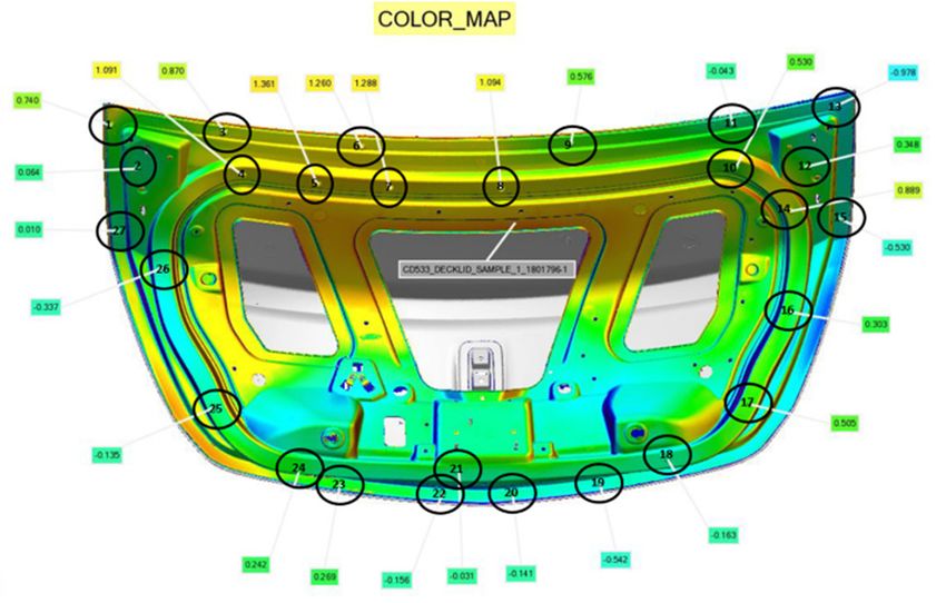
SMC, VORAFUSE™ M6400. The intent of the project team was to deliver industrially relevant
composite technology, advanced processing and tooling required to commoditize the processing
of light weight components. From a vehicle production volume perspective, this represents a
departure from material formats commonly used in low volume niche market applications.
Instead, the project team was focused on developing a material system that could accommodate
vehicle volumes around 100k/yr, leveraging infrastructure already in position within the Tier 1
supply base.

                                       Figure 1. Fuel economy trends

Figure 2: Mandated change in vehicle CO2 emissions as measured during the New European Drive Cycle (NEDC) as
                                measured in grams of CO2 per kilometer of travel.

                                                                 ™ Trademark of The Dow Chemical Company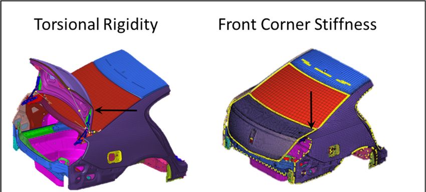
Figure 3: Trends in vehicle mass for the North American car and truck market.

                              Material & Process Development
Critical to Quality Requirements (CTQ’s)
   To ensure development of high performance composite materials, ready for high volume
manufacturing, detailed Critical-to-Quality (CTQ) metrics were established for processing speed,
molded part Tg, and mechanical performance. A few relevant CTQ’s are shown in Table I.

    A key CTQ for the CF-SMC is a cured Tg higher than the cure temperature when cured for
two minutes at ~150 °C. A Tg >150 °C allows a part, compression molded at around 150 °C, to
be released while still hot without warping. That is, it enables parts to have sufficient integrity to
be de-molded without first cooling the mold and part, which in turn enables shorter molding cycle
times. In addition, a Tg >150 °C provides a composite material with the property of high heat
distortion temperature which is needed for demanding applications.

                           Table I. Key processing/property requirements

  Process/Property                           Required performance
  SMC storage stability                      50 days at ≤ 40 °C
  Molding                                    Compression molding
  Mold temperature                           145 -155 °C
  # of parts molded between
  applications of external mold              1000
  release
  Cure speed (resin cure kinetics)           < 2 min @ 150 °C (DSC)
  Degree of cure after molding               > 95%
  Cured Tg                                   150 – 160 °C (DMA)

   From a processing perspective, maintaining a cycle time of 3 minutes per part with 1000 parts
molded between applications of an external mold release, is essential for uninterrupted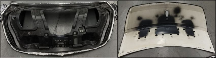
production. Epoxy polymers, being excellent adhesives, bond tenaciously to metals making it
necessary to utilize a release agent so that parts can be quickly and easily removed from the
metal mold without damage or distortion. Internal mold release agents are preferred because they
eliminate the need for frequent application of the release agent to the mold, thereby increasing
productivity and reducing part cost. Hence, the CF-SMC formulation developed featured an
internal mold release system that achieved the desired mold release characteristics while also
providing capability for subsequent bonding and painting.

Novel CF-SMC for Compression Molding
    The CF-SMC system developed is based on an epoxy resin formulation designed to be
compatible with e-coat process for the vehicle body in white. In practice, this means tolerating
the thermal exposure during the e-coating and paint processes. The use of carbon fiber as the
polymer reinforcement increases stiffness by approximately three fold over glass based SMC
products, while also offering substantial improvement in strength. Figure 4 demonstrates the
targets of strength and stiffness for material development.

                       Figure 4. Market for modulus vs strength for SMC systems.

The key challenges for meeting these targets:
   • Achieving strength and stiffness while allowing material to flow during the compression
      molding cycle to create complex 3D geometry
   • Infusing the carbon fiber to reduce voids in a high volume production rate
   • Defining a repeatable fiber aspect ratio to achieve predictable performance

    The aspect ratio of the carbon fiber control both molding flow characteristics and final part
strength. Determining the window of fiber aspect ratio providing strength and modulus in the
target range, as well as providing enough flow during compression molding to create the complex
3D part geometry in high volume production processes was key to the success of this
development. For example, a fiber aspect ratio (defined as length/width) of 100 may provide
excellent physical properties, but near zero flow. The zero flow material may be useful in low
production volume, simple geometry parts, however these designs were not the target of this
development. Table II provides a summary of key physical properties for samples extracted from
molded flat plaques. Subsequent validation work for material processing and performance of the
CF-SMC material was completed with a material system L/W equal to 17.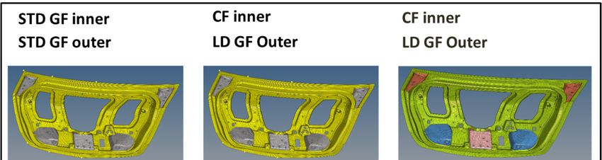
Table II: Representative properties for Novel Carbon Fiber SMC

Material Validation & Testing
    To validate the performance of the new carbon fiber SMC system, a rear closure was selected
for re-design using the CF-SMC material. Target CTQs were used as input into engineering
analysis to develop a final design for comparison against the incumbent material system. Figure
4 shows the vehicle selected for this study, a Lincoln MKS, with the corresponding decklid
assembly.

                               Figure 4: Lincoln MKS with decklid assembly

            Figure 5. Comparison of production vs. prototype carbon fiber SMC decklid assembly

    As Figure 5 indicates, the production release version of the decklid was manufactured from a
glass fiber SMC inner and outer combination. Localized steel reinforcements were attached to
the inner panel to provide attachment locations for the hinges and latch, with common hardware
and reinforcements for all design variants. For the case of the non-production, re-designed
decklid, CF-SMC was selected for the inner panel material, in combination with a low density
glass fiber SMC outer panel. The transition from a 1.9 g/cm3 standard density outer to a 1.3
g/cm3Error! Not a valid bookmark self-reference. low density outer, providing additional
opportunity for reduction in overall assembly mass.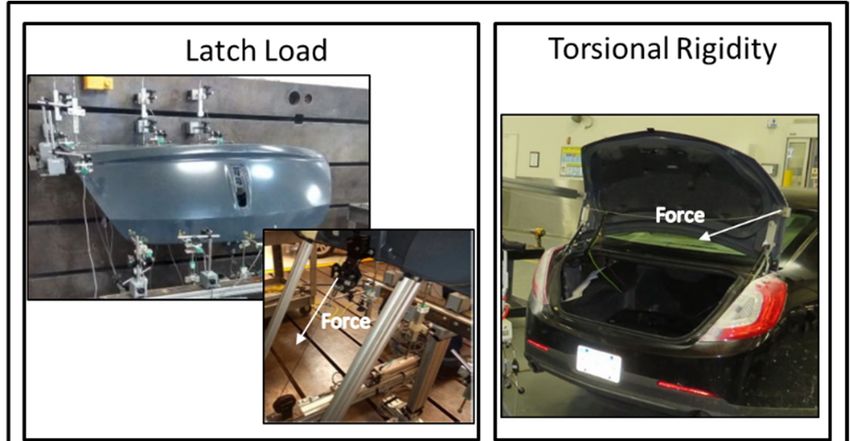
Figure 6: Lincoln MKS decklid base-line design in comparison to a carbon fiber inner / glass fiber outer concept.

    To guide the design and development of the carbon/glass hybrid decklid, a series of key load
cases were selected to assess overall function versus the baseline design. CAE representations
of these load cases are shown in Figures 6. While it should be noted that these load cases are
only a sub-set of analysis performed as part of a regular vehicle production program, the analysis
can still be used to project the estimated weight savings potential and performance against the
incumbent. For the selected load cases, the carbon/glass hybrid design was able to take full
advantage of the increase in intrinsic stiffness. Specifically, combining the existing inner panel
geometry with a threefold increase in modulus for the carbon fiber translated to a significant
improvement in overall performance of the decklid assembly.
     A summary of predicted performance versus the baseline production decklid is shown in Table
III. In terms of a test response, a reduction in deflection for each load case is shown as a
percentage improvement. All four tests outperformed the baseline by significant margins,
providing considerable potential for design optimization. Subsequent design studies focused on
topology optimization assumed a minimum gage thickness of 2.0mm. While flat plaque and small
part molding studies had previously demonstrated flow down to 1.5mm, a more conservative
approach was taken for the decklid due to the size and shape complexity.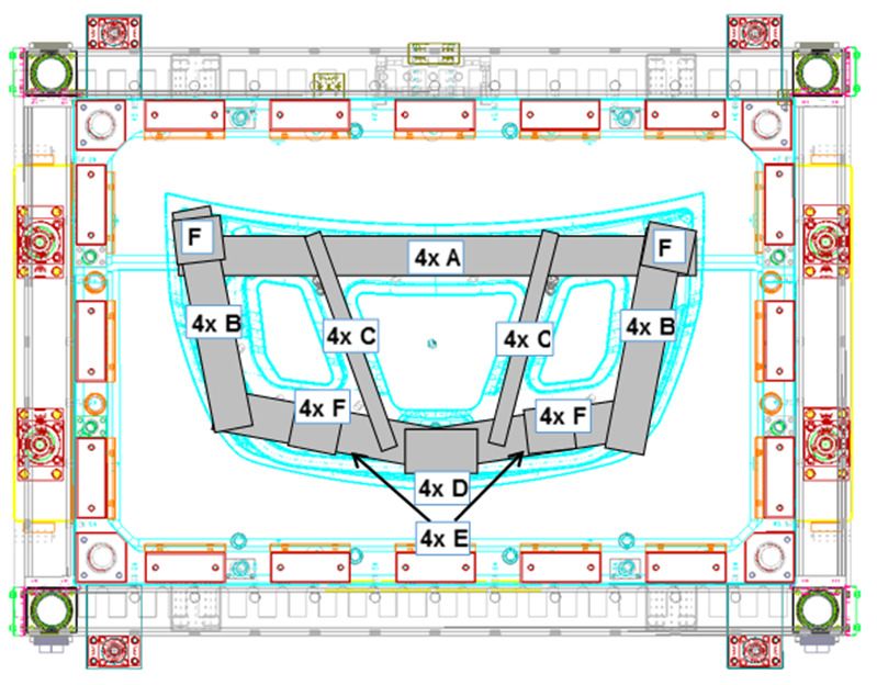
Table III: Comparison of carbon fiber hybrid decklid design to baseline performance.
Baseline vs
Baseline vs CF Pass/
Test Result units Optimized CF
SMC Fail
SMC
Front
Corner Displacement -Z (mm) 35.8% 28.3% Pass
Deflection
Waterfall
Displacement Z (mm) 47.5% 24.0% Pass
Deflection
Displacement Normal
Latch Loads 45.6% 36.3% Pass
to Surf. (mm)
Torsional Angle / meter
55.0% 30.5% Pass
Rigidity (degrees/m)
The mass of the baseline design and carbon/glass hybrids is shown in Figure 7. As expected,
the assembly mass reduces, initially due to a straight density change, followed by optimization of
part thickness. On the left-hand side of the figure, the inner and outer panel mass for the
production release decklid is listed as 10.5kg. A straight substitution of the inner panel with a
carbon fiber SMC and outer panel to the LD-SMC, reduces the mass by 3.17kg. Further
optimization of panel thickness within the limits of manufacturing feasibility resulted in a final
design weight of 6.81 kg. It should be noted that following design optimization, confirmation of
performance was established through physical testing of prototype components, as is described
later.
Figure 7. Comparison of decklid masses for baseline and carbon/glass hybrid designs.
Prototype Production
For prototyping activities, carbon fiber SMC decklid inners and low density glass fiber SMC
outers were manufactured using series production compression molding tools. For the carbon
fiber SMC decklid inner, an initial charge pattern was developed based upon the production glass
fiber SMC and then modified to account for the lower carbon fiber SMC areal density and material
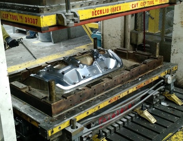
distribution in various regions of the component (Figures 8 and 9).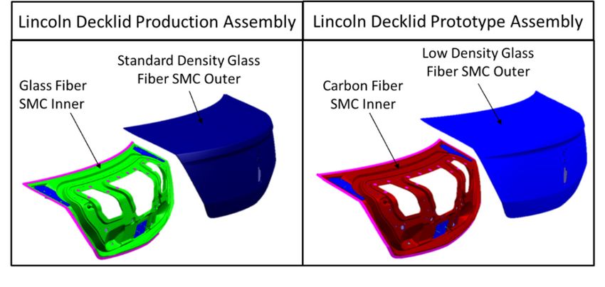
Figures 8 and 9. Decklid inner charge pattern and Lincoln MKS decklid inner molding tool.

    A standard tool closure profile combined with a mold temperature of 150 °C resulted in a
component cure time of less than 3 minutes. Clamp tonnage on the compression press was also
typical for SMC processing at approximately 1500 psi (~100 Bar). Incorporation of an internal
mold release agent within the epoxy matrix also eliminated the need for coating the production
steel tooling. Following part ejection, decklid inners were placed on cooling fixture ahead of de-
flashing and trimming in preparation for assembly.

                                Figure 10. Bill of Process for Decklid Assembly
    Decklid assemblies, comprised of low density glass fiber SMC outers and carbon fiber SMC
inner panels, were fabricated per the bill of process given below in Figure 10. Localized steel
reinforcements at the hinge and latch areas were attached using blind rivets and a structural
adhesive. The decklid inner and outer were joined using the same structural adhesive. For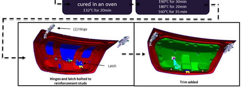
prototype assemblies, the two component adhesive was cured at room temperature prior to the
assembly being subjected to the standard paint process including all oven cure cycles (conductive
primer, e-coat, primer, paint). Following the paint cycles, the latch and hinges were installed along
with interior trim items.

Design Verification Testing
    Prior to any formal verification studies, a series of assembly teardowns was completed to
ensure adequate adhesion of the structural adhesive to the carbon fiber inner and a continuous
bond along the perimeter. Figure 11 show an example inner panel and corresponding low density
SMC outer. It should be noted that throughout the bond line, the adhesive bond strength is shown
to be sufficient to promote fiber tear out of the outer panel around the entire perimeter. This is
confirmation of good adhesion between the inner and outer as no evidence of cohesive failure or
adhesive failure to the inner was present.

          Figure 11. Decklid assembly teardown for validation of adhesive placement and bond strength

                          Figure 12. Physical testing of prototype decklid assemblies.
Following the teardown study, physical testing of decklid assemblies was performed to verify
performance versus requirements. Figures 12 shows the physical representation of the load
cases described as part of the CAE design optimization process above. As is observed, the latch
pull and waterfall deflection test were performed at the component level, whereas the front corner
deflection and torsional rigidity were performed on vehicle. Per the CAE predictions, the
carbon/glass hybrid design was observed to be stiffer than the production version of the decklid
(Table IV). This resulted in lower displacement, far exceeding requirements for each of the load
cases.
Table IV. Pass/Fail results for prototype decklid physical testing
Manufacturing Robustness
As an initial evaluation of manufacturing robustness, an assembly dimensional study was
performed for a small (n=5) sample of prototype parts. The intent was to understand repeatability
of both the molding and bonding assembly process. Figure 14 shows a dimensional map of 3D
scanned parts compared to engineering CAD data. The standard deviation, point to point, shows
a consistent trend, part to part. The largest deviation from nominal appeared to be at the leading
upper edge of the decklid, at a mid-point between the hinges. However, this is not surprising as
these points are the furthest from any mounting locations. While it was not within the scope of
this exercise, it is anticipated that improvements in dimensions could be achieved through charge
placement development and revisions to the cooling fixtures.
Interval Plot of Loc 1, Loc 2, Loc 3, Loc 4, Loc 5, Loc 6, Loc 7, ...
95% CI for the Mean
3
2
1
Data
0
-1
-2
1 7 1 7 18 19 0 21 2 3 4 7
c c 2 c 3 c 4 c 5 c 6 c c 8 c 9 10 c 1 12 13 14 15 16 1 2 2 2 2 2 5 26 2
Lo L o Lo L o L o Lo Lo L o L o Lo c Lo Loc Lo c L oc L oc Loc Loc L oc Loc oc L oc o c oc oc o c oc oc
L L L L L L L
Individual standard deviations are used to calculate the intervals.
Figure 14. Dimensional variation of prototype decklid assemblies (n=5)Summary and Conclusions
The on-going drive for improvements in vehicle fuel economy continues to spur new
innovations in a wide array of vehicle technologies with vehicle mass reduction considered a
critical element to achieving this goal. The latter has prompted renewed interest in lightweight
body systems that take advantage of advances in materials such as high strength steel, light
metals and composites. This report summarized a joint project undertaken through the Institute
for Advanced Composites Manufacturing Innovation. The project partners consisted of Dow
Automotive, Ford, DowAksa, Purdue, University of Tennessee, Michigan State and Oak Ridge
National Lab. Research was focused on the development of a carbon fiber material system that
could be adopted to support high volume manufacturing. A result of this joint development has
yielded an epoxy based SMC that features room temperature shelf stable technology and a
threefold increase in modulus compared to comparable glass based products. Following,
laboratory prove-out, operations were scaled to enabled large part molding and component
assembly. Subsequently, decklid assemblies were subjected to validation testing to confirm
performance against original design predictions.
Acknowledgements
The authors acknowledge the assistance of the Research and Innovation Team at Ford, the
Corporate R&D team at Dow and the R&D team at DowAksa for their unrelenting commitment to
this project. Furthermore, funding in support of this project was provided by the US Department
of Energy, the states of Michigan, Indiana and Tennessee through a project executed through the
Institute of Advanced Composites Manufacturing Innovation.
References
1. Fuel Economy and Mass Trends, US Environmental Protection Agency Report, 2017
2. Ford Motor Company. Ford Sustainability Report 2014/15.You can also read