CHICAGO O'HARE INTERNATIONAL AIRPORT - ADVANCED AIRFIELD FAMILIARIZATION MANUAL 14 CFR PART 139.329 - Flychicago
←
→
Page content transcription
If your browser does not render page correctly, please read the page content below
CHICAGO O’HARE INTERNATIONAL AIRPORT

                ADVANCED
         AIRFIELD FAMILIARIZATION
                 MANUAL

           14 CFR PART 139.329

                PREPARED BY
              CITY OF CHICAGO
          DEPARTMENT OF AVIATION
            AIRFIELD OPERATIONS

                  Revision
                 202106/01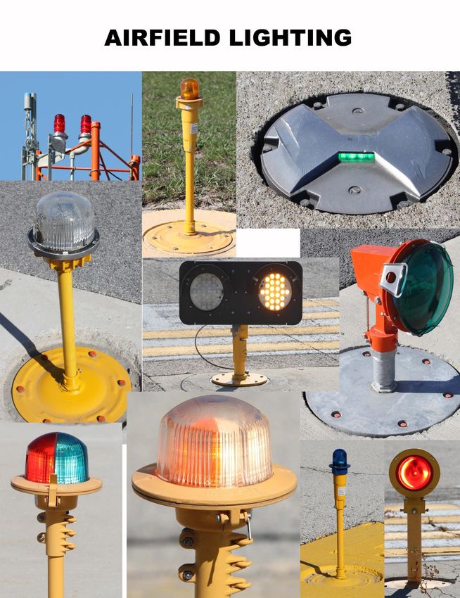
TABLE OF CONTENTS

Summary of Changes ............................................................................................... 6
Introduction ............................................................................................................... 9
    CDA Address ....................................................................................................... 9
    Airfield Operations Phone Numbers.................................................................... 9
    O’Hare Communication Center Phone Numbers ................................................ 9
Phonetic Alphabet ................................................................................................. 10
Facilities Familiarization .......................................................................................... 11
     ARFF (Rescue Stations) ................................................................................... 11
     Gates ................................................................................................................ 11
     Cargo Facilities ................................................................................................. 16
Airfield Markings .................................................................................................... 17
     Runway Markings ............................................................................................ 18
        Marking Color ............................................................................................... 18
        Runway Designators ..................................................................................... 18
        Runway Use Information................................................................................ 19
        Runway Lengths and Widths ......................................................................... 19
        Airport Reference Point.................................................................................. 20
        Runway Centerline Marking .......................................................................... 21
        Runway Aiming Point Marking ...................................................................... 21
        Runway Touchdown Zone Markers .............................................................. 21
        Runway Side Stripe Marking ......................................................................... 21
        Runway Shoulder Marking ............................................................................ 21
        Runway Threshold Marking .......................................................................... 22
        Relocated Threshold Marking ....................................................................... 22
        Runway Displaced Threshold Marking .......................................................... 22
                                                              1
Demarcation Bar ........................................................................................ 23
            Chevrons .................................................................................................. 23
        Closed Runways and Taxiways .................................................................... 24
     Taxiway Markings ............................................................................................. 25
        General ........................................................................................................ 25
        Non-Movement Area Boundary Marking ....................................................... 25
        Taxiway Centerline Marking .......................................................................... 25
        Enhanced Taxiway Centerline Marking ......................................................... 26
        Taxiway Edge Markings ................................................................................ 26
        Geographic Position Markings………………………………………………….... 27
        Taxiway Shoulder Markings ......................................................................... 27
        Surface Painted Taxiway Direction Signs ..................................................... 28
        Surface Painted Taxiway Location Signs ...................................................... 28
        Runway Holding Position Markings ................................................................ 29
        Surface Painted Runway Holding Position Sign ........................................... 29
        ILS Holding Position Marking ........................................................................ 30
        Taxiway/Taxiway Intersection Intermediate Holding Position ........................ 30
     Roadway Markings ........................................................................................... 31
         Roadways .................................................................................................... 31
         Runway Safety Area Signs .......................................................................... 32
         Taxiway Object Free Area Pavement Markings For B747-8 & A380 ............ 33
Airfield Signs........................................................................................................... 34
   Runway and Taxiway Guidance Signs ............................................................... 35
   General Information on Taxiway Designations ................................................... 35
   Taxiway/Runway Intersection ............................................................................ 36
   Runway/Runway Intersection ........................................................................... 37

                                                             2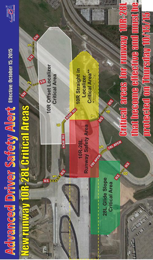
Instrument Landing System Critical Areas ......................................................... 37
   No Entry Areas .................................................................................................. 37
   Runway Approach Areas ................................................................................... 37
   Cat II/III Operations Areas ................................................................................. 38
    Runway Safety Area Holding Position Signs ..................................................... 38
    Directional Sign ................................................................................................ 38
    Location Signs .................................................................................................. 39
        Taxiway Location Sign .................................................................................. 39
        Runway Location Sign .................................................................................. 39
    Runway Approach Boundary Sign .................................................................... 39
    ILS Critical Area/POFZ Boundary and Cat II/III Operations Sign....................... 40
    Runway Distance Remaining Sign .................................................................... 40
    Taxiway End Marker ........................................................................................ 40
    Destination Signs .............................................................................................. 41
    Information Signs .............................................................................................. 41
Airfield Lighting ....................................................................................................... 42
    Runway Edge Lights ......................................................................................... 43
    Touchdown Zone Lighting................................................................................. 43
    Runway Centerline Lighting .............................................................................. 43
   Threshold/Runway End Lights ........................................................................... 44
   Taxiway Centerline Lights .................................................................................. 44
   Taxiway Lead-on/Lead-off Lights ....................................................................... 44
   Land and Hold Short Lights (LAHSO) ............................................................... 45
   Taxiway Edge Lights.......................................................................................... 45
   Runway Guard Lights ....................................................................................... 45
   Stop Bars .......................................................................................................... 46

                                                             3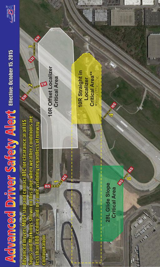
Obstruction Lights ............................................................................................. 46
   Wind Cones ...................................................................................................... 46
   Airport Rotating Beacon .................................................................................... 47
Runway Status Lights ............................................................................................. 48
    Runway Entrance Lights ................................................................................... 48
    Takeoff Hold Lights .......................................................................................... 48
Runway Status Lights Vehicle Procedures ............................................................ 49
ATCT Light Gun Signals ………………………………………………………………....49
FAA Navigational Aids ............................................................................................ 50
     Approach Lighting System (ALS) ..................................................................... 50
     FAA Threshold Lights ...................................................................................... 50
     Precision Approach Path Indicators (Papi’s) ................................................... 51
     Instrument Landing System (ILS) .................................................................... 51
         Localizer ..................................................................................................... 51
         Glideslope................................................................................................... 52
         DVOR/DME ................................................................................................ 52
         DME ............................................................................................................ 52
     Low-Level Windshear Alert System (LLWAS) ................................................. 53
Air Traffic Control Radio Phraseology ..................................................................... 54
ATCT Radio Communication Procedures .............................................................. 55
Effective Communication ....................................................................................... 55
Taxi Instructions for the Northeast Cargo Ramp .................................................... 60
          Advanced Driver Safety Alert ..................................................................... 61
     ORD AOA Safety Alert ..................................................................................... 63
Operation of Ground Vehicles ................................................................................ 65
     Runways .......................................................................................................... 65

                                                            4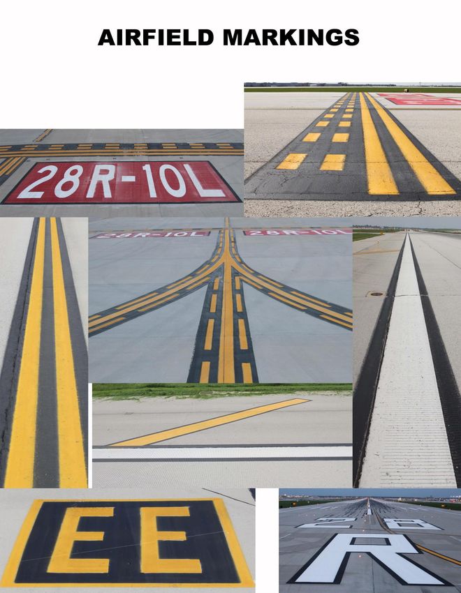
Movement Area ............................................................................................... 65
     Operations Near Aircraft .................................................................................. 66
Aircraft Repositioning.............................................................................................. 66
Noise Abatement Runway Closures Advisory ......................................................... 66
Lessons Learned .................................................................................................... 67
Things Change ...................................................................................................... 68
Airport Sign and Marking Quick Reference Guide................................................... 69

                                                          5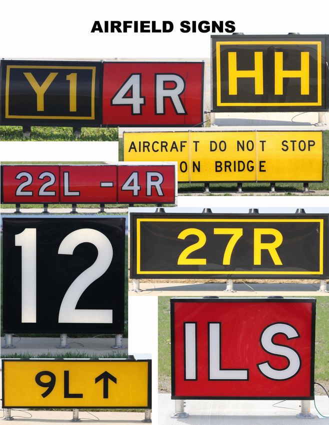
Summary of Changes

Revision 201703/01    1. All graphics pertaining to nomenclature moved to supplement packet.
                      2. Content Revision – MANDATORY INSTRUCTION SIGNS
                      3. Content Addition – NON-MOVEMENT AREA BOUNDARY MARKING
Revision 201706/01    1. Content Revision – TAXIWAY SHOULDER MARKINGS – Picture Update
Revision 201711/01    1. Content Revision – Rescue 2 & Rescue 4 locations following taxiway
                      changes
Revision 201804/01   1. Content Change – Air Traffic Control Radio Phraseology
                     2. Content Change – ATCT Radio Communication Procedures
                     3. Content Change – Effective Communication
Revision 201807/01   1. Content Addition – Taxi Instructions for the Northeast Cargo Ramp
Revision 201809/01   1. Content Revision – Instrument Landing System (ILS) Critical Areas
                     2. Content Change – opsdocs web address
Revision 202009/02   1. Content Revision – Rescue 2 location change
Revision 202011/01   1. Content Addition – Information regarding RWY 9C-27C
Revision 202012/01   1. Content Change – Corrected general information errors
Revision 202104/01   1. Content Change – Removed AOA Alert
Revision 202106/01   1. Content Revision – ATC RADIO COMMUNICATION PROCEDURES

                                           6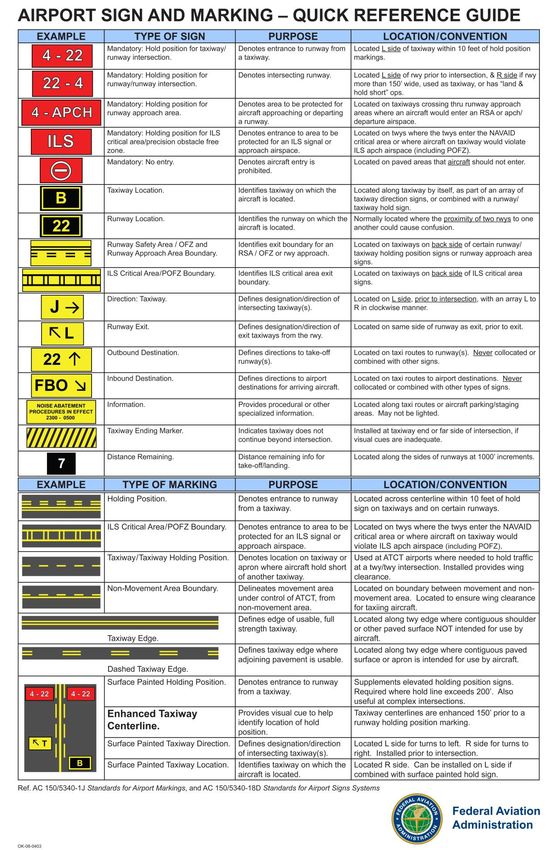
INTENTIONALLY LEFT BLANK

           7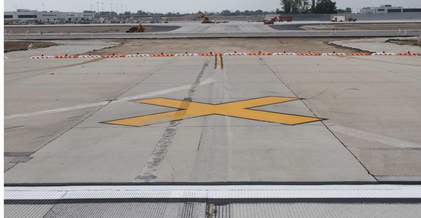
INTENTIONALLY LEFT BLANK

           8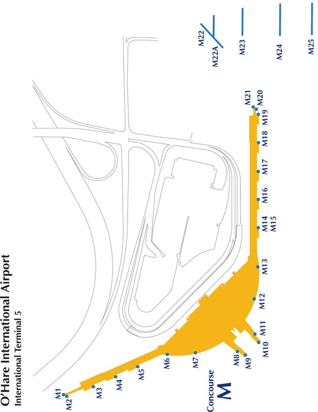
INTRODUCTION

This Manual was developed by the City of Chicago, Department of Aviation, Airport Airfield Operations
Section (AAO). Its purpose is to implement training requirements mandated by 14 CFR 139.329, and to
review important safety information relating to personnel who operate vehicles, equipment, and taxi aircraft
in the movement area - runways, taxiways, and surrounding surfaces. This will enable you to understand
the hazards and the controls created for your protection and for the safety of others at O’Hare International
Airport. It is the responsibility of each person who works in or around the movement area to study and
understand this information.

                                O’HARE INTERNATIONAL AIRPORT
                               CHICAGO DEPARTMENT OF AVIATION
                                     10510 W. ZEMKE ROAD

                                             P.O. BOX 66142

                                      CHICAGO, ILLINOIS 60666

                                        AIRFIELD OPERATIONS
                                             CITY ATRIUM
                                            P.773.686.2255

                                O’HARE COMMUNICATIONS CENTER

                                    EMERGENCIES – 773.894.9111

                                NON-EMERGENCIES – 773.894.5000

                                                     9
PHONETIC ALPHABET
Character Telephony Pronunciation Character Telephony Pronunciation
A Alfa (AL-FAH) N November (NO-VEM-BER)
B Bravo (BRAH-VOH) O Oscar (OSS-CAH)
C Charlie (CHAR-LEE) P Papa (PAH-PAH)
D Delta (DELL-TA) Q Quebec (KEH-BECK)
E Echo (ECK-OH) R Romeo (ROW-ME-OH)
F Foxtrot (FOKS-TROT) S Sierra (SEE-AIR-RAH)
G Golf (GOLF) T Tango (TANG-GO)
H Hotel (HOH-TEL) U Uniform (YOU-NEE-FORM)
I India (IN-DEE-AH) V Victor (VIK-TAH)
J Juliett (JEW-LEE-ETT) W Whiskey (WIS-KEY)
K Kilo (KEY-LOH) X X-ray (ECKS-RAY)
L Lima (LEE-MAH) Y Yankee (YANG-KEY)
M Mike (MIKE) Z Zulu (ZOO-LOO)
Character Telephony Pronunciation Character Telephony Pronunciation
1 One (WUN) 6 Six (SIX)
2 Two (TOO) 7 Seven (SEV-EN)
3 Three (TREE) 8 Eight (AIT)
4 Four (FOW-ER) 9 Nine (NIN-ER)
5 Five (FIFE) 0 Zero (ZEE-RO)
* NOTE *
When referencing a RUNWAY DESIGNATION - numbers are spoken in single digits between 0 and 9.
When combining two number characters to say a runway you would speak a single digit, followed by a
single digit. For example, Runway 10L would be spoken Runway One-Zero Left, NOT Runway Ten
Left.
10FACILITIES FAMILIARIZATION
Concentrations of buildings on the airport consist of the “core” or Domestic Terminal Complex, International
Terminal Complex, the Hangar Alley to the north, the cargo area to the Southwest and Southeast, the
Airport Maintenance Complex (AMC) to the Southeast and the Northeast Ramp to the Northeast.
The airport is also divided into landside operations and airside operations. The landside portion includes
all terminal areas, access roads and the Kennedy (I-190) Expressway to Mannheim Road. The security
checkpoints referred to as “Guard posts” provide access to the airside portion, where all air traffic
movements take place.
AIRCRAFT RESCUE AND FIRE FIGHTING STATIONS
Chicago O’Hare International Airport has four (4) Aircraft Rescue and Fire Fighting (ARFF) or rescue
stations strategically located on airport property, three stations airside and one landside. O’Hare is ARFF
index E.
1. Rescue 1 is located on the south side of the airfield just Northwest of TWY S1
2. Rescue 2 is located on the North side of the airfield at the intersection of TWY M and TWY D
3. Rescue 3 (District 3 headquarters) is located landside, in the terminal core area off of the
recirculation route just past Terminal 3
4. Rescue 4 is located on the North side of the airfield at the intersection of TWY C and TWY C PAD
GATES
In this section the trainee will be exposed to the various ramp areas on the airfield, including all gates at
various concourses, and their number system as an identification method to locate a certain gate. There
are a total of 188 gate positions at O’Hare International Airport (ORD) which include all four (4) airline
passenger terminals.
1112
13
14
15
CARGO FACILITIES

Northeast Cargo is located South of the Runway 22R APCH. The buildings include: AGI, Swissport, TAS

Southwest Cargo is located South of Runway 10C-28C at Taxiway BB.
FedEx is the only cargo carrier at this location.

South Central Cargo is located South of Runway 10C-28C, East end of Taxiway Q and South end of
Taxiway DD. United Cargo Building is the only cargo carrier at this location – leasing space to AeroUnion,
British Airways, CargoLux, Cathay Pacific, Justice, Kalitta Air,

Southeast Cargo is located West of Taxiways S-1, S-2.
The buildings include: Air France Cargo, American Airlines Cargo, Delta Cargo, Federal Express (second
facility), KLM Cargo, Lufthansa Cargo, Nippon Cargo, and United Parcel Service.

Chicago O’Hare Express Center: The newest facility is located directly south of the AMC Building at the
corner of Mannheim and Irving Park Road. The buildings to date include: Aer Lingus, Burlington Air
Freight, Air Canada, Japan Airlines, British Airways, Cathay Pacific, Alliance, Korean Air, Challenge, Varig,
Fin Air, Virgin Atlantic, Turkish Airlines, Lot Polish, Iberia, Eva, Midwest Express, Harjin, Saudi Arabian
Airlines, Air New Zealand, Air Jordan, Shanghai Airlines Cargo, Singapore Airlines Cargo, China Southern,
Air General, Polar Air Cargo, Swissport

                                                     16
17
RUNWAY MARKINGS
MARKING COLOR
All runway markings are white in color and outlined in black.
                           ***** EXCEPTION TO THE RULE *****
Runway intersection hold short markings, taxiways lead in / lead out lines that
extend onto the runway, and runway shoulder markings (chevrons) are yellow in
color.
RUNWAY DESIGNATORS

- They are white in color and consist of a single
digit number or two numbers and may be
supplemented with a letter -

The runway landing designator marking identifies a
runway end located near the runway threshold.

Types of single, dual parallel, and triple parallel
runway designators:

   1) A single-digit runway landing designation
      number is never preceded by a zero.

   2) The designator number is the whole number
      nearest the one-tenth of the magnetic
      azimuth along the runway centerline when
      viewed from the direction of approach. For
                                                              ↑           ↑            ↑
      example, where the magnetic azimuth along           “L” – indicates a “LEFT” designation
      the runway centerline is 273 degrees, the
      runway designator marking would be 27.             “C” – indicates a “CENTER” designation
   3) Two parallel runways having a magnetic              “R” – indicates a “RIGHT” designation
      azimuth of 270-279 degrees – the runways
      would be designated “27L,” “27R.”

   4) Five parallel runways having a magnetic
      azimuth of 270-279 degrees – the runways         ***THE 6 EAST/WEST PARALLELS***
      would be designated “27L,” “27R,” “28L,”
                                                        RUNWAYS ON THE NORTH AIRFIELD:
      “28C,” “28R” or “28L,” “28R,” “27L,” “27C,”
      “27R.”                                                9L-27R / 9C-27C / 9R-27L

   5) Six parallel runways having a magnetic            RUNWAYS ON THE SOUTH AIRFIELD:
      azimuth of 90-99 degrees – the runways               10L-28R / 10C-28C / 10R-28L
      would be designated “9L,” “9C,” “9R,” “10L,”
      “10C,” “10R” or “28L,” “28C,” “28R,” “27L,”
      “27C,” “27R.” → → → → → → → → → →

                                                  18
RUNWAY USE INFORMATION
Runways are identified by their magnetic compass headings. For example, runway 9L-27R is positioned
directly East and West. East is 090 degrees and West is 270 degrees, thus the runway is identified as ‘9L-
27R’. The third digit is just dropped from the magnetic heading. The ‘L’ and ‘R’ refer to left and right,
indicating there are one or more parallel runway(s) with the same compass heading. The ‘L’ indicates that
this is the LEFT parallel runway while the opposite is true for the ‘R’ designator. A runway with a ‘C’
indicates there are more than 2 parallel runways with the same magnetic heading.
All references to runways should be made in the direction the aircraft are heading. The figure below is a
depiction of a compass rose with runway 4L-22R super-imposed on the diagram.
North Airfield RWY Lengths & Widths South Airfield RWY Lengths & Widths
4L-22R – 7,500’ x 150’ 4R-22L – 8,075’ X 150’
9L-27R – 7,500’ X 150’ 10L-28R – 13,001’ X 150’
9C-27C – 11,245’ X 200’ 10C-28C – 10,801’ X 200’
9R-27L – 7,967’ X 150’ 10R-28L – 7,500’ X 150’
19AIRPORT REFERENCE POINT
The airport reference point (ARP) geographically
locates the airport horizontally. The ARP is normally
not monumented or physically marked on the
ground. The computation of this point uses only
runway length, and do not use closed or abandoned
areas. The ARP is computed or recomputed as
infrequently as possible. The only time that a
recomputation is needed is when the proposed
ultimate development is changed.
ARP Coordinates
Latitude N 41º 58’ 38.35”
Longitude W 087º 54’ 28.82”
Airport Elevation: 680’
20RUNWAY CENTERLINE MARKING
- Are white in color and consist of uniformly
spaced stripes and gaps and run the entire length
of the runway between landing designation
markings -
The runway centerline marking identifies the physical
center of the runway width. It provides alignment
guidance to pilots during takeoff and landing
operations.
RUNWAY AIMING POINT MARKING
* NOTE *
- Two rectangular markings consisting of a broad white stripe –
Can be used for
The aiming point marking serves as a visual aiming point for landing aircraft distance remaining
and are located on each side of the runway centerline and approximately information
1,000 feet from the runway threshold.
RUNWAY TOUCHDOWN ZONE MARKERS
- The markings consist of symmetrically arranged pairs of white rectangular bars in groups of one,
two, and three along the runway centerline -
The touchdown zone marking is a visual aid for landing aircraft that identifies the touchdown zone along a
runway in 500 foot increments.
RUNWAY SIDE STRIPE MARKING
- Runway side stripe marking are white and consist
of two parallel stripes, one placed along each edge of
the usable runway -
The runway side stripe marking provides enhanced
visual contrast between the runway edge and the
surrounding terrain or runway shoulders and delineates
the width of suitable paved area for runway operations.
RUNWAY SHOULDER MARKING
- Runway shoulder markings are yellow and located
between the runway side stripe and the outer edge of
the paved shoulder -
The runway shoulder marking is used as a supplement to
* NOTE *
further delineate a paved runway shoulder that is likely to Can be used for distance remaining
be mistaken as usable runway. This marking is used only information – change direction in center of
in conjunction with the runway side stripe marking. runway
21RUNWAY THRESHOLD MARKINGS
- They are white in color and consist of a pattern of longitudinal stripes spaced symmetrically
about the runway centerline -
A runway threshold marking identifies the actual beginning point of the runway used for landings.
RELOCATED THRESHOLD
Sometimes construction, maintenance, obstructions to navigational aids, or other activities require the
threshold to be relocated towards the rollout end of the runway. When a threshold is relocated, it closes not
only a set portion of the approach end of a runway, but also shortens the length of the opposite direction
runway.
RUNWAY DISPLACED THRESHOLD MARKING
A threshold that is located at a point on the runway other than the beginning. This area may be available
for takeoffs in either direction and landings from the opposite direction.
Runway Threshold Bar Marking
- The runway threshold bar marking is white and is an elongated rectangular bar that is located
perpendicular to the runway centerline and on the landing portion of the runway –
The runway threshold bar marking delineates the beginning section of the runway available for landing
from the unusable section on the approach side of the displaced threshold. The predominant case is when
the threshold is displaced from the runway end. In this case white arrowheads with and without arrow
shafts are required to identify the portion of the runway before the displaced threshold to provide
centerline guidance for: 1) ground vehicles, 2) taxiing, and 3) pilots during: 1) approaches, 2) takeoffs, and
3) landing rollouts from the opposite direction.
22DEMARCATION BAR
- A demarcation bar is a 3 feet wide yellow elongated rectangular bar on a blast pad, stopway, or an
aligned taxiway that is perpendicular to the runway centerline at the point of intersection with the
start of the runway -
A demarcation bar delineates a runway with a displaced threshold from a blast pad, stopway, or an aligned
taxiway that precedes the runway.
CHEVRONS
- Chevron markings are yellow and located on the blast pad and stopway that are aligned with and
contiguous to the runway end. The chevron scheme for an EMAS installation is also centered along
the extended runway centerline -
The chevron marking identifies paved blast pads, stopways, and EMAS (engineered materials arresting
systems) in relation to the end of the runway.
Blast pads equal the runway width
plus the shoulder widths
23CLOSED RUNWAYS AND TAXIWAYS
PERMANENTLY CLOSED RUNWAYS AND TAXIWAYS
For runways and taxiways which are permanently closed, the lighting circuits will be disconnected. The
runway threshold, runway designation, and touchdown markings are obliterated and yellow crosses – “X’s”
– are placed at each end of the runway and at 1,000 foot intervals
TEMPORARILY CLOSED RUNWAYS AND TAXIWAYS
To provide a visual indication to pilots/ground vehicles that a runway is temporarily closed, crosses – “X’s”
– are placed on the runway only at each end of the runway. The crosses are yellow in color.
1) A raised lighted yellow cross – “X” – may be placed on each runway end in lieu of the markings to
indicate the runway is closed.
2) A visual indication may not be present depending on the reason for the closure, duration of the
closure, airfield configuration and the existence and the hours of operation of an airport traffic
control tower. Pilots/ground vehicles/taxi mechanics should check NOTAMs and the Automated
Terminal Information System (ATIS – 135.40MHz) for local runway and taxiway closure information.
3) Temporarily closed taxiways are usually treated as hazardous areas, in which no part of an
aircraft may enter, and are blocked with barricades. However, as an alternative a yellow
cross may be installed at each entrance to the taxiway.
24TAXIWAY MARKINGS
GENERAL
All taxiways regardless of their width have a centerline marking,
and whenever a taxiway intersects a runway, the taxiway will
have a surface painted runway holding position marking.
NON-MOVEMENT AREA BOUNDAY MARKING
- The non-movement area boundary marking consists of
two yellow lines, one solid and one dashed. The solid line is
located on the side of the non-movement area while the
dashed line is located on the side of the movement area.
Each line is 6 inches in width with 6-inch spacing between
lines. The dashes are 3 feet in length with 3-foot spacing
between dashes. -
The non-movement area boundary marking is used to delineate
the movement areas under direct control by the airport traffic
control tower from the non-movement areas that are not under
their control.
TAXIWAY CENTERLINE MARKING
- A single continuous yellow line with black borders on
either side of the yellow line -
All taxiways regardless of their width have a surface painted
taxiway centerline that provides pilots or ground vehicles visual
guidance to permit taxiing along a designated path. On straight
sections of a taxiway, the taxiway centerline is located along the
physical centerline of the paved taxiway. On curved sections of
taxiway, the taxiway centerline marking continues from the
centerline marking of the straight portion of the taxiway along
the curved centerline defined as the Radius of Taxiway.
The taxiway centerline marking of a taxiway remains continuous
except when it intersects:
1) A runway holding position marking
2) An intermediate holding position marking
3) An ILS (Instrument Landing System) holding position
marking
4) A non-movement area boundary marking
25ENHANCED TAXIWAY CENTERLINE MARKING
- A single continuous yellow line with two parallel lines of
yellow dashes outlined in black on each side of the existing
taxiway centerline extending 150 feet out from a runway
holding position marking -
The enhanced taxiway centerline marking provides
supplemental visual cues to alert pilots and ground vehicles of
an upcoming runway holding position marking for minimizing the
potential for runway incursions. This safety enhancement is only
used on those taxiways that directly enter a runway.
TAXIWAY EDGE MARKINGS
- A dual continuous or dashed yellow marking with black
borders on either side of the yellow marking -
Taxiway edge markings are present whenever there is a need to
separate the taxiway from a pavement that is not intended for
aircraft use or to delineate the edge of the taxiway that is
otherwise not clearly visible.
1) Continuous Taxiway Edge Markings –
A) Used to delineate the taxiway edge from the shoulder
or some other contiguous paved surface that is not
intended for use by pilots.
B) Used to designate NO-TAXI islands.
C) Continuous taxiway edge markings are never used in
any operational situation that permits a pilot to cross
this surface marking, for example, a taxi lane on a
terminal or cargo apron.
2) Dashed Taxiway Edge Markings – used where there is
an operational need to define the edge(s) of a taxi route
on or contiguous to a sizeable paved area that permits
pilots to cross over this surface marking. A common
application for this surface marking is a taxi route along
the outer edge of a terminal apron or the edge of a hold
pad.
26GEOGRAPHIC POSITION MARKINGS
- A 7-foot diameter pink circle with a black inscription
surrounded by two 6-inch wide rings, one white and one
black -
The geographic position marking (GPM) is used repeatedly
along a designated taxi route to serve as an indicator of a
location (a spot) so that pilots can confirm holding points or
report their location while taxiing during periods of low-visibility
operations. The GPM is designated with a black inscription that
may be a single number or a number-plus-letter combination.
The number used for the inscription must correspond to its
sequential position along the SMGCS taxi route, i.e., 1, 2, 3, etc.
The geographic position marking is never located at a runway
holding position marking location that immediately enters the
runway used for the departure.
TAXIWAY SHOULDER MARKINGS
- A 3 foot wide single yellow stripe with black borders that
start with the edge of the paved taxiway edge marking
(painted over the black border) and extended to within 5
feet of the edge of the paved shoulder area painted using a
perpendicular reference line draw from the taxiway
centerline -
Aprons, hold pads, and taxiways are sometimes provided with
paved shoulders to prevent ground erosion attributed to jet blast
and water runoff or to minimize engine damage caused by
foreign object debris. Although these shoulders are not
intended for use by aircraft, conditions may exist along a taxi
route that confuse pilots/ground vehicles and cause them to use
the shoulders. For example, a particular taxiway curve with an
extra-wide paved shoulder may confuse pilots as to which side
of the painted taxiway edge marking stripe for their use. Where
such conditions exist, the airport operator will paint taxiway
shoulder markings to indicate the non-usable area to pilots.
27SURFACE PAINTED TAXIWAY DIRECTION SIGNS
- A rectangle consisting of a yellow background and black inscription that includes an arrow(s)
oriented to show the approximate direction of a turn -
The surface painted taxiway direction sign is used with an arrow to provide directional guidance at an
intersection when it is not possible to provide a taxiway direction sign. An exception is where operational
experience had indicated that its presence at a troublesome taxiway intersection can assist flight crews or
taxi mechanics in better ground navigation. The surface painted taxiway direction sign is co-located on the
side of the taxiway centerline that aircraft travel – markings that indicate left turns are located on the left-
hand side of the taxiway centerline while markings indicating right hand turns are located on the right-hand
side of the taxiway centerline.
SURFACE PAINTED LOCATION SIGNS
- A rectangle consisting of a black background and yellow inscription which includes a yellow
border around the perimeter -
The surface painted taxiway location sign identifies the taxiway upon which the aircraft is located. This
marking is used to supplement other signs located along the taxiway system where operational experience
has indicated that its presence can assist flight crews or taxi mechanics in better ground navigation The
surface painted location signs are normally located on the right side of the taxiway centerline in the
direction of travel.
28RUNWAY HOLDING POSITION MARKINGS
- Consist of a set of two continuous yellow lines, two dashed yellow lines, and three spaces
outlined in black that are all parallel and run the width of the paved taxiway. The solid continuous
lines are painted on the side where the aircraft or vehicles will hold, and the dashed lines are
painted closer to the runway -
These hold position markings extend onto the shoulder to within 5 feet of the pavement edge or 25 feet
onto the taxiway shoulders, whichever is longer. There are (3) three locations where runway holding
position markings are encountered.
1) Runway holding position markings on taxiways that intersect runways
2) Taxiways located in runway approach areas.
3) Runway holding position markings on runways that intersect other runways when used for
Simultaneous Operations on Intersecting Runways (SOIR) or Land and Hold Short Operations
(LAHSO)
SURFACE PAINTED RUNWAY HOLDING POSTION SIGN
- Consists of a white inscription with a red background, and is outlined in black -
This surface painted sign provides supplemental visual cues that alert pilots and ground vehicles
of an upcoming holding position location and the associated runway designator(s) as another
method to minimize the potential for a runway incursion.
29ILS HOLDING POSTION MARKING
- Consists of a set of two parallel yellow lines – perpendicular to the taxiway centerline – that are 2
feet wide and spaced 4 feet apart. These parallel lines are connected by perpendicular sets of two
yellow lines that are 1 foot wide and spaced 1 foot apart and repeat every 10 feet – the entire
marking is outlined in black -
ILS (Instrument Landing System) holding position marking identifies the location on a taxiway or holding
bay where a pilot or vehicle driver is to stop when they have received instructions from the airport traffic
control tower (ATCT) to hold before entering an ILS critical area. The intent of the marking is to protect the
signal of the ILS navigational aid by identifying the holding position for CAT I (Category One) operations
and protecting the approved TERPS (Terminal Instrument Procedures) for CAT II/III operations.
TAXIWAY/TAXIWAY INTERSECTION INTERMEDIATE
HOLDING POSITION MARKING
- Consists of a single dashed yellow line extending across
the width of the taxiway outlined in black -
An intermediate holding position marking, for taxiway/taxiway
intersections is used to support the operational need by the
airport traffic control tower to manage taxiing aircraft through a
congested intersection.
30ROADWAY MARKINGS
ROADWAYS
Vehicle roadway markings may contain either a solid white line or zipper style markings to delineate each
edge of the roadway, and a dashed yellow line to separate lanes within the edges of the roadway. Vehicle
operators must obey all signs and traffic signals. Taxiways can only be crossed at service roads.
REMEMBER!!
1) TAXIING AIRCRAFT ALWAYS HAVE THE RIGHT OF WAY
2) ALL PERSONS MUST IMMEDIATELY YIELD THE RIGHT-OF-WAY TO POLICE, AMBULANCE,
FIRE DEPARTMENT, AND OPERATIONS VEHICLES. EMERGENCY VEHICLES WILL USE
VISUAL AND/OR AUDIBLE SIGNALS.
31RUNWAY SAFETY AREA SIGNS
For vehicle service roads that enter or intersect a runway and/or a runway safety area, a retroreflective
runway holding position roadway sign must be installed to help vehicle operators maintain their situational
awareness when approaching runways and provide a visual reference to aid in identifying the runways. The
runway designations must be arranged to indicate the direction to the corresponding runway threshold.
These signs are often located on the left side for the driver of a ground vehicle to see, but may also be
located on the right side.
32TAXIWAY OBSTRUCTION FREE AREA PAVEMENT MARKINGS FOR B747-8 & A380-800
The airport must protect for the wingtips of the new large aircraft (NLA), that fly into ORD. This is called the
Taxiway Object Free Area (TOFA). Currently this is the B747-8, with the A380-800 anticipated soon.
Existing infrastructure on the airport that are not able to be moved or altered to meet the current TOFA
standard will control objects from being on the pavement abeam these NLA. To notify drivers to remain
clear of these areas red stripes are painted on the pavement. When approaching the red stripes if you see
a B747-8 or A380-800 you are to remain clear of the area. If you are not sure if the aircraft is a B747-8 or
A380-800 then you are to remain clear of the area. When able, you are to pass through the area completely
without stopping. There is no stopping, standing, or parking in the red striped areas. These areas can
currently be found at but not limited to:
East of Twy B between Twy A21 and the Twy B bridge in the snow melter pad adjacent to Gate M1
Along the main service road East of Twy V4
Along the South shoulder of the East/West Snow Road
Along the service road North of Twy V East of TWY V7
Along the service road Northwest of Twy S1 and Southeast of Twy S2
There are other sections on the airport that are painted with red stripes that look identical to the Taxiway
Object Free Area marking mentioned above. They are painted in this manner because you will be
traversing through an ILS (Instrument Landing System) area and there is no stopping, standing, or parking
in those red striped areas either. These areas can currently be found at but not limited to:
On the service road that transverses the Runway 4R Approach (between Post 3 & Post 5A).
On the Restricted Access Road (North Perimeter Road) along side the Runway 27R Approach
Glideslope.
3334
RUNWAY AND TAXIWAY GUIDANCE SIGNS

A properly designed and standardized taxiway guidance sign system is an essential component of a
surface movement guidance control system. This is necessary for the safe and efficient operation of an
airport.

The sign should include the following:
* Provide the ability to easily determine the designation or name of any taxiway on which the aircraft is
   located.
* Readily identify routes toward a desired destination.
* Indicate mandatory holding positions.
* Identify boundaries for approach areas, ILS (Instrument Landing System) critical areas, and (runway
   safety areas/obstacle free zones (RSA/OFZ).)

There are nine (9) types of signs installed on airfields: mandatory instruction signs, location signs,
boundary signs, direction signs, taxiway end marker, destination signs, information signs and runway
distance remaining signs, and vehicle roadway signs. This section is a review of AC 150/5340-18F
(Standards for Airport Sign Systems). This Advisory Circular contains the FAA standards for the location
and installation of signs on airport runways and taxiways.

    GENERAL INFORMATION ON TAXIWAY DESIGNATIONS
The first step in designing a taxiway guidance sign system is to develop a simple and logical method for
designating taxiways. The following general guidelines should be followed:
A. Keep it simple and logical.

B. Use letters of the alphabet for designating taxiways. Optimally, designation of the taxiways should start
       at one end of the airport and continue to the opposite end, optimally, designation of the taxiways
       e.g., east to west or north to south.

C. Where there are more taxiways than letters of the alphabet, double letters such as "AA" may be used.
      However, this nomenclature can be confusing when used in pilot/controller communications.
      Consider using alphanumeric designations such as “A2.”

(1) An exception is permitted for a major taxiway having numerous stub exits, such as a taxiway parallel to
       a runway or a taxiway adjacent to a ramp area. In such instances, the short taxiways could be
       designated "A4," "A5," "A6," etc.

(2) Numbers alone and the letters "I" and "O" are not used because they could be mistaken for a runway
      number.

(3) The letter "X" is not used because a sign with an "X" could be misconstrued as indicating a closed
       taxiway.

                                                    35
(4) Number and letter combinations should not result in confusion that might allow a taxiway designation to
be mistaken for that of a runway. For example, if an airport has a runway "4L," a taxiway
designation of "L4" should not be used.
D. Designate all separate, distinct taxiway segments.
E. Ensure no separate, distinct taxiway has the same designation as any other taxiway.
MANDATORY INSTRUCTION SIGNS ****************************************
****************************************
- Mandatory instruction signs have a white
inscription with a black outline on a red background
NO EXCEPTIONS
****************************************
****************************************
TAXIWAY/RUNWAY INTERSECTION
This sign is located at the holding position on taxiways that intersect a runway, or on runways that
intersect other runways. Holding position signs are used in conjunction with runway hold position
markings.
The inscription on a holding position sign at a taxiway/runway intersection is the runway number(s), such
as “28R-10L”, The runway numbers are separated by a dash, and their arrangement indicates the
direction to the corresponding runway threshold. For example, "27L-9R" indicates that the threshold for
runway "27L" is to the left and the threshold for runway "9R" is to the right. The sign at each runway end
contains the inscription only for the takeoff runway, for example runway “4R” while all other signs contain
both runway designation numbers. However, both runway designation numbers should be used on
signs at runway ends where there is an operational need, such as where a taxiway crosses the
runway at the runway end. Arrows are used on holding position signs only if necessary to clarify the
orientation of runways at the intersection of a taxiway with more than one runway.
36RUNWAY/RUNWAY INTERSECTION
Holding position signs are used to identify runway/runway intersections and are identical to the signs used
for taxiway/runway intersections.
INSTRUMENT LANDING SYSTEM (ILS) CRITICAL AREAS
In poor weather or low visibility conditions, when an Instrument Landing
System is being used, it may be necessary to hold an aircraft on a
taxiway at a location other than the normal holding position location for
the runway. This is to protect the Localizer or Glide Slope Critical Area
surface from an aircraft moving through or stopping in this area which
can be considered a runway incursion when the ceilings are at or below
800 feet Above Ground Level (AGL). The presence of an aircraft or
vehicle in an ILS (Instrument Landing System) Critical Area when the
ceiling is at or below 800 feet AGL and/or visibility is 2 statute miles or
less - is considered an improper presence on a protected surface and
therefore possibly a runway incursion.
The inscription on a sign to indicate either the holding position for the
ILS Critical Area or the POFZ (Precision Obstacle Free Zone) boundary
is the same ― the abbreviation “ILS”.
NO ENTRY AREAS
This sign indicates that entry into a particular area is prohibited to aircraft
and is installed on the left side as seen by the pilot approaching the
prohibited area. In some pavement configurations, it may be necessary
to install the sign on the right side, or both the left and right sides.
RUNWAY APPROACH AREAS
At some airports, it is necessary to hold an aircraft on a taxiway located in the approach or departure area
of a runway so that the aircraft does not interfere with the operations on that runway.
The inscription on a sign for a runway approach area is the associated runway designation followed by a
dash and the abbreviation “APCH”. The sign is installed on taxiways located in approach areas where an
aircraft on a taxiway would either cross through the RSA (Runway Safety Area) or penetrate the airspace
required for the approach or departure runway (including clearway).
37CAT II/III OPERATIONS AREAS
This sign is used on taxiways that intersect or are parallel to runways that are used in poor weather or low
visibility conditions with precision approach minimums less than CAT I ILS(Category One Instrument
Landing System), and indicate where an aircraft or vehicle is to hold to ensure proper aircraft separation
in these conditions.
The inscription on a holding position sign for CAT II/III operations is the associated runway designation
followed by a dash and the abbreviation “CAT II/III” for Category II/III operations.
RUNWAY SAFETY AREA HOLDING POSITION SIGNS
This sign is used when one runway intersects with the protected surfaces around the pavement of another
runway. This protected area around a runway is known as a runway safety area (RSA), it is the
surrounding surface around a runway that is suitable for an aircraft in the event of an unintentional
departure from the runway pavement. Unless otherwise noted these areas are 250ft in width on either
side of the runway centerline and 1,000ft beyond each runway threshold. Currently at O’Hare holding
position signs used to identify runway safety area intersections are identical to the signs used for
taxiway/runway intersections.
Examples:
1. RWY 4R/22L and RWY 10L/28R
2. RWY 10R/28L and TWY Y
DIRECTIONAL SIGNS
- Have a yellow background with a black
inscription –
The inscription identifies the designation of the
intersecting taxiway(s) leading out of an intersection.
Each designation is accompanied by an arrow
indicating the direction of the turn.
38LOCATION SIGNS
- A location sign has a yellow inscription with a yellow border on a black background. The yellow
border must be set in from the inner edge of the sign to yield a continuous black margin -
Location signs identify the taxiway or runway upon which the aircraft/ground vehicle is located.
→→→→→ Location signs do not contain arrows ←←←←←
TAXIWAY LOCATION SIGN
- Installed along taxiways, either by themselves or in conjunction with direction signs.
RUNWAY LOCATION SIGN
The inscription is the designation of the runway on
which the aircraft/ground vehicle is located. This
sign is installed on runways where the proximity of
two runways could create confusion for
pilots/ground vehicles and/or at runway/taxiway
intersections used for intersection takeoffs to verify
runway taken prior to departure. This sign only
contains the runway designation for the one
runway end.
RUNWAY APPROACH BOUNDARY SIGN
- This sign has a yellow background with a black
inscription with a graphic depicting the
pavement holding position marking -
This sign faces the runway and is visible to the
pilot/ground vehicles exiting the runway. This is
intended to provide pilots/ground vehicles with a
visual cue, to use as a guide in determining when
they are "clear of the runway". The sign is typically
used at controlled airports and is located on
taxiways where an aircraft is required to stop upon
exiting the runway.
39ILS CRITICAL AREA/POFZ BOUNDARY AND
CAT II/III OPERATIONS SIGN
- This sign has a yellow background with a black
inscription with a graphic depicting the ILS
pavement holding position marking –
This sign identifies either the boundary of the ILS
(Instrument Landing System) critical area, or the
POFZ (Precision Obstacle Free Zone), or the
holding position area for CAT II/III (Category
Two/Three) operations. The sign is located adjacent
to the ILS holding position marking on the pavement
and can be seen by pilots leaving the critical area.
This sign is another visual cue for determining when
pilots are "clear of the ILS critical area".
RUNWAY DISTANCE REMAINING SIGN
- These signs have a black background with a
white numerical inscription and may be installed
along one or both side(s) of the runway –
The most economical installation consists of double-
faced signs located on runway. The signs should be
placed on the left side of the runway as viewed from
the most often used direction. The number indicates
the distance (in thousands of feet) of landing
surface remaining. The last sign will be located at
least 950 feet from the runway end.
TAXIWAY END MARKER
- The sign consists of an alternating
yellow/black stripe inscription at a 45 degree
angle –
A taxiway ending marker sign indicates that a
taxiway does not continue beyond an intersection.
40DESTINATION SIGNS
- These signs have a black inscription on a
yellow background and always contains an
arrow -
These signs always have an arrow showing the
direction of the taxiing route to that destination.
These signs should be located prior to the
intersection if a turn is involved. Destination signs
contain information for: runways, taxiways, aprons,
terminals, cargo areas, general aviation, etc.
INFORMATION SIGNS
- An information sign has a black inscription on
a yellow background -
They are used to provide the pilot/ground vehicles
with information on such things as areas that cannot
be seen from the control tower, applicable radio
frequencies, noise abatement procedures, and other
specialized information. These signs do not have to
be lighted, but usually are at O’Hare International
Airport (ORD).
4142
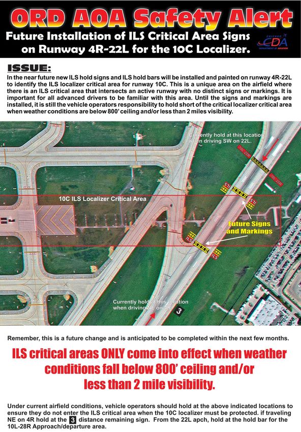
AIRFIELD LIGHTING
RUNWAY EDGE LIGHTS

- Predominantly white / last 2,000 feet amber colored -

Runway edge lights are elevated or in surface lights (where
hyspeed exit taxiways or intersecting runways prevent
elevated lights) that run the length of the runway on either
side; and have a prescribed angle of emission used to define
the edge of a runway. Runway lights are uniformly spaced at
intervals of approximately 200 feet. ORD has a bi-directional
HIRLS (High Intensity Runway Lighting System). All runways
have a 5 step light intensity system, controlled remotely by the
Air Traffic Control Tower (ATCT) & electrical vaults.

                     * NOTE * Can be used for distance remaining information

TOUCHDOWN ZONE LIGHTING
- All lights are white –
Touchdown zone lights consist of 2 rows of
transverse light bars located symmetrically
about the runway centerline. Each light bar
consists of 3 unidirectional lights facing the
landing threshold. The rows of light bars
extend to 3,000 feet from the threshold with the
first light bars located 100 feet from the
threshold.

RUNWAY CENTERLINE LIGHTING

- Centerline lights are predominantly white
except the last 3000 feet. The last 3,000
feet of the runway centerline lights are
color coded to warn pilots/ground vehicles
of the impending runway end. Alternating
red and white lights are installed, starting
with red from 3,000 feet to 1,000 feet, and
red lights are installed in the last 1,000 feet
of the runway –

The lights are located along the runway
centerline at 50 foot equally spaced intervals.

                     * NOTE * Can be used for distance remaining information

                                                     43
THRESHOLD / RUNWAY END LIGHTS
- Threshold lights emit green light outward from
the runway, and emit red light toward the runway
to mark the ends of the runway –
Fixed lights arranged symmetrically left and right of the
runway centerline. The green lights indicate the landing
threshold to arriving aircraft and the red lights indicate
the end of the runway for departing aircraft/ground
vehicles. The red and green lights are usually
combined into one fixture and special lenses or filters
are used to emit the desired light in the appropriate
direction.
TAXIWAY CENTERLINE LIGHTING SYSTEM
TAXIWAY CENTERLINE LIGHTS
- Consists of unidirectional or bidirectional in pavement steady burning
green lights installed parallel to the centerline of the taxiway -
Taxiway centerline lights provide additional taxi guidance between the runway
and apron areas.
TAXIWAY LEAD-ON/LEAD-OFF LIGHTS
- Consist of steady burning green/yellow lights -
Lead-off lights provide visual guidance to persons exiting the runway and are
color-coded to warn pilots and ground vehicles that they are within the runway
environment or instrument landing system (ILS) critical area. Alternate green
and yellow lights are installed from the runway centerline (beginning with a
green light) to one centerline light position beyond the runway hold or ILS
critical area hold position ending with a yellow light. The fixture used prior to
the runway hold or ILS critical area position must always be bidirectional:
green when approached from the taxi direction and yellow when approached
from the runway direction. For acute-angled exits, taxiway centerline lead-off
lights begin 200 feet prior to the point of curvature of the designated taxiway
path.
Lead-on lights provide visual guidance to pilots and ground vehicles entering
the runway. They are the same yellow/green color pattern as lead-off lights to
warn pilots and vehicle drivers that they are within the runway environment or
ILS critical area.
44You can also read