CLEAN GRID VISION: A U.S. PERSPECTIVE - NREL
←
→
Page content transcription
If your browser does not render page correctly, please read the page content below

Accelerating the transformation
 of power systems

CL EAN
GRID
VI SIO N:
A U.S. PERSPECTIVE
Chapter 1. Clean Grid Scenarios pdf

Chapter 2. Distribution Issues and Tools pdf

Chapter 3. Transmission Grid-Supporting Technologies

Chapter 4. Demand-Side Development pdf

Chapter 5. Global Power Market Trends pdf

 Technical Report
 NREL/TP-5C00-78644
 September 2021
 Contract No. DE-AC36-08GO28308

CLEAN GRID VISION:
 A U.S. PERSPECTIVE

 Chapter 3. Transmission Grid-Supporting Technologies

 Vahan Gevorgian, Jun Hao, Rui Yang, Yingchen Zhang, Ella Zhou —
 National Renewable Energy Laboratory

Suggested Citation:
Gevorgian, Vahan, Jun Hao, Rui Yang, Yingchen Zhang, and Ella Zhou. 2021. Clean Grid Vision: A U.S. Perspective
– Chapter 3. Transmission Grid-Supporting Technologies. Golden, CO: National Renewable Energy Laboratory.
NREL/TP-5C00-78644. https://www.nrel.gov/docs/fy21osti/78644.pdf.

National Renewable Energy Laboratory NREL is a national laboratory of the U.S. Department of Energy
15013 Denver West Parkway Office of Energy Efficiency & Renewable Energy
Golden, CO 80401 Operated by the Alliance for Sustainable Energy, LLC
303-275-3000 | www.nrel.gov
 This report is available at no cost from the National Renewable
Technical Report | NREL/TP-5C00-78644 | September 2021 Energy Laboratory (NREL) at www.nrel.gov/publications.

NREL prints on paper that contains recycled content. Contract No. DE-AC36-08GO28308
NOTICE STATEMENT:

This work was authored by the National Renewable Energy Laboratory, operat-
ed by Alliance for Sustainable Energy, LLC, for the U.S. Department of Energy
(DOE) under Contract No. DE-AC36- 08GO28308. Funding provided by the
Children’s Investment Fund Foundation under Contract No. ACT-15-00008.
The views expressed in the report do not necessarily represent the views of
the DOE or the U.S. Government or any agency thereof.

This report is available at no cost from the National Renewable Energy
Laboratory (NREL) at www.nrel.gov/publications.

U.S. Department of Energy (DOE) reports produced after 1991 and a growing
number of pre-1991 documents are available free via www.OSTI.gov.

NREL prints on paper that contains recycled content.
Acknowledgments
The Clean Grid Vision—A U.S. Perspective is a part of the 2015–2021 Chinese Programme for a Low-
Carbon Future, funded by the Children’s Investment Fund Foundation Contract No. ACT-15-00008. It is
supported by the National Renewable Energy Laboratory’s (NREL's) 2016–2021 Memorandum of
Understanding with China’s State Grid Energy Research Institute (SGERI).

During the 6-year program, the project team conducted conferences, meetings, and tours in the United
States, China, and Europe, with the support from various U.S. and international entities. These
engagements enhanced our understanding of the issues discussed in this report, and we would like to
thank the entities that made such exchanges possible:

● U.S. Department of Energy
● U.S. Department of State
● U.S. Federal Energy Regulatory Commission
● California Independent System Operator
● Electric Reliability Council of Texas
● PJM Interconnection LLC
● California Public Utilities Commission
● Public Utilities Commission of Texas
● Xcel Energy
● Electric Power Research Institute
● Regulatory Assistance Project
● International Energy Agency
● Energinet
● National Energy Administration of China
● State Grid Corporation of China
● China National Development and Reform Commission Energy Research Institute
● China National Renewable Energy Centre
● China Electric Power Research Institute
● China Electric Power Planning and Engineering Institute
● Tsinghua University
● North China Electric Power University.
Since the beginning of the program, an International Expert Group of senior-level experts has been
assembled to provide guidance, feedback, and review of the strategic direction and research content of the
program. The authors would like to acknowledge the valuable guidance and review provided by the
International Expert Group during the preparation of the report. The Clean Grid Vision does not
necessarily reflect their opinions or the opinions of their affiliated institutions. The members who have, at

 iii
times, served on the International Expert Committee between 2015–2021 and their affiliations as of 2021
are (in alphabetical order):

 Fatih Birol International Energy Agency

 Roland Brundlinger Austrian Institute of Technology

 Leon Clarke Pacific Northwest National Laboratory

 Laura Cozzi International Energy Agency

 Paolo Frankl International Energy Agency

 Dolf Gielen International Renewable Energy Agency

 Toni Glaser German Federal Ministry for Economic Affairs and Energy

 Hannele Holtinnen VTT Technical Research Centre of Finland

 Peter Jorgensen Energinet

 Daniel Kammen University of California, Berkeley

 Valerie Karplus Massachusetts Institute of Technology

 Hans Jorgen Koch Nordic Energy Research

 Jiang Lin Lawrence Berkeley National Laboratory

 Mark O'Malley Energy Systems Integration Group

 Lynn Price Lawrence Berkeley National Laboratory

 Martin Schope German Federal Ministry for Economic Affairs and Energy

 Charlie Smith Energy Systems Integration Group

 Ryan Wiser Lawrence Berkeley National Laboratory

SGERI developed the counterpart report, Clean Grid Vision—A Chinese Perspective. The collaborative
research with SGERI during the course of the program provided the authors with insights into the Chinese
power system and stimulated fresh thinking on some of the common challenges in energy transition.

In addition, this report benefited from thoughtful review by the following individuals at NREL: Douglas
J. Arent, John Barnett, Ron Benioff, Jaquelin Cochran, Bethany Frew, Jessica Lau, Trieu Mai, Caitlin
Murphy, Yinong Sun. Isabel McCan, Liz Breazeale, Chris Schwing, and Liz Craig provided editing,
design, and outreach support. Finally, Elizabeth Weber, Patricia Statwick, and Katie Contos provided
critical program support that enabled the daily operation of this multiyear cross-center international
program.

Any error or omission in the report is the sole responsibility of the authors.

 iv
List of Acronyms
AGC automatic generation control
BESS battery energy storage system
DOE U.S. Department of Energy
EES electrical energy storage
EPS electric power system
EPRI Electric Power Research Institute
ERCOT Electric Reliability Council of Texas
FACTS flexible AC transmission systems
FERC Federal Energy Regulatory Commission
FFR fast frequency response
IBR inverter-based resource
IEA International Energy Agency
ISO independent system operator
NERC North American Electric Reliability Corporation
NREL National Renewable Energy Laboratory
PV photovoltaic
VAR volt-amp reactive
VRE variable renewable energy

 v
Preface
The Clean Grid Vision—A U.S. Perspective is a part of the National Renewable Energy Laboratory’s
(NREL)’s 2015–2021 Chinese Programme for a Low-Carbon Future and collaborative research with
China’s State Grid Energy Research Institute (SGERI). This multiyear program seeks to build capacity
and assist Chinese stakeholders to articulate low carbon pathways to achieve energy systems with a high
share of renewable energy, energy efficiency, and low carbon emission.

The Clean Grid Vision comprises two major reports: Clean Grid Vision—A U.S. Perspective, written by
NREL, and Clean Grid Vision—A Chinese Perspective, written by SGERI. The former summarizes
NREL’s lessons learned on some of the main issues in power system transition:

● Power system planning and operational analysis are discussed in Chapter 1, “Clean Grid Scenarios.”
● Renewable grid integration challenges and modeling tools at the distribution network level are
 discussed in Chapter 2, “Distribution Issues and Tools.”
● Grid reliability and stability challenges and the technologies to address them at the transmission-
 network level are discussed in Chapter 3, “Grid-Supporting Technologies.”
● Recent dynamics in electricity demand such as energy efficiency, demand response, and
 electrification are discussed in Chapter 4, “Demand-Side Developments.”
● Emerging issues in power market design and market evolution related to the increasing penetration of
 renewable energy are discussed in Chapter 5, “Power Market Trends.”
The scope of Clean Grid Vision—A U.S. Perspective is limited to summarizing the main lessons learned
and best practices through NREL’s power system research in the past 6 years, with a focus on the U.S.
power system. It can be compared to and contrasted with SGERI’s report that focuses on China’s power
system.

As a summary report, most of the works cited here were conducted during 2015–2020. While some of the
assumptions for these studies, especially the ones related to renewable energy and battery technology
costs, are outdated, the main conclusions remain salient and offer valuable insights for planning and
operating power systems and power markets with high levels of renewable energy.

More information on the Clean Grid Vision is available at www.nrel.gov/international/clean-grid-
vision.html.
Suggested Citation – Chapter:
Gevorgian, Vahan, Jun Hao, Rui Yang, Yingchen Zhang, and Ella Zhou. 2021. Clean Grid Vision: A U.S.
Perspective – Chapter 3. Transmission Grid-Supporting Technologies. Golden, CO: National Renewable
Energy Laboratory. NREL/TP-5C00-78644. https://www.nrel.gov/docs/fy21osti/78644.pdf.
Suggested Citation – Entire Report:
Zhou, Ella, ed. 2021. Clean Grid Vision – A U.S. Perspective. Golden, CO: National Renewable Energy
Laboratory. www.nrel.gov/international/clean-grid-vision.html.

 vi
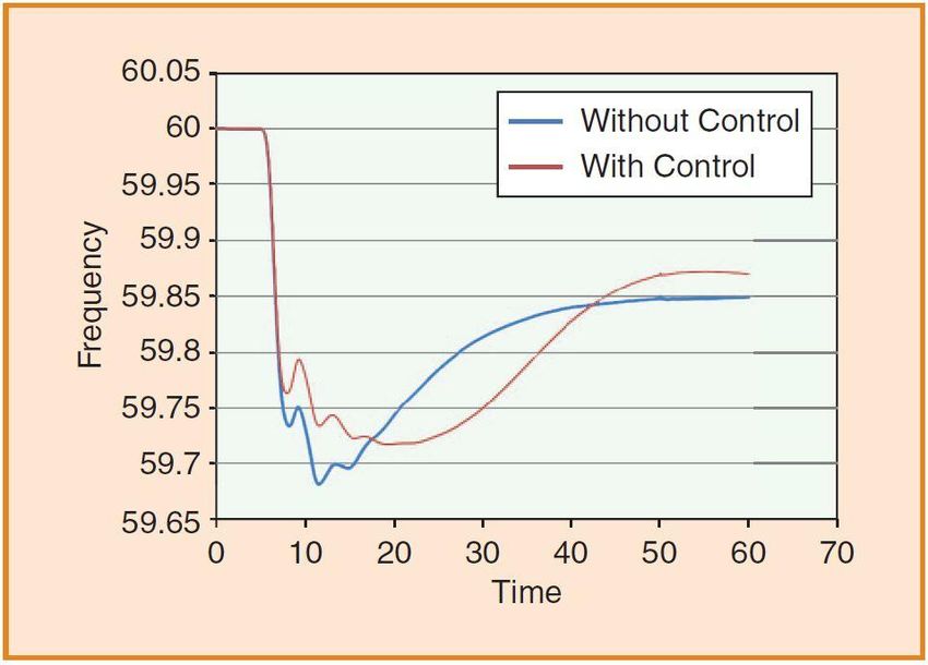
Table of Contents
Chapter 3: Transmission Grid-Supporting Technologies ....................................................................... 1
 Highlights ............................................................................................................................................... 1
 3.1 Introduction: What Is Grid Reliability?......................................................................................... 1
 3.2 Types of Reliability Services ........................................................................................................ 4
 3.3 Overview of Reliability Metrics and Standards: U.S. Perspectives ............................................ 10
 3.4 Reliability Impacts by Variable Renewable Generation ............................................................. 11
 3.5 Reliability Services by Renewable and Energy Storage ............................................................. 13
 3.5.1 Application Demands of Energy Storage for Large Power Grids With High Penetration
 Renewable Energy: Grid Frequency Control, System Flexibility .................................. 14
 3.5.2 The Method for Analyzing the Frequency Regulation Value of Energy Storage for High
 Penetration Proportion Renewable Energy Integration and Case Study ........................ 17
 3.5.3 Value Assessment Method of Energy Storage for Improving System Flexibility ......... 19
 3.6 Reliability Services by Modern Transmission Technologies ...................................................... 20
 3.7 Examples of Field Demonstration Projects ................................................................................. 23
 3.8 Grid-Forming Inverters ............................................................................................................... 24
 3.9 Conclusion................................................................................................................................... 25
References ................................................................................................................................................. 27

 vii
List of Figures
Figure 3- 1. Power systems ........................................................................................................................... 2
Figure 3- 2. Texas blackout, February 15, 2021 ........................................................................................... 3
Figure 3- 3. Generation types and capability for grid stability ..................................................................... 5
Figure 3- 4. VRE with and without synthetic inertia controls ...................................................................... 6
Figure 3- 5. PV plant participation in AGC .................................................................................................. 7
Figure 3- 6. Types of operating reserve ...................................................................................................... 12
Figure 3- 7. A plant providing primary frequency response ....................................................................... 13
Figure 3- 8. A snapshot of 2-s plant active power data............................................................................... 16
Figure 3- 9. System frequency (a) and BESS response (b) ......................................................................... 19
Figure 3- 10. Thyristor Controlled Series Capacitor schematic .................................................................. 21
Figure 3- 11. Static Synchronous Compensator schematic ......................................................................... 22
Figure 3- 12. Unified Power Flow Controller schematic ............................................................................ 23
Figure 3- 13. Grid forming: essential for stable operation .......................................................................... 25
Figure 3- 14. Grid-forming inverter ............................................................................................................ 25

List of Tables
Table 3- 1. Service Comparison.................................................................................................................... 9

 viii
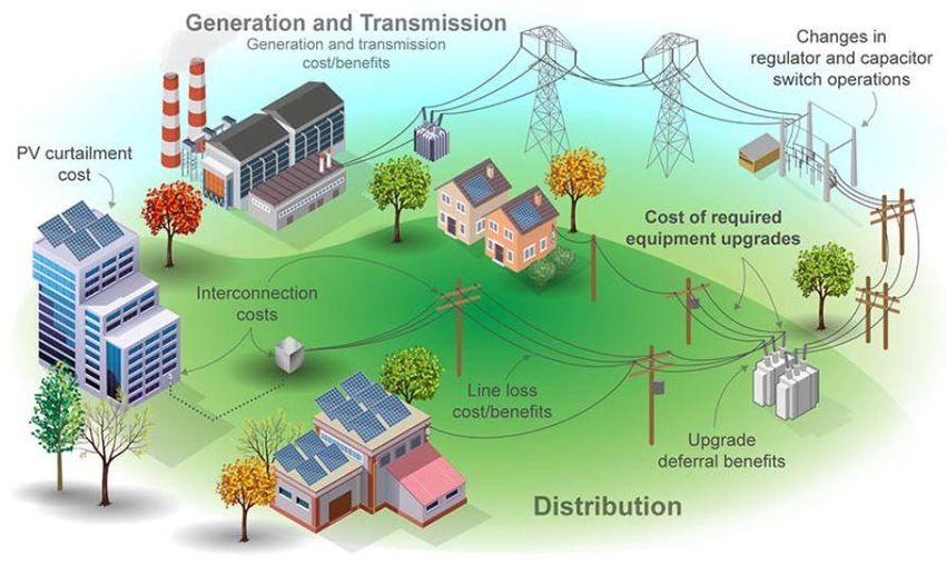
Chapter 3: Transmission Grid-Supporting
 Technologies
Highlights
● New reliability and stability challenges may emerge as the power system evolves toward inverter-
 dominated systems.
● Renewable generators and storage have been demonstrated to provide reliability services and grid
 flexibility.
● Grid-forming inverters with carefully designed control functions can provide all reliability
 requirements based on current grid codes and potentially can meet future resilient requirement (e.g.,
 black start).
● Modern grid technologies, such as flexible AC transmission systems, can further enhance grid
 reliability under high penetration of renewable energy.
3.1 Introduction: What Is Grid Reliability?
This section will discuss the reliability metrics and standards used in North America, how these standards
define the reliability requirements for planning and operation. As the power system continues to evolve,
Federal Energy Regulatory Commission (FERC) and North American Electric Reliability Corporation
(NERC) continuously improve reliability metrics and standards to keep up with a growing need for a
refined understanding of the services necessary to maintain a reliable and efficient system. NERC’s
responsibility includes development and enforcement of reliability standards, annual assessment of
seasonal and long-term reliability, and monitoring the bulk power system through system awareness, and
so on. Electricity, unlike water and gas, cannot be stored in large volumes at this time. Electricity must be
generated and used at the same time, which means the supply and demand needs to be balanced. Another
characteristic of electricity is that it cannot be routed over transmission lines. This means that the
generation and transmission operations must be monitored and controlled in real time. Therefore, grid
reliability is fundamental to secure the delivery of energy. Figure 3- 1 shows the basic components of a
power system. Electricity is generated at power plants and delivered through high-voltage transmission
lines and low-voltage distribution lines to customers. Transformers step up the voltage at power plants for
energy saving and step down the voltage substation for safe and efficient delivery of energy.

 1
Figure 3- 1. Power systems
 Source: [1]

The generation and transmission elements and their corresponding control system comprise the bulk
power system. NERC defines the reliability of the interconnected bulk power system in terms of two
basic and functional aspects [1]:

● Adequacy: The ability of the power system to provide the overall electricity and energy demand of
 the customers at all times, including scheduled usage and reasonably unscheduled demand.
● Operating Reliability: The ability of the bulk power system to undergo abrupt disturbances, such as
 electricity short circuits or unpredicted loss of system elements from contingencies, while preventing
 uncontrolled cascading blackouts or equipment damage.
All other system disturbances that cause the unpredicted or uncontrolled interruption of customer demand,
regardless of cause, fall under operating reliability. When these interruptions are contained within a
localized area, they are considered unplanned interruptions or disturbances. When they spread over a wide
area of the grid, they are referred to as “cascading blackouts”—the uncontrolled successive loss of system
elements triggered by an incident at any location. Cascading results in widespread electric service
interruption that cannot be restrained from sequentially spreading beyond an area predetermined by
studies.

Adequate actions need to be taken to keep the balance between generation and demand within a control
area. In North America, these actions include:

● Public appeals
● Interruptible demand: The demand that can be curtailed or interrupted by utility company or by end
 user at the request of the system operators.
● Voltage reduction

 2
● Rotating blackouts: Each distribution feeder is disconnected for a certain time, typically 20–30
 minutes, and then the feeder is connected back to power grid and another feeder is disconnected, and
 so on, transferring the outages among feeders.
Resiliency of the bulk power system is dependent on both adequacy and operating reliability and is the
ability of power system to reduce the risk of outages and unserved loads due to high-impact low-
probability events such as cold wave that impacted the operation of power system in Texas in February of
2021.

Penetration of very high shares of inverter-based resources (IBRs) brings new reliability challenges to the
grid in the form control interactions between IBRs, subsynchronous oscillations, harmonics resonances,
etc. To address these new reliability challenges, a new set of simulations tools is needed to understand the
nature of such instabilities and develop solutions that can be used at the system planning stage and
mitigation controls to address these issues if they occur during real-time operation of the system. This, in
turn, will raise a need in new reliability metrics, standards, and requirements adopted to the evolving grid
conditions, especially considering the fact that certain shares of grid-forming services will be provided by
IBRs.

 Figure 3- 2. Texas blackout, February 15, 2021
The blackout started at around 1:30 a.m. on February 15, 2021, after record winter load in Texas that was
increasing steadily since February 10 due to an arctic cold blast that impacted the whole state. Due to
extreme cold, several gas and coal power plants stopped operating, and generation decline continued
through most of the day. The power system operator was able to stabilize the system by disconnecting
around 20 GW of loads, causing rolling power outages. The system recovery started around midday on
February 17. This event coincided with a period of low wind and solar generation, making the impact on

 3
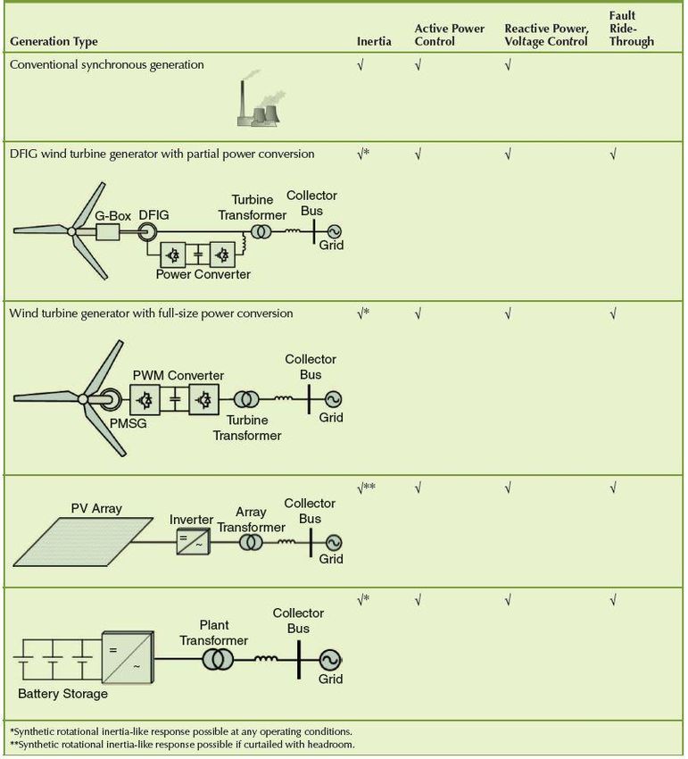
the system even more severe. This event demonstrated the importance of system resiliency that needs to
be addressed in both planning and operation of power grid.

The recent Manhattan blackout of July 2019 [18], for example, was an uncontrolled cascading blackout.
In contrast, what happened in the summer of 2000 in California [19] is a controlled rotating blackout to
keep the balance between supply and demand; however, the four actions listed above are the last defense
to prevent uncontrolled power outages/blackouts. The best strategy is to improve grid reliability and avoid
taking actions like rotating blackouts. Reliability standards are enforceable in all interconnected
jurisdictions in North America: the continental United States; the Canadian provinces of Alberta, British
Columbia, Manitoba, New Brunswick, Nova Scotia, Ontario, Quebec, and Saskatchewan; and the
Mexican state of Baja California Norte. Following adoption of a standard by the NERC Board of
Trustees, NERC files the standard with the appropriate authority in each jurisdiction. In the United States,
NERC petitions FERC for approval of standards.

3.2 Types of Reliability Services
This section will discuss the types of the existing essential reliability services as defined by NERC and
new evolving reliability services for variable generation to provide their share of grid support [2] [3]. The
services discussed will include:

● Active power control capabilities
● Fast frequency response (FFR)
● Primary frequency response
● Secondary frequency response or participation in automatic generation control (AGC)
● Ability to follow security-constrained economic dispatch set points that are sent every 5 minutes
 through its real-time economic dispatch market software.
● Voltage, reactive, and power factor control and regulation.

 4
Figure 3- 3. Generation types and capability for grid stability
 Source: [4]

AGC is a centralized mechanism of operational plans and requires the participation of elements in a
power grid for automatically adjusting generation within a balancing area. AGC plays a vital role in the
power system. It can provide regulation service and bring the frequency back to a nominal level after a
grid disturbance. Wind, photovoltaic (PV) systems, and battery storage systems can offer active and
reactive power control in a similar way to traditional synchronous generators. The development of
inverters enables the potential for the control of active and reactive power separately. Wind turbines are
able to provide extra active power into the power system through utilizing the energy stored in the

 5
rotating mass of blades and generators. PV inverters can also achieve the same support if curtailment is
reserved. Energy storage can be managed to adjust its active power to imitate the inertial response of
rotating machines like synchronous machines. As the penetration of variable renewable energy (VRE)
increases in the power systems, the grid requires greater flexibility to deal with the changes in generation
aspect. VRE can only generate power when its resources are available. PV systems, in particular, are
limited by the diurnal cycle. It means there is no power output from PV systems during night and will
lead to larger load ramps than other kinds of power sources because PV generators are correlated well in
the same geographical area. Wind power can also cause ramps, but these ramps usually happen during a
couple of hours. Active power control can help to limit or mitigate the ramping rate by limiting the
injections from PV systems, or managing shiftable load to match the generation cycle of VRE. During the
time window when both wind and solar have high output, active power control will curtail part of the
generation, which is proven to be the most economic strategy. The decision is based on multiple
variables.

The inertial response is the instant response to a power system contingency, and it overcomes the
immediate imbalance between power supply and power demand. It is an important factor to determine the
transient stability and small signal stability. Synchronous machines can provide the inertial response by
nature. Active power controllers for VRE can realize a synthetic inertia response through a specific
designed strategy.

 Figure 3- 4. VRE with and without synthetic inertia controls
 Source: [3]

 6
A wind turbine can realize inertial control by utilization of its kinetic energy stored in the rotating mass of
wind blades. Thus, the wind turbines can mimic inertial response from traditional synchronous generators.
The response is achieved by improving the power output of wind turbines in a short period. The short
power injection can help the grid to reduce the rate of change of frequency during a
contingency/imbalance event. Figure 3- 4 shows the results of our research [3]. The presence of inverters
enables PV systems to provide FFR when the PV systems have headroom to provide active power during
an underfrequency event. Another way for PV to provide inertia response is combining with energy
storage systems.

Wind turbine and solar systems can provide droop-like response. Wind turbines can achieve this by
utilizing synthetic inertia, and solar systems need to be curtailed to achieve the primary frequency
response. Note that the plant droop is calculated in the same way as traditional generators. Our research
results also support that VRE can provide primary frequency response [5] [6].

VRE has the capability of offering secondary frequency response if the controller is designed carefully
and controlled accurately. The barrier is that precise generation forecasting is required at various time
windows to ensure the availability of reserves from wind turbines and PV panels. The VRE can also
participate in AGC. Figure 3- 5 shows the results. It should be noted that 10% of the output was curtailed
and the PV plant followed the operator’s AGC commands.

 Figure 3- 5. PV plant participation in AGC
 Source: [3]

Maintaining high-quality voltages at all feeders in a power grid is fundamental to ensuring the power is
delivered safely across the transmission network. In terms of voltage regulation and reactive power
regulation, the excitation system in conventional generators ensure output voltage is stable. VRE can
provide voltage regulation through voltage controllers. The trade-off is impairing their capability to
provide real power because it can be realized at the same time. Volt/volt-amp reactive (VAR) control and

 7
the optimization of VRE will provide necessary voltage support and minimize the impact on the ability of
renewable generators to produce real power.

Inverter-based generators have good fault ride-through capability. With the appropriate converter design,
wind energy, PV systems, and energy storage can ride through different types of balanced and imbalanced
and overvoltage and undervoltage faults and frequency fluctuation; therefore, the power system reliability
is improved. If needed, VRE can provide certain amount of reactive power to help voltage recovery.

 8
Table 3- 1. Service Comparison

 Services
Generatio Inertia FF Primary AG Voltage Oscillation Fault Short
 n Type R Frequenc C Suppor s Ride- Circuit
 y t Damping Throug Curren
 Response h t
 Synchronous
 Generators
 Real No Yes Yes Yes Yes Yes Yes

 Synchronous
 Condensers
 Real No No No Yes Yes Yes Yes

 Wind Real Depends
 combine on
 d with Yes Yes Yes Yes Yes Yes electric
 controls topology

 Solar PV

 Synthetic Yes Yes Yes Yes Yes Yes No

 Solar CSP

 Real No Yes Yes Yes Yes Yes Yes

 Batteries

 Synthetic Yes Yes Yes Yes Yes Yes No

 Flywheels
 Real
 combine Yes Yes Yes Yes Yes Yes No
 d with
 controls
Supercapacitors

 Synthetic Yes Yes Yes Yes Yes Yes No

 H2 Fuel Cells

 Synthetic Yes Yes Yes Yes Yes Yes No

 HVDC
 No No No No Yes Yes Yes No

 9
In short, Table 3- 1 shows comparative characteristics of conventional synchronous generator-based
resources and IBRs, including wind and solar generation and some representative inverter-coupled
storage technologies. Essential reliability services such as inertial response, primary frequency response,
ability to participate in AGC, voltage regulation, fault ride-through performance, and other services, such
as FFR and wide area stability services, for damping of various types of power system oscillations. The
ability of the resource to provide short circuit current contribution is compared as well. It can be observed
in Table 3- 1 that IBRs can provide all types of reliability services similar to conventional generation;
moreover, in some cases they can do it with faster response speeds and better precision, compared to
conventional technologies. This also includes ability to provide inertial response because controllability
of IBRs allows emulating different types of inertia-like response that can be optimized for system needs.
The only characteristic that differs is the inability of IBRs to contribute enough levels of current during
faults for protection activation. This issue will be discussed later in this section. High-voltage DC
transmission is considered as an important component of future IBF-based grid. High-voltage DC
transmission brings many benefits of economic long-distance overhead, underground and submarine
power transmission. Being a transmission technology, it is not able to provide many active power-based
services by itself (unless coupled with energy storage) but can be used for voltage support and stability
services. In addition, multiterminal high-voltage DC systems can be used for controlling active power
flows between terminals.

3.3 Overview of Reliability Metrics and Standards: U.S. Perspectives
This section will compare the reliability issues and concerns, metrics, and standards from the United
States and China perspectives. Despite major difference in economic aspects of power systems operation
in both countries, the main reliability concerns remain the same and can be addressed by similar risk-
mitigating technical solutions; however, the underlying market mechanisms will define the optimum
reliability improvement solutions applicable to specifics of each country.

Section 215 of the Federal Power Act requires the Electric Reliability Organization [20] to develop
mandatory and enforceable reliability standards, which are subject to Commission review and approval.
Commission-approved reliability standards become mandatory and enforceable in the United States on a
date established in the Orders approving the standards. Under the resource and demand balancing
category, BAL-001-2 [7] regulates the real power balancing control performance, which controls
interconnection frequency within defined limits. BAL-002-WECC-2a [8] regulates the quantity and types
of contingency reserve needed to guarantee reliability under various conditions. Other standards also set
requirements about common criteria, data acquisition, and frequency responses about time error
corrections and primary inadvertent. Each standard also defines the related entities and prerequisites.

For voltage and reactive standards, two aspects are regulated: (1) to protect equipment and ensure reliable
operation of the interconnection, guarantee generators provide reactive support and voltage control within
capabilities; and (2) establish performance criteria for the Western Interconnection to ensure a
coordinated manner under various normal and abnormal conditions.

FERC has been developing regulatory mechanisms for power systems, enabling VRE in capacity, energy,
and power system support markets. Back in 2011, Order No. 755 [21] aimed to improve the rewards for
fast-responding energy like flywheels. Later in 2013, FERC enacted Order No. 784 [22], which guides the
independent system operators (ISOs) to services by fast-responding energy. FERC proposed reactive
power requirements for Non-Synchronous Generation in Order 827 [23]. In Order No. 819 [24], FERC
revised regulations to bring up competitions in the sale of primary frequency response services. FERC is
concentrating on other frequency services and response problems in Order No. 842 [31]. FERC Order
661-A [25] can be applied to wind energy and PV systems in some cases.

 10
3.4 Reliability Impacts by Variable Renewable Generation
Integrating large quantities of variable energy resources into North American bulk power system requires
significant changes to electricity system planning and operations to ensure continued reliability of the
grid. The section focuses on considerations that all system planners and operators must address to reliably
integrate significant quantities of variable energy resources into the bulk power system, including: inertia,
frequency response, regulation, load-following, active power control, reactive power and voltage control,
disturbance ride-through tolerance, steady-state and dynamic stability modeling, and load and generation
forecasting.

The increasing integration of renewable energy is displacing conventional power plants, which brings
major challenges to maintaining the stability of power systems all over the world. For instance, 72 GW of
conventional generation retired in the last 10 years in North America, and more than 120 GW of variable
generation has been integrated into the power grid. The integration of VRE is introducing more and more
inverter-based energy, which is making significant challenges to frequency regulation. The challenges
come from two aspects: (1) the control and generation of VRE is not sensitive to load-generation
balancing; and (2) the synchronous spinning inertia with respect to the overall generation is reduced
drastically within a balancing area. Based on the basic principle of conventional turbines, the turbine and
the rotating parts inside each power plant can store tremendous kinetic energy. Because of this, the extra
energy can be absorbed into or extracted from the synchronous generators to counteract the system
fluctuation. Thus, the frequency deviation can indicate the imbalance condition and the total amount of
rotating mass (inertia) directly reflect the ability of the interconnected system to handle fluctuations. On
the contrary, a low level of inertia means the system is vulnerable to deviations.

Solar, wind, and energy storage are totally different from conventional power plants. The generation
produced by VRE sources cannot be connected to the current AC power grid directly. The power output
from VRE is DC and needs to be converted to AC before connecting to power grids. The inverter [9] is a
power electronics device, which is the interface between VRE and the AC power grid. Inverters convert
DC power to AC power and control the flow of electricity by managing semiconductor devices. Based on
the definition of an inverter, we can tell that an inverter does not comprise any rotating mass and therefore
there is no inertia in an inverter. Basically, there are two types of inverters: the grid-following inverter,
which control the output by tracking the voltage angle, and the next-generation grid-forming inverter,
which can actively control their frequency output. It is questionable that an inverter-based power system
can merely relay on grid-following control to achieve system stability. To address this issue, a next-
generation grid-forming inverter [10] is necessary. Researchers and engineers have developed
methodologies of mimicking various physical characteristics with inverters to achieve virtual
synchronous machines or virtual inertia; therefore, the inertial responses are realized through carefully
programmed controllers on inverters.

 11
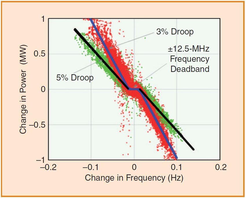
Figure 3- 6. Types of operating reserve
 Source: [3]

The power system is a dynamic system, which means the load, generation, and transmission availabilities
are balanced at real time. All three factors are variable and hard to predict. Additional capacity is reserved
to keep the frequency stability during an imbalance event; however, the variable characteristics of VRE
make it hard to determine the operating reserve and increase the importance of the operating reserve at the
same time. Another shortcoming of the VRE is the inertia reduction [11], which will also further cause
other power system stability issues. For example, the first step is to arrest the frequency changing rate
during a frequency deviation event and further stabilize the frequency at the primary frequency response
stage. Later, the grid frequency will be brought back to its prefault level so the area’s control error equals
zero at the secondary frequency response stage. Wind, solar, and energy storage can offer any kind of
operating reserves to participate in different stages of frequency response [3]. The challenge here is that
accurate generation forecast at various time horizons is required to secure the availability of the
corresponding reserves. Energy storage can be implemented as backup generation and help balance the
imbalance in case of error of prediction.

From regulation perspectives, the frequency should be maintained at a nominal level at any time. Major
frequency deviations can cause load shedding, equipment damage, and even blackouts. Concerns are
rising with the retirement of conventional generators and increasing VRE integration because the
reduction of system inertia can impair the system’s ability to absorb the deviation. VRE energies can offer
primary, secondary, and tertiary response if they are controlled correctly. The advantage VRE has over
conventional generators is the response speed [62]. Wind turbines can provide frequency responses easier
than other VRE due to the rotating mass, such as wind blades. For primary frequency response, wind
turbines have the capability to provide droop-like response and improve the frequency nadir and the
steady-state frequency. In Orders 755 and 784, FERC required improving the mechanisms by which
frequency regulation services are procured and enabling compensation by fast-response resources, such as
energy storage. In addition, FERC recently issued a notice of proposed rulemaking to enable the
aggregation of distributed storage and distributed generation [26]. The combination of PV system and
energy storage can offer stable frequency response. Even the PV system solely can provide ancillary
services if its output is curtailed. Figure 3- 7 shows a PV plant providing primary frequency response (3%
and 5% droop).

 12
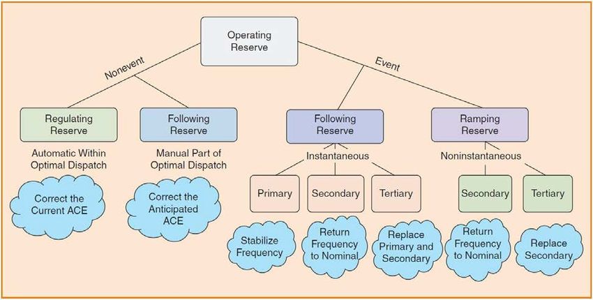
Figure 3- 7. A plant providing primary frequency response
 Source: [3]

Another aspect that all system planners and operators must pay attention to is steady-state and dynamic
stability modeling. Due to the variability of VRE and the evolution of power systems, FERC stated that
there is an urgent need for a refined understanding of the system services to maintain the system’s
reliability and efficiency [27]. The current system simulation and modeling are only taking tests at several
crucial time points. If test results are good at these crucial points, the system can be stable; however, the
increasing VRE causes increasing system variability. Thus, dynamic stability modeling is needed to
ensure the power system is balanced and stable at all times, particularly when the output of solar PV and
wind is ramping up or down; therefore, the dynamic modeling is very important to the power system
stability research. One important part of dynamic modeling is accurate load and generation forecasting,
especially the generation forecasting. To obtain better PV generation forecasting, more variables should
be included, such as location, angle, and weather information. If carefully designed and fully developed,
the ride-through capability of VRE is high, and VRE can even inject reactive power to the power grid to
help voltage recovery. In short, with appropriate converter design, solar PV, wind, and electrical storage
can ride through different kinds of unbalanced load, voltage fluctuation, and frequency deviation, thus
enhancing the reliability of a power grid.

3.5 Reliability Services by Renewable and Energy Storage
Electrical energy storage (EES) systems are going to help researchers and electrical engineers solve the
challenges with the increasing integration of VRE and improving the power reliability by increasing the
response speed and operating capacity. The application of EES systems is growing fast, and various sets

 13
of applications have been developed and implemented, such as frequency regulation, voltage support,
energy management, grid stabilization, and load shifting. Currently, the major EES all over the world is
pumped-storage hydropower, which is playing an important role in providing ancillary services. But the
growth of pumped-storage hydropower is slow, and battery energy storage systems (BESS) dominate the
investment in terms of installation capacity and monetary values.

Over the last decade, the development and implementation of EES has proven its potential to provide
ancillary services for the electrical power system, and, in turn, to facilitate the integration of VRE. EES
can offer tremendous support for the integration of VRE to mitigate variability and uncertainty [12]. The
large-scale implementation of energy storage can effectively reduce the wind and PV output limitation
caused by various factors such as line congestion and overgeneration. The U.S. government continuously
focuses on the development of EES technologies, and the U.S. Department of Energy (DOE) also set the
long-term goals for EES as the following:

● Compared with other technologies, EES should be cost-competitive.
● The related regulatory environment is crucial to utilizing the potential of EES.
● Proper compensation for EES should be proposed for long-term benefits.
● Seamless EES integration is essential for vast implementation.
FERC has focused on the regulations related to EES for a while, thus facilitating the implementation of
EES technologies in different kinds of markets such as energy, capacity, and ancillary services. In 2011,
Order No. 755 was issued by FERC to raise the payments for fast-responding resources. Later in 2013,
FERC issued Order No. 784, which guides ISOs to reward services provided by fast-responding
resources, including EES. Order No. 819 was issued by FERC to facilitate the competition of primary
frequency response services.

3.5.1 Application Demands of Energy Storage for Large Power Grids With High
Penetration Renewable Energy: Grid Frequency Control, System Flexibility
This section will discuss the role of electric system flexibility options in the large-scale deployment of
renewable energy using enabling technologies such as energy storage. Key factors in improving grid
flexibility include: (1) increasing the ramp range and rate of all generation sources to follow the variation
in net load; and (2) the ability to better match the supply of renewable resources with demand via
increased spatial diversity, shiftable loads, or energy storage. Overall system flexibility largely depends
on the mix of generation technologies in the system (For example, a system dominated by gas or hydro
units will likely have a higher level of flexibility than a system dominated by coal or nuclear generators.)
Even with a completely flexible system, achieving very high levels of variable generation requires
enabling technologies such as energy storage to address the fundamental mismatch of supply and demand.

Utility-scale EES systems provide various services as follows:

● Power system ancillary services
● Store and shift electric energy
● Manage peak load
● VRE ramping support and load following
● Increasing renewable energy usage
● Frequency regulation (inertia response, FFR, and primary frequency response)
● Spinning and nonspinning reserves

 14
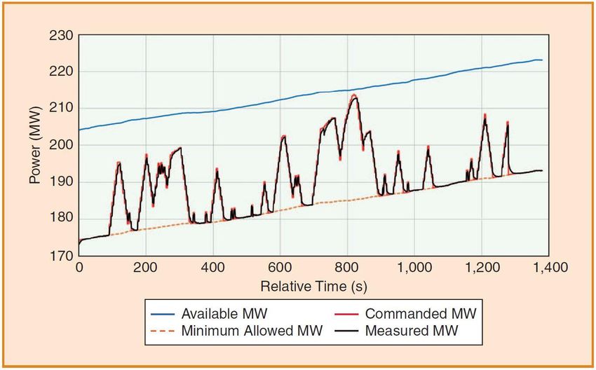
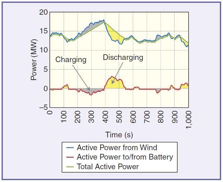
● Increase supply capacity
● Supplemental reserves
● Reactive power and voltage support
● Ability of black start
● Load support during contingencies
● EES equipped with inverter can increase grid stability.
● Power plant implementation
● Stacked services.
In the United States, the amount of installed battery energy storage was about 658 MW as of 2017. 63%
of the installation aimed to help with frequency regulation, 20% was about spinning reserves [28]. Among
all ancillary services, frequency regulation is probably one of the most critical services. In the United
States, EES is conceived to have the potential to be the first choice for frequency regulation in the future
power system. The plan for EES to provide peak/valley load following was also proposed in the United
States for some island systems. Figure 3- 8 shows an example of BESS coupled with wind farms in
Hawaii. This particular BESS was controlled to provide ramp-limiting service to the wind power plants in
the small island system.

 15
Figure 3- 8. A snapshot of 2-s plant active power data
 Source: [29]

Figure 3- 8 shows a wind-battery storage system at Kahuku Wind Farm in Hawaii. In this project, the
flow of the battery’s active power are based on the trends of active power of the wind power plant [29].
The project showed that the BESS can help to significantly reduce the frequency of large ramping events.
EES, especially BESS, can significantly mitigate the variability and intermittency of VRE and improve
the value and viability of VRE.

One of the main purposes of building BESS is to help increase grid flexibility, including reducing
aggregate system-level ramps caused by VRE. VRE energies can merely produce electricity when its
resources are available, such as solar PV and wind energy; however, the output of VRE (such as solar PV)
systems is very similar within a certain geographical area, which means their generation curves are the
same. This will increase/decrease the ramp rate in a short time drastically, reduce the system stability, and
increase the burden of conventional generators. Ramps should be limited to decrease the adverse impact
on power system stability and enable more VRE to be integrated into the grid. Minimizing ramps can
optimize the cost of ancillary services of traditional power plants. BESS can be charged during ramp-up
time and discharged during ramp-down time without curtailment of generation and requirement of reserve
services from other energy sources. For example, if a utility-scale PV plant is equipped with BESS, the
battery system can be charged during the morning and at noon when PV outputs are ramping up or at
maximum and can be discharged before sunset to compensate the ramp-down caused by PV output
decreasing.

 16
In general, the BESS controller can be designed to provide various forms of active and reactive power
control. BESS can have capability to provide inertial response, FFR, and primary frequency response. In
addition, the BESS can provide reactive power control in the form of kVAR-voltage droop during
dynamic and fault conditions.

All BESS active power control components can be combined in a single simplified equation, so at any
instant in time, the total BESS power (injecting or absorbing) is:

 ( ) = ( ) + ∆ ( ) + ∆ ( ) + ∆ ( ) + +∆ ( ) + ∆ ( ) (1)

where ( ) is the BESS dispatch set point; ∆ ( ) is the portion of the commanded power set point for
the BESS state of charge (SOC) control; ∆ ( ) is the BESS inertial response (or response proportional to
the rate of change of frequency); ∆ ( ) is BESS FFR response; ∆ ( ) is the BESS droop
response; and ∆ ( ) is the BESS AGC response.

Depending on the type of service that the BESS is providing, the individual components in (1) can be
activated at the proper times. For example, ∆ ( ) will start first at the beginning of the event, as soon as
a large rate of change of frequency is detected; then either ∆ ( ) or ∆ ( ) will kick in (the BESS
can provide either FFR or droop response, but it cannot do both at the same time). The ∆ ( )
component will follow the AGC set points from the system operator for secondary frequency control and
frequency regulation. Equation (1) can be expanded to show components of interest in more detail:

 ( ) − ( )
 ( ) = ( ) + ∆ ( ) − 2 − + ∆ ( ) (2)

where - is the scheduled grid frequency, ( ) is the grid frequency at any point, and H is emulated
inertia constant.

It is clear that high penetration of variable generation increases the need for all flexibility options,
including storage, and it also creates market opportunities for these technologies [32].

3.5.2 The Method for Analyzing the Frequency Regulation Value of Energy
Storage for High Penetration Proportion Renewable Energy Integration and Case
Study
Electric power system (EPS) operators use a variety of scheduling techniques to match electricity
generation and demand. When the total supply of energy is different from the total demand, system
operators must deploy operating reserves (including regulating, following, contingency, and ramping
reserves) to correct the energy imbalance. The way they do this, and especially the way they plan for this,
can affect the reliability and efficiency of the power system—particularly if it includes large amounts of
variable generation. In this section, we will discuss the tools used to evaluate economic and reliability
metrics when employing different operating reserve strategies, including use of energy storage
technologies. Such multiple-timescale, interconnected simulation tools that include security-constrained
unit commitment, security-constrained economic dispatch, and AGC submodels enable FESTIV to fully
investigate the trade-offs in economic benefits, reliability benefits, and incentive structures.

There are requirements, or minimum technical requirements that utility-scale VRE shall carry out, such as
solar PV, wind, and EES. Renewable generation also plays a vital role in frequency regulation of existing

 17
and future power grids. With the increasing penetration of EES, particularly BESS, utility-scale BESS
should participate in reliability controls, including:

● Low-voltage ride-through and high-voltage ride-through
● Voltage regulation
● Steady-state and dynamic reactive power controls
● Frequency fault ride-through
● Frequency response and frequency regulation
● Ramp-rate regulation
● Active power control.
According to our research, NREL’s suggestions include requirements on ranges for inertial control
deadbands for frequency and high rate of change of frequency and the magnitude of inertia response as a
percentage of prefault power level or total plant capacity [12]. For instance, the inertia response can be set
between 0.025 − 0.3 Hz for programmable frequency headland. The programmable rate of change of
frequency deadland can be within 0.1 − 2 Hz/s. The programmable magnitude of inertial response can be
in 0 − 0.15 p.u. FFR is a relative novel way to utilize BESS to deal with sudden generation or load losses
[13]. With proper knowledge of loss magnitude, BESS can be controlled to change its power output.
Thus, FFR can be a useful frequency response method for system operators. The key is to improve the
ability of the control system to resolve the loss magnitude and send the set point to control BESS. The
BESS response speed will rely on the power system stability impacts: BESS has the capability to deploy
all available reserves rapidly, which can probably result in system oscillations. FFR provided by BESS
can be based on frequency threshold, such as rate of change of frequency; however, it will need the
information of precise FFR magnitudes. NREL recorded about 20 − 30 ms constant response time by a
commercial 1 − MW/1 − MWh Lithium-ion BESS equipped with in inverter, which means that BESS
can be a productive provider of FFR service.

NREL researched the topic of what frequency response services by BESS are most effective in terms of
boosting power system performance during and after significant contingencies [12]. We built a power
system model that comprises synchronous generators with steam, gas, and hydro governors; static loads,
inertia-less wind and solar generation, and a BESS. The share of wind and solar generation took up 20%,
and the BESS took up 3.5%. We conducted a significant contingency by tripping off a generator that
powers 3% of the load. The average inertia constant for all conventional generator = 5 s. We assumed
both wind and solar generation merely supply bulk power without reliability services. The BESS ran at
zero power, so it could run at full power in either charge or discharge condition. At = 50 s, a generator
was disconnected, resulting in reduction of the frequency of the system. The base case is only traditional
generators have the ability to provide inertia and droop response, making a frequency nadir at about 59.6
Hz. The results of the experiments for this hypothetical case are shown in Figure 3- 9.

The following cases show the impacts of BESS on system frequency:

● Case 1: BESS offering inertial response (200-ms delay)
● Case 2: BESS supplying droop response (200-ms delay)
● Case 3: BESS supplying inertial response and droop (200-ms delay)
● Case 4: BESS supplying FFR (2-s delay)

 18
● Case 5: BESS offering inertia (200-ms delay) and FFR (2-s delay).

 Figure 3- 9. System frequency (a) and BESS response (b)
 Source: [12]

3.5.3 Value Assessment Method of Energy Storage for Improving System
Flexibility
The section will discuss various methods used for examining the potential for replacing conventional
peaking capacity and flexibility resource with energy storage, including analysis of the changing technical
potential with increased storage deployment and the effect of PV and wind deployment. Details on

 19
dispatch models to evaluate renewable generation as a function of system flexibility and enabling
technologies like energy storage will be described.

Based on our past research and experiments, NREL proposed recommendations for the determination of
minimum technical requirements [14]; such regulation and assessment should at least cover some of the
following items:

● All aspects about active and reactive power services by BESS
● Black-start and grid-forming ability
● Transient fault ride-through capabilities
● Power quality regulation
● Protection regulation
● Validation of energy storage models
● Operation and control regulation
● Control and communication update.
The implementation of BESS is to mitigate the instability with the increasing integration of VRE, such as
wind and solar PV systems. Meanwhile, BESS can also lower the cost of reserves provided by
conventional power plants and decrease the headroom curtailed by VRE. Both utility companies and
regulators want the BESS to be cost-effective; therefore, the value of BESS is determined by the services
it can provide. To fully utilize the BESS, NREL proposed a list of required services by BESS and related
parameters that need to be clarified for assessment [12], including:

● Inertial response capability with programmable inertia constant H
● FFR capability with response time and maximum possible
● Frequency droop control capability with programmable droop setting and deadbands
● Ability to follow 2-s active power set-point commands from AGC systems
● Voltage droop control capability with programmable droop setting and deadbands
● Steady-state and dynamic reactive power injection or absorption capability
● Short-circuit current control capability (i.e., positive-sequence, negative-sequence, and zero-sequence
 components) under balanced and unbalanced fault conditions
● Voltage and frequency fault ride-through capability
● Grid-forming capability
● The concept of a virtual synchronous machine is rising in the industry as a flexible option to allow
 operation under a wide range of system conditions, including seamless transition between grid-
 connected and stand-alone operation.
● Control of short-circuit current in grid-forming mode under various fault scenarios.
3.6 Reliability Services by Modern Transmission Technologies
Flexible AC transmission systems (FACTS) are used to increase power transfer capability, stability, and
controllability of the networks through series and/or shunt compensation. These devices are also
employed for congestion management and loss optimization. FACTS technology is an energy conversion,

 20
transmission, and control technology that uses high-power semiconductor switching devices. Facing EPS,
it integrates manufacturing technology, modern control technology, and the traditional power grid
technology, and has become the core of FACTS. This section will provide an overview of modern
FACTS devices and their uses for reliability services in transmission grids.

A FACTS is a system consisting of static equipment used for AC transmission of electrical energy. A
FACTS aims to improve controllability and enhance transfer capability of the electrical grid [15]. A
power system dominated by FACTS devices is an electronics-based system. Incentivized by the goals of
greenhouse emission reduction and increasing electric demand, the integration of renewable energies is
increasing in recent years. In turn, the increasing VRE generation also creates novel challenges in power
grids, such as dispatch of active and reactive power, voltage and frequency stability, sub synchronous
resonance, and power quality. Thus, the VRE has the potential to compromise the stability and safety of
the power systems. Recent research shows that FACTS devices are good at solving these kinds of
problems. The key to FACTS is to incorporate power electronic devices at the transmission level to make
the system electronically controllable. The controllers inside FACTS enable FACTS to control one or
more parameters to alter the operation of transmission and enhance the power system stability and power
quality. The incorporation of FACTS can increase the ability to control dynamic power flow and decrease
the power oscillations. Besides that, FACTS devices are also capable of increasing availability of power
transfer and capacity of existing transmission lines and voltage support.

The Thyristor Controlled Series Capacitor is one of the FACTS devices. The Thyristor Controlled Series
Capacitor enables fast and continuous change of transmission-line impedance. Therefore, the active
power flowing in the transmission line should be maintained at a predefined value under various system
conditions. The figure below shows a configuration of a Thyristor Controlled Series Capacitor, which
contains a series capacitor bank in parallel with a reactor controlled by thyristor.

 Figure 3- 10. Thyristor Controlled Series Capacitor schematic
 Source: [12]

The Static Synchronous Compensator is another FACTS device, which can provide voltage support
without large banks of capacitors and reactors to supply or absorb reactive power. Static Synchronous
Compensators can be used as a controlled current source, which supply or absorb reactive power. Figure
3- 11 shows the scheme of a Static Synchronous Compensator.

 21
You can also read