Comparing feedback techniques for underwater navigation
←
→
Page content transcription
If your browser does not render page correctly, please read the page content below
Comparing
     feedback
techniques for
   underwater
    navigation

                 Master’s Thesis
                 submitted to the
                 Media Computing Group
                 Prof.Dr.Jan Borchers
                 Computer Science Department
                 RWTH Aachen University

                               by
                       Christian Schmidt

                                           Thesis advisor:
                                     Prof.Dr.Jan Borchers

                                       Second examiner:
                              Dr.-Ing. Ulrik Schroeder

                    Registration date:     11.09.2018
                     Submission date:      26.09.2018
Eidesstattliche Versicherung

___________________________                                               ___________________________

Name, Vorname                                                             Matrikelnummer

Ich versichere hiermit an Eides Statt, dass ich die vorliegende Arbeit/Bachelorarbeit/
Masterarbeit* mit dem Titel

__________________________________________________________________________
__________________________________________________________________________
__________________________________________________________________________

selbständig und ohne unzulässige fremde Hilfe erbracht habe. Ich habe keine anderen als
die angegebenen Quellen und Hilfsmittel benutzt. Für den Fall, dass die Arbeit zusätzlich auf
einem Datenträger eingereicht wird, erkläre ich, dass die schriftliche und die elektronische
Form vollständig übereinstimmen. Die Arbeit hat in gleicher oder ähnlicher Form noch keiner
Prüfungsbehörde vorgelegen.

___________________________                                               ___________________________

Ort, Datum                                                                Unterschrift

                                                                          *Nichtzutreffendes bitte streichen

Belehrung:

§ 156 StGB: Falsche Versicherung an Eides Statt
Wer vor einer zur Abnahme einer Versicherung an Eides Statt zuständigen Behörde eine solche Versicherung
falsch abgibt oder unter Berufung auf eine solche Versicherung falsch aussagt, wird mit Freiheitsstrafe bis zu drei
Jahren oder mit Geldstrafe bestraft.

§ 161 StGB: Fahrlässiger Falscheid; fahrlässige falsche Versicherung an Eides Statt
(1) Wenn eine der in den §§ 154 bis 156 bezeichneten Handlungen aus Fahrlässigkeit begangen worden ist, so
tritt Freiheitsstrafe bis zu einem Jahr oder Geldstrafe ein.
(2) Straflosigkeit tritt ein, wenn der Täter die falsche Angabe rechtzeitig berichtigt. Die Vorschriften des § 158
Abs. 2 und 3 gelten entsprechend.

Die vorstehende Belehrung habe ich zur Kenntnis genommen:

___________________________                                               ___________________________

Ort, Datum                                                                Unterschrift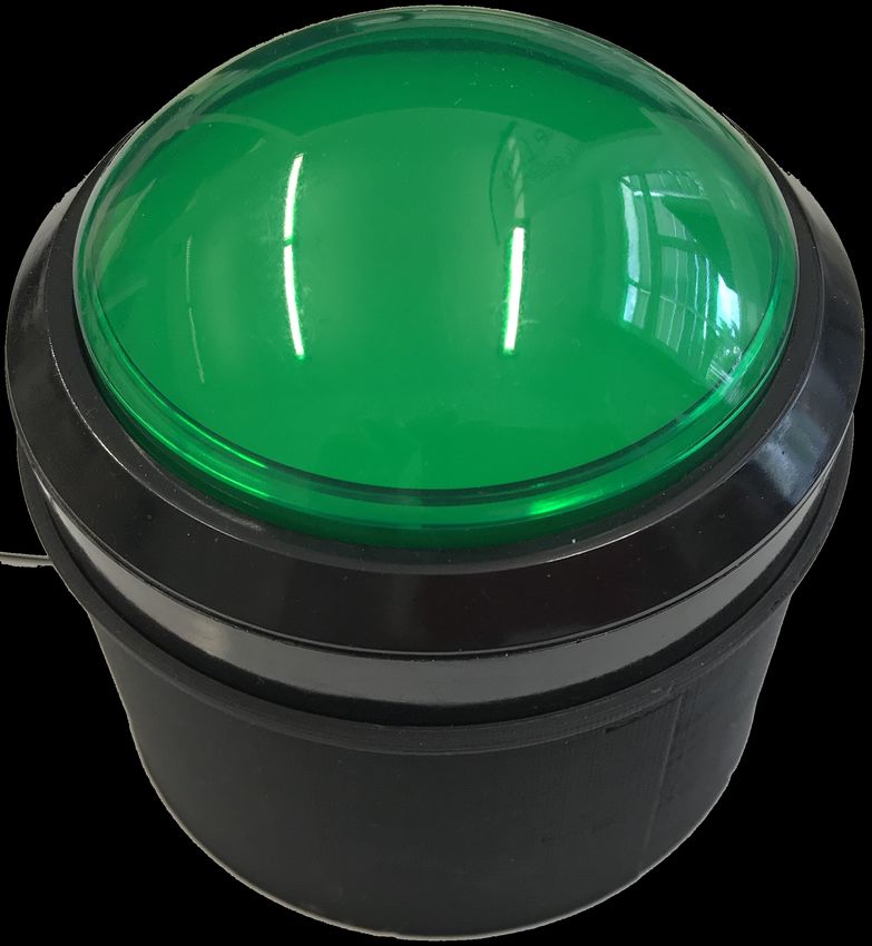
v

Contents

    Abstract                                                       xi

    Überblick                                                   xiii

    Acknowledgements                                              xv

    Conventions                                                  xvii

1   Introduction                                                   1

2   Related work                                                   5

    2.1   Underwater Navigation Systems . . . . . . .              6

    2.2   Feedback modalities . . . . . . . . . . . . . .          7

3   Hardware Prototype and Software                                9

    3.1   System Design . . . . . . . . . . . . . . . . . .        9

          3.1.1   Hardware Prototype . . . . . . . . . .          12

          3.1.2   Safety . . . . . . . . . . . . . . . . . . .    17

    3.2   Software . . . . . . . . . . . . . . . . . . . . .      17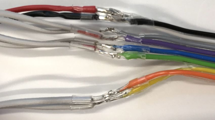
vi                                                           Contents

               3.2.1   Testing . . . . . . . . . . . . . . . . . .   20

     4   Evaluation                                                  23

         4.1   User Study . . . . . . . . . . . . . . . . . . . .    23

               4.1.1   Procedure . . . . . . . . . . . . . . . .     24

               4.1.2   Design . . . . . . . . . . . . . . . . . .    25

               4.1.3   Results . . . . . . . . . . . . . . . . . .   25

               4.1.4   Discussion . . . . . . . . . . . . . . . .    27

               4.1.5   Testing outside the water . . . . . . .       28

     5   Summary and future work                                     31

         5.1   Summary and contributions . . . . . . . . . .         31

         5.2   Future work . . . . . . . . . . . . . . . . . . .     32

     A TITLE OF THE FIRST APPENDIX                                   35

     B TITLE OF THE SECOND APPENDIX                                  37

         Bibliography                                                39

         Index                                                       43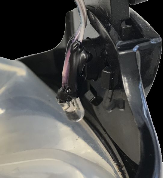
vii
List of Figures
2.1 Scubus S smart diving goggles by Noah Smith. 7
3.1 LED insulated and attached between the sil-
icone and frame of the diving goggles using
hotglue. . . . . . . . . . . . . . . . . . . . . . 12
3.2 Stretchable headband with hook and loop
fastener sewn to it. Allows comfortable ad-
justment on different head froms and sizes. . 13
3.3 theromelectric cooler mounted to the head-
band to be placed directly on the users skin. . 14
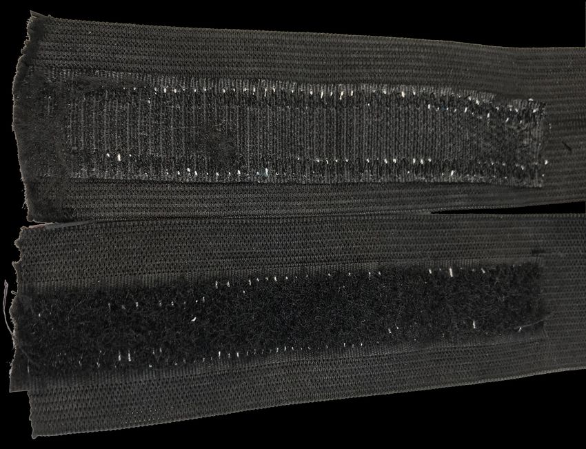
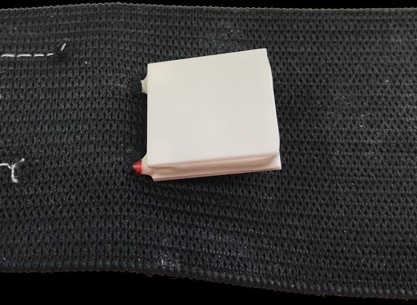
3.4 Piece of the stretchband sewn to the head-
band as a bag for the vibration motor. . . . . 15
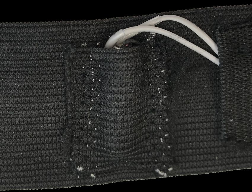
3.5 Pieces of the stretchband sewn to the head-
band as wireway for better cable management. 15
3.6 The botton and the 3D printed case. To be
pressed by the user when he recognizes feed-
back. . . . . . . . . . . . . . . . . . . . . . . . 16
3.7 Waterproof join of wires from each actuator
to the ribbon cable. . . . . . . . . . . . . . . . 17
3.8 The Arduino controlling the relay and other
components of the prototype via the ribbon
cable. The batteries power the theromelectric
cooler when the relay is set correspondingly. 18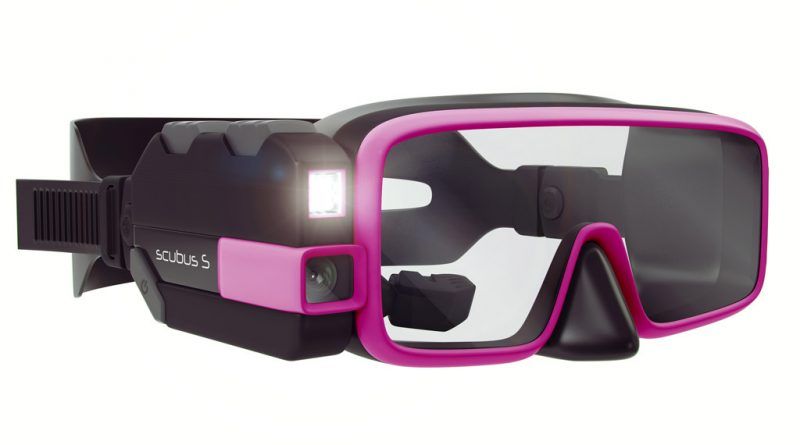
viii                                                  List of Figures

       3.9   Headband, diving goggles, and waterproof
             headphones with the integrated LED, Vibra-
             tion motor, and Thermoelectric cooling mod-
             ule. . . . . . . . . . . . . . . . . . . . . . . . .   19

       4.1   A participant during the study in a local
             swimming hall. . . . . . . . . . . . . . . . . .       24

       4.2   Results of the reaction time on different feed-
             back types under water. Means and 95% con-
             fidence intervals. . . . . . . . . . . . . . . . .     25

       4.3   Means and standard deviations (less is bet-
             ter) of the results from the questionnaire. . .        26

       4.4   Rating of the feedback modalities by the
             users (less is better). Means and 95% confi-
             dence intervals of the results from the ques-
             tionnaire. . . . . . . . . . . . . . . . . . . . . .   26

       4.5   Results of the reaction time on different feed-
             back types ashore. Means and 95% confi-
             dence intervals. . . . . . . . . . . . . . . . . .     29
ix List of Tables
xi

Abstract

A lot of research is going into underwater global positioning systems since radio
waves do not propagate underwater. However, the few underwater navigation ap-
proaches out there use bulky screen devices which are held in hand. This leads to
constrained movement, is rather distractive, and prone to varying brightness con-
ditions. In this master thesis we describe the construction of a prototype, which
incorporates several feedback methods, and its evaluation. We implement a vibra-
tion motor, a red LED, and a thermoelectric cooler in diving goggles and a head-
band. Additionally waterproof in-ear headphones are used for auditory feedback.
Since these devices are worn on the head they allow an unintrusive way to give low
level directional cues. In a user study we evaluate the feedback methods ashore as
a baseline and compare it to their performance underwater and gather additional
qualitative feedback of the participants.
xii Abstract
xiii

Überblick

Global Positioning Systeme für Navigation unter Wasser ist ein aktuelles
Forschungsgebiet, da Radiowellen unter Wasser nicht übertragen werden. Die
wenigen Systeme, die Unterwassernavigation zu einem gewissen Level umsetzen,
nutzen Bildschirme, die in der Hand gehalten werden. Das schränkt die Bewe-
gungsfreiheit ein, ist eher ablenkend und die Sichtbarkeit ist beeinflusst durch die
sich ändernden Lichtverhältnisse. In dieser Masterarbeit wird die Konstruktion
eines Prototypen beschrieben, der verschiedene Feedbackmethoden beinhaltet und
deren Auswertung. Wir benutzen einen Vibrationsmotor, eine rote LED und ein
Peltier Element in einer Taucherbrille und Stirnband. Zusätzlich verwenden wir
wasserfeste In-Ohr-Kopfhörer für akustisches Feedback. Da diese Geräte direkt
am Kopf getragen werden, ermöglichen sie einen unaufdringlichen Wege Rich-
tungsangaben auf niedrigem Level zu vermitteln. In einen Benutzerstudie werten
wir die verschiedenen Feedbackmethoden an Land aus und vergleichen die Leis-
tung mit der unter Wasser. Zusätzlichen sammeln wir qualitatives Feedback der
Teilnehmer.
xv

Acknowledgements

First of all, I would like to thank Prof. Dr. Jan Borchers for supervising my thesis
and Dr.-Ing. Ulrik Schroeder for being my second examiner. Secondly, I would like
to thank Jan Thar for her feedback and guidance. Furthermore, thanks to everyone
who participated in the time-consuming user study.
xvii

Conventions

Throughout this thesis we use the following conventions.

Text conventions

Definitions of technical terms or short excursus are set off
in coloured boxes.

 E XCURSUS :
 Excursus are detailed discussions of a particular point in
                                                               Definition:
 a book, usually in an appendix, or digressions in a writ-
                                                               Excursus
 ten text.

Source code and implementation symbols are written in
typewriter-style text.

myClass

The whole thesis is written in Canadian English.

Download links are set off in coloured boxes.

                                           File: myFilea
    a
        http://hci.rwth-aachen.de/public/file number.file
1 Chapter 1 Introduction Today navigation systems are a natural part of our every- day life. They are used in vehicles and every smart phone has GPS and map information as well. GPS uses 29 satel- lites in the atmosphere where at least four of them are in view from any spot on the earth at any time. The satel- lites are synchronized by control stations around the globe using atomic clocks. The receiver triangulates the position with the distance information of the satellites. Most of the time this navigation information is conveyed visually by a screen or auditory with precise instructions. Underwater navigation can be as crucial as it is outside the water. From novice snorkellers to experienced scuba (self- contained underwater breathing apparatus) divers naviga- tion information can lead to a better experience or is essen- tial for the task. Novice divers have no knowledge of the area and are not used to the orientation via certain land- marks. GPS underwater can help to navigate the user to points of interest, save locations to share them later, find back to the start, or view the route later on the computer. GPS underwater is a complex topic since the signals of GPS satellites do not propagate below the water surface. Cur- rent research investigates different approaches to provide GPS underwater not only for divers but submarines and autonomous underwater vehicles (AUV). A few systems are out there which already use a floating GPS antenna
2                                                1   Introduction

    wired to a screen held by the diver [Nehowig, 2014]. An-
    other system uses an initial GPS position before submerg-
    ing and switches to inertial sensor measurements while
    submerged [Ariadna Tech, 2016]. Using acoustic waves in
    analogy to the radio waves of the GPS satellites is locally
    used in WaterLinked [WaterLinked, 2018] and researched
    [Taraldsen et al., 2011].

    These systems, partly commercially available, focus on
    their realization of the GPS problem. All of them use wa-
    terproof encapsulated screens and controls which are held
    by the user all the time. On one hand, screens are a rich
    solution and can provide detailed information not only for
    navigation. On the other hand it can be tedious to carry a
    screen device all time, including the wires and high power
    consumption. Other solutions which focus more on the in-
    teraction part of underwater navigation systems propose
    augmented reality diving goggles [N. Smith, 2015]. It is an
    all in one system which is most likely expensive and not
    suitable for everyone.

    Since underwater GPS is hard to deploy without a proper
    test environment we decide to focus on the interaction as-
    pect. Following the concept of ubiquitous computing we
    aim to make the technology invisible to achieve high ac-
    ceptance and less distraction [Weiser, 1993]. Therefore, we
    focus on low level feedback which can give directional cues
    using more affordable electronics.

    In this thesis we present our prototype comprising an LED,
    a vibration motor, a Peltier cooling element, and water-
    proof headphones. We describe how it is built and what
    consideration it implies. Furthermore we conduct a user
    study with 10 participants testing the system underwater
    and one participant outside the water for comparison. We
    evaluate for the time it takes the participants to perceive the
    feedback by and ask for qualitative feedback via a question-
    naire and comments.

    The results show that light, vibration, and sound achieve
    rather similar reaction times. Thermal feedback performs
    poorly underwater and is not even recognized by all par-
    ticipants. Additionally, the power consumption of the ther-
3 moelectric cooler is not reasonable in mobile environments. Qualitative feedback supports the data of the study that vi- bration feedback is recommended to convey low level di- rectional cues underwater since it unobtrusive, well recog- nizable, and comfortable.
5

Chapter 2

Related work

In this chapter we give an overview of related work and re-
search in the the fields of underwater navigation systems.
It is divided into three parts. First we give an overview
of currently used technology used for underwater position
tracking and the issues in comparison with common GPS.
Second it covers existing systems which incorporate posi-
tion tracking and underwater feedback today and third re-
search regarding several feedback modalities.

 It is commonly known that radio signals do not propagate      Military grade
underwater. Current state of the art solutions consists of     underwater
large and expensive inertial measurement units. Those are      navigation
for example used in submarines and take the last known
position in combination with military grade accelerometer
and diving depth to interpolate the current location [Meyer,
2016].

 Rossi et al. [2014] presented a data fusion algorithm for     Inertial Data Fusion
inertial navigation with focus on performance. It is based
on the idea of data fusion which measures and combines
values from several inertial sensors.

 Taraldsen et al. [2011] technology relies on acoustic waves   Acoustic GPS
as an analogy to the GPS radio waves. They discuss differ-
ent approaches of Dilution Of Precision (DOP) which differ
from the classical GPS setting. Using statistical methods,
they estimate the accuracy of positioning and try to correct
6                                                              2   Related work

                   errors.

                   2.1       Underwater Navigation Systems

       Navimate     Shb Instruments [2009] developed Navimate which uses
                   a floating radio antenna for GPS and several underwa-
                   ter transducers to communicate with a wrist-worn device
                   via acoustic signals. The device receives the signals and
                   uses the information of the GPS and the transducers to de-
                   termine its location and presents the information on the
                   screen.

        NavDive     Nehowig [2014] built NavDive which uses a floating GPS
                   receiver wired to a mobile receiver held by the diver. It
                   shows the direction to previously set locations and posi-
                   tional information in text form. A desktop application lets
                   the user inspect their diving path and add landmarks for
                   locations of interest.

    Ariadna Tech    Ariadna Tech [2016] developed a system which uses an ini-
                   tial GPS location from the wrist unit before submerging and
                   switches to inertial sensors afterwards. The sensors track
                   the divers real-time position, speed, heading, and distance
                   information using a navigation transmitter worn on the leg.
                   It calculates the information in and sends it wirelessly to to
                   the wrist unit which displays it on screen.

    WaterLinked     WaterLinked [2018] uses four hydro acoustic receiver in the
                   water connected to a base station with access to a GPS an-
                   tenna. The tracked object or diver is equipped with a loca-
                   tor which acts as an beacon sending acoustic pulses. These
                   acoustic pulses are received be the four hydrophones and
                   analysed with time-of-arrival and the GPS data. This sys-
                   tem enables tracking of submerged ROVs and divers but
                   not for the divers themselves.

       Scubus S     N. Smith [2015] propose a system similar to featuring a
                   head up display like Google Glass, a LED flash light, and
                   a HD camera. All electronics including the battery are in-
                   tegrated into the smart diving goggles. The image is pro-
2.2 Feedback modalities 7 Figure 2.1: Scubus S smart diving goggles by Noah Smith. jected into the eye of the user. The system is shown in fig- ure 2.1 2.2 Feedback modalities Bosman et al. [2003] built and tested a system using two GentleGuide wrist worn vibration devices. Main findings were that vi- bration feedback on one wrist is confusing, vibrations are rather a beacon to follow than a correction of one’s direc- tion, and that direction is better encoded in the duration of the pulse than the intensity. Results are promising for non- disruptive, easy learnable, low level navigation cues. Kiss et al. [2018] present MOtorbike VIbrational Naviga- MOVING tion Guidance, a smart kidney belt for motor cyclists that provides feedback through 12 vibration motors. Tactile feedback allows distraction free navigation cues which are more reliable and safe than visual based navigation systems used today. Kaul and Rohs [2016] developed HapticHead a system for HapticHead intuitive tactile 3D guidance. The use 20 vibration motors in 3 concentric ellipses around the head to give 3D direc- tional cues in virtual or augmented reality environment. Vibration performed well compared to direct visual guid- ance and significantly better than 3D auditory cues.
8                                                                      2   Related work

             IrukaTact     IrukaTact by Chacin and Oozu [2016] is a a glove which
                          uses water propulsion on the fingertips and a sonar to as-
                          sist in the location of objects underwater. The sonar detects
                          the topography of the ground and sends the information to
                          the system which uses micro-pumps to convey these infor-
                          mation via varying water jets on the fingertips.

           ThermoVR        Peiris et al. [2017] present ThermoVR, a VR headset with
                          five thermal feedback modules. The thermal stimulation,
                          hot and cold, were used to increase the immersion and
                          give directional cues. They found that cold stimuli were
                          perceived significantly better in providing directional feed-
                          back.

    Cold vs hot stimuli    Wilson et al. [2011] discovered that cold stimuli are faster to
                          detect and more comfortable for the user. They tested dif-
                          ferent changes of temperature per second and higher rates
                          are better detectable. Also producing detectable cold stim-
                          uli are more power efficient than warm stimuli.

     Effect of ambient     Halvey et al. [2012b] investigated the environmental ef-
          temperature     fects on thermal feedback recognition. They conducted an
                          outdoor study over several month with varying conditions
                          and showed that ambient temperature has a significant ef-
                          fect on the detection and perception of thermal stimuli. Hu-
                          midity on the other hand has a negligible effect in mobile
                          interaction. This result is supported by Givoni et al. [2006].

    Effect of room and     Hirosawa et al. [1984] looked into the effect of room and
     skin temperature     skin temperature on sensitivity. Their results show that
                          the threshold values change with the room temperature for
                          both, warm and cold.
9 Chapter 3 Hardware Prototype and Software In this chapter we present the construction of the hard- ware prototype and development of the user study soft- ware. Furthermore we talk about the technical consider- ations regarding each component and their feasibility. 3.1 System Design The aim of this thesis is to investigate the perception of sev- eral feedback modalities underwater and their feasibility for low level navigation cues. We include visual, auditory, and tactile feedback in form of a LED, waterproof in ear headphones, a vibration motor, and a thermoelectric cool- ing module. The prototype has to incorporate these meth- ods as unobtrusive and comfortable as possible in particu- lar when they are inactive. Electronic connections have to be waterproof, undisturbing, and fail safe. Furthermore all components should be affordable to provide an advantage over commercial solutions. To investigate the recognition times and comfort of each technique we built a prototype composed of one LED in the diving goggles as well as a waterproof vibration mo-
10                       3   Hardware Prototype and Software

     tor and a Peltier cooling module in a stretchable headband.
     The headphones are provided separately.

     Visual Feedback To provide visual low level feedback we
     use a common red 5 mm LED. An issue regarding lumi-
     nous light emitted by an LED is its proneness to water re-
     flections. These reflections change rapidly due to water un-
     dulation and exterior lighting. The color of the surround-
     ings influence it as well. For example light blue tiles in a
     swimming pool render a blue LED almost undetectable. To
     provide clear recognizable feedback we tested several col-
     ors underwater and came to the conclusion that red LED is
     better recognizable than other common LED colors.

     There are several ways to provide feedback with an LED.
     Depending on the way it is presented the user might not
     notice it fast enough if the brightness increases over time.
     However, this might be more comfortable than turning on
     the LED to full brightness instantly. Therefore we imple-
     ment both. First we set the LED from zero to full brightness
     immediately. Second we increase the brightness from 0% to
     100% and back to 0% over 5.1 seconds resulting in a slowly
     blinking pattern. We choose this interval arbitrarily after
     testing several duration. This can be further investigated
     but would go beyond the scope of this thesis since we aim
     to consider several modalities.

     Auditory Feedback For auditory feedback we choose
     AGPTEK E11B IPX8 waterproof in-ear headphones. The
     headphones are worn separately from the other compo-
     nents and are connected to the operating MacBook Pro.
     Like visual feedback, the comfortableness of auditory feed-
     back depends on the way it is presented to the user. The au-
     dio file played should start immediately and be clearly rec-
     ognizable. Furthermore the pitch and loudness should be
     within an appropriate range. We use the sound of a sonar
     since it suits the underwater scenario.

     Vibration Feedback To provide feedback using vibration
     actuators we choose waterproof 7 mm vibration motors.
3.1 System Design 11 They are working at 3.3 V with 2.45 g at 250 Hz. We tried to make smaller vibration motors waterproof. Using shrink- ing tubing and epoxy resin adhesive made them water- proof but running them over night underwater let them stop working regardless. Thus we have to stick to the larger motor. We handle the vibration feedback similar to the visual feed- back and set it to maximum power instantaneously as well as increasing it over time. Tests have shown that it requires a certain amount of voltage to feel a vibration even outside the water. Therefore we start at 1,18 V, where vibration is barely noticeable, and increase to 3.3 V over 5.4 seconds. Literature suggests to place tactile feedback at the shoul- ders or the hips [Kiss et al., 2018]. Since we aim to build a compact prototype we implement the vibration motor in the headband instead of an separate belt which would in- clude more wires. Additionally we think that especially while snorkeling the users want an unobtrusive experience. Thermal Feedback For thermal feedback we choose a CUI CP6014 Thermoelectric Module. Peiris et al. [2017] have shown that users prefer cooling over heating. Cool- ing also performs better when it comes to recognition time. Previously we tested heating and cooling effects in water with 21 degrees and cooling was much faster perceivable than heating. Additionally heating effects were rarely rec- ognizable. The theromelectric cooler has a maximum volt- age of 2.1V and maximum current of 6 A. Therefore we use an external battery combined with a relay to operate it. There are specific circuit boards to control the temperature of theromelectric cooling elements. However, we consid- ered that running it on full power is sufficient for our pur- pose since we are interested in the fastest possible reaction times underwater.
12                        3   Hardware Prototype and Software

     Figure 3.1: LED insulated and attached between the sili-
     cone and frame of the diving goggles using hotglue.

     3.1.1   Hardware Prototype

     As shown in figure 3.1 the LED is glued to the diving gog-
     gles between the silicone and the frame. There are three rea-
     sons to place the LED there. First, the LED is not in sight or
     noticeable when turned off and thus unobtrusive. Second,
     the light is diffused by the silicone leading to non-dazzling
     feedback. Third, the cable routing is easier compared to
     placing it within the silicone and still make sure no water
     gets in.

     In addition to the stretchability of the headband it feature
     a pair of hook and loop fastener as shown in figure 3.2.
     Both parts of the fastener are 12 cm long allowing align-
     ment of headband length from approximately 38 up to 62
3.1 System Design 13 Figure 3.2: Stretchable headband with hook and loop fas- tener sewn to it. Allows comfortable adjustment on differ- ent head froms and sizes. cm (stretching not included). This enables adjustable, tight, and still comfortable wear of the headband. The fasteners were sewn to the 40 mm wide elastic band using a Bernina 880. To sense the cooling effect of the thermoelectric module it has to be placed directly onto the users skin. We achieve this by cutting two holes in the elastic band and put the VCC and Ground wires through it. Although the edges of the module seem to be uncomfortable, none of the users noticed it at all while it was not active. The heat produced by the theromelectric cooler is no issue underwater since the water naturally conducts the heat away. As depicted in figure 3.4 a piece of the elastic band was sewn to the headband to house the vibration motor. Since we choose an already waterproof vibration motor the only challenge is to keep the motor in place and still provide as much tactile performance to the user as possible. Therefore the the piece of elastic band is sewn to the headband to be at maximum stretch when the motor is in the bag. The ki-
14                        3   Hardware Prototype and Software

     Figure 3.3: theromelectric cooler mounted to the headband
     to be placed directly on the users skin.

     netic energy is better transferred by rigid objects. As for
     the theromelectric cooler, the motor is not perceived by the
     user wearing the headband while it is turned off.

     To prevent the user form tangling up in the wires we sew
     pieces of the elastic material to the headband as shown in
     figure 3.5. These wireways, leading to one side of the head-
     band, make wire management easier and prevent them
     from being damaged.

     The user has to provide feedback if she notices one of the
     possible stimuli we present to her. Figure 3.6 shows the but-
     ton we use for this purpose. We pick a large button used
     in arcade cabinets and a 3D printed case. The button fea-
     tures vertical lift to prevent accidental pressing by the user.
     Furthermore, the supervisor can hear a clearly recognizable
     click sound when the button was pressed which helps mon-
     itoring the functionality of hardware and software. A con-
     sequence of this button design is that the user has to press
     it outside the water. This is no issue since the user will stay
     at the pool edge anyway.

     The wires of the LED, vibration motor, theromelectric
3.1 System Design 15 Figure 3.4: Piece of the stretchband sewn to the headband as a bag for the vibration motor. Figure 3.5: Pieces of the stretchband sewn to the headband as wireway for better cable management.
16                        3   Hardware Prototype and Software

     Figure 3.6: The botton and the 3D printed case. To be
     pressed by the user when he recognizes feedback.

     cooler, and botton are joined with a ribbon cable depicted
     in figure 3.7. All connections and soldering joints are made
     waterproof with glue and shrinking tube. The 3 m long
     ribbon cable leads to the breadboard shown in figure 3.8.
     The breadboard houses an Arduino Uno, the cables lead-
     ing form the pins to the ribbon cable, a relay, and a battery
     case. The relay is connected to the Arduino Uno which con-
     trols when it connects the two AA batteries with the Peltier
     circuit. Figure 3.9 shows all prototype parts worn by the
     user.
3.2 Software 17 Figure 3.7: Waterproof join of wires from each actuator to the ribbon cable. 3.1.2 Safety Since we operate electronics in an underwater test environ- ment, safety concerns arise. In fact, the voltage and current are below critical values. Besides, all wired connections are waterproof and tested for three days in a box filled with water. The breadboard is always placed in some distance and above the water surface. During the operation of the prototype in underwater scenario the breadboard and bat- teries are loosely covered by a towel to protect it against splashing water. In case the user leaves the pool edge the ribbon cable falls off the breadboard rather than pulling it down. We achieve this with shorter than usual pin header connections. 3.2 Software The software for the prototype and the user study runs partly on the Arduino Uno micro controller and partly on a computer. The micro controller activates the feedback el- ements or signals the computer via processing to play a sound file. Furthermore it tracks the time a user needs to
18                        3   Hardware Prototype and Software

     Figure 3.8: The Arduino controlling the relay and other
     components of the prototype via the ribbon cable. The bat-
     teries power the theromelectric cooler when the relay is set
     correspondingly.

     press the button after the feedback was activated and sends
     that date to computer. Processing receives the data frames
     from the micro controller and creates a file to log the data
     for further analysis or plays the sound file and tracks that
     time.

     Arduino Code Each stimulus (increasing LED, LED, in-
     creasing vibration, vibration, sound, theromelectric cooler)
     is exclusively encoded with a number from 0 to 5. Six dis-
     tinct arrays were randomly generated only limited by pro-
     hibiting occurrences of the same stimuli in a row more than
     two times and by making sure each stimuli is active exactly
     8 times. This results in 48 stimuli per program run. The ran-
     dom generation of the arrays is used to prevent participants
     from recognizing the order of the stimulus which might in-
     fluence the results. It has been done in a separate program
     due to an inefficient algorithm which would slow down the
     user study program unnecessarily.

     The program iterates over the array and a switch case state-
     ment that triggers the corresponding actions. For each ac-
     tion the time is saved in milliseconds immediately before
3.2 Software 19 Figure 3.9: Headband, diving goggles, and waterproof headphones with the integrated LED, Vibration motor, and Thermoelectric cooling module. the stimulus is activated. The program proceeds with the current action until the button is pressed and the start time is subtracted from the end time. Results are sent in a for- mat which specifies whether data (D) follows, the sound file (S) has to be played, or an interrupt (I) via a button press was issued after the sound file was played. This is followed by the identification number of the action. Thereupon fol- lows the time (t) in milliseconds and an x to terminate the frame or just the x if it is not data. Tracking the time of the sound is done on the computer. For example a data frame after the LED action is completed in 0.45 seconds looks like D3t450x, a play-sound frame like S5x, and when the button was pressed while the sound file is playing like Ix. After each action is completed the program waits for two seconds and additionally a random number of seconds be- tween zero and five before the next action triggers. This is done to further prevent adoption to a rhythm which influ- ences the measurements. Once the 48 actions are completed Fx is sent and the program enters an infinite loop. Processing Code In Processing we create a Writer which creates and writes to a text file for logging the user study data. Furthermore a sound file is loaded to be played when
20                         3   Hardware Prototype and Software

     the corresponding signal from the micro controller arrives.
     Processing reads the incoming data from the micro con-
     troller per character and saves it in an array of characters. If
     x is read, the serial port is cleared and the data handling be-
     gins. In case of a data transmission for the LED, vibration
     motor, or theromelectric cooler, the identification number
     of the current stimulus and the corresponding time is writ-
     ten to the log file. If S is received the sound file is played
     and the time is saved. After pressing the button, playback
     of the sound file stops and the time taken is calculated and
     written to the logfile. After handling the data the buffer is
     cleared and the next data frame can be received. When the
     micro controller sends F to signal the end of the program
     the log file is saved.

     3.2.1   Testing

     Hardware testing To ensure the functionality of the pro-
     totype underwater and over a longer period of time testing
     is required. This is particularly important since the supervi-
     sor of the study can not tell if the prototype works properly
     while the participant is submerged. In advance of assem-
     bling the prototype we tested each component individually
     for several days. The corresponding modes for each modal-
     ity were activated in intervals similar to the user study pro-
     gram. As mentioned in 3 we tested some vibration mo-
     tors which were not suited for our needs. Repeated tests
     have shown that the small and cheaper vibration motors
     break after running them even outside the water. However
     higher quality vibration motors in the same small order of
     magnitude seem promising. Since the already waterproof
     vibration motors passed the test we went with those for the
     sake of convenience. All other components passed the test-
     ing without errors.

     Measurement accuracy Since we measure in milliseconds
     and feedback is partly recognized in under one second we
     must ensure the measurements are correct. To ensure high
     accuracy we tested each modality and the communication
     latency itself. Communication latency is not measurable
3.2 Software 21 within the millisecond range. The sound file is cut such that it starts with a clearly audible noise level from the be- ginning. Measuring a single playback of the file reveals that there is a short delay of about 2 milliseconds. This delay can be considered redundant. Besides it is influenced by the hardware which reads and plays the file and the file size it- self. To reduce the delay of the vibration motor to the same magnitude we let the vibration motor run with low rotation which is not noticeable. The increasing motor action starts precisely at an intensity which is barely noticeable outside the water. Activating the LED has no measurable delay in the millisecond range.
23

Chapter 4

Evaluation

In this chapter we will evaluate our prototypes with respect
to the quantitative and qualitative aspects of the different
feedback methods. We are interested to what extent the per-
ception of feedback differs onshore versus underwater re-
garding time until the stimulus is perceived. We conducted
a user study consisting of two parts: in the first part we
measured reaction times between presentation of the feed-
back and it being perceived by the user. The second part
was a questionnaire investigating preferences and experi-
ences regarding the feedback types and their applicability
for navigation under water.

4.1   User Study

The apparatus consists of a button at the edge of the pool,
diving goggles with an LED on the right side, a headband
with a vibration motor and a thermoelectric cooler (TEC),
and waterproof in-ear headphones. These are encapsulated
and connected to an Arduino Uno except for the head-
phones which are directly connected to the MacBook Pro.
The Arduino measures the time between the activation of
a feedback and the press of the button. For sound the Ar-
duino sends the command to Processing which then plays
the Sound file and measures the reaction time. Processing
24                                                 4   Evaluation

     Figure 4.1: A participant during the study in a local swim-
     ming hall.

     logs the time in milliseconds and the corresponding feed-
     back for further analysis.

     4.1.1   Procedure

     The participants took a shower and were asked to swim
     a few laps until they felt at ease. They put on the diving
     goggles and the headband first, and we ensured that the
     peltier element had direct contact to the skin of the forehead
     and that the headband was worn firmly and comfortably.
     Finally, participants put on the snorkel and the earphones.
     Then the participant was instructed to submerge, start the
     study by pressing the button for the first time, and press the
     button as soon as she perceives a stimulus. The prototype
     is shown in figure 4.1.

     Every run included each stimulus eight times in random
     order with the same stimulus being repeated at most two
     times in a row. After the button was pressed the next stim-
     ulus was randomly delayed between two and eight seconds
     to prevent adaption. This was repeated at least four times
     per participant with some participants voluntarily doing
     more runs. Participants were allowed to emerge whenever
     they feel uncomfortable or had issues with the equipment.
     Afterwards, participants answered questions on a 5-point
     Likert scale regarding feedback recognition, feedback com-
4.1 User Study 25 Figure 4.2: Results of the reaction time on different feed- back types under water. Means and 95% confidence inter- vals. fort, and imagining the feedback type for underwater nav- igation. The equipment is cleaned with sanitizer after usage. When acquiring the participants the were allowed to bring their own snorkel if the have hygienic concerns. 4.1.2 Design The independent variable was STIMULUS (simple LED, pulsing LED, vibration, increasing vibration, cooling, Sound). A sequence of eight stimuli of each type in ran- dom order for each run and at least 4 runs per user resulted in (6 x 8 x 4) 192 trials per user in a within-subjects design (48 trials for every additional run). The dependent variable is Time [ms] which denoted the time between a stimulus started and the button was pressed. 4.1.3 Results A total of 10 users participated in the study (average age 24.1, 8 male), five of which had prior experience with div- ing or snorkeling. 391 outliers (results differed by more than 1.5 SD from the mean) were identified resulting in 2021 data points. The results of the reaction time are shown in figure 4.2. Only 4 participants recognized the thermoelec- tric cooler at all which led to the majority of outliers. The
26                                                  4   Evaluation

     Figure 4.3: Means and standard deviations (less is better)
     of the results from the questionnaire.

     Figure 4.4: Rating of the feedback modalities by the users
     (less is better). Means and 95% confidence intervals of the
     results from the questionnaire.

     remaining outliers are caused by issues with the equip-
     ment (e.g., water in the snorkel or goggles), forcing the
     participant to emerge. We log-transformed Time for a re-
     peated measures ANOVA. STIMULUS had a significant ef-
     fect on Time (F 1991 = 852.97, p < .0001). Tukey HSD
     post hoc pairwise comparisons showed that the thermoelec-
     tric cooler (4580ms) was significantly slower compared to
     each other STIMULUS and pulsing LED (615 ms) was sig-
     nificantly slower than vibration (458 ms) and simple LED
     (384ms).

     We used Friedman and Wilcoxon Signed Ranks tests to
     evaluate the questionnaire (cf. Figure 4.3). There was a sig-
     nificant difference in user rated recognition (χ2 (5) = 39.73,
     p < .001). Post-hoc pairwise comparison revealed that the
     thermoelectric cooler was perceived significantly less than all
     other stimuli (p < .005).
     There was a significant difference in user rated comfort
     (χ2 (5) = 15.83, p < .007). Post-hoc pairwise comparison re-
     vealed that thermoelectric cooler was significantly less com-
4.1 User Study 27 fortable than all other stimuli (p < .041) and increasing vi- bration was significantly more comfortable than vibration (p < .046). There was a significant difference in user rated navigation suitability (χ2 (5) = 28.77, p < .001). Post-hoc pairwise comparison revealed that only the thermoelectric cooler was rated significantly less suitable for underwater navigation (p < .004). 4.1.4 Discussion The results and the tremendous power consumption show that the thermoelectric cooler is not suitable for underwa- ter applications. Participants reported that it is hard to tell whether the thermoelectric cooler is active or if it is a cold flow of water. The skin adapts to thermal changes quickly and makes consecutive cooling events hard to de- tect [Halvey et al., 2012a]. Visual, vibrotactile, and auditory stimuli are suitable for underwater navigation regarding reaction time (384 - 615 ms). Even though the LED feedback was fastest (384 ms) the vibration (459 ms) was perceived to be recognized faster. Binary feedback using light and vibration was per- ceived as less comfortable than the fading counterparts. Therefore, in an underwater navigation scenario, instant feedback should be used for time critical events only. Oth- erwise the more comfortable stimuli suffice. Participants commented that LED feedback can be mis- taken for water reflections or to be obstructive and dis- tracting. Sound was rated as being immediately perceiv- able (1.0), but some users felt uncomfortable wearing in- ear headphones under water. Vibration on the other hand uses a different sense which is not occupied while div- ing/snorkelling and provides clear and comfortable feed- back. Moreover, the vibration feedback is not influenced by light reflection or water temperature. Furthermore vibra- tion feedback acts like bone conductance Sound, and there- fore, also includes additional auditory feedback.
28                                                 4   Evaluation

     4.1.5   Testing outside the water

     We let one user test the prototype outside the water to get
     a rough estimate how the medium influences the results in
     general. This user is sitting on a table and wears the proto-
     type including the diving goggles but without the snorkel.
     The relay we use makes a notable clicking noise which is
     audible through the headphones worn by the participant.
     Therefore we use a pillow and a wastebin to make it infra-
     sonic. Again we let the user do as many trials as she was
     willing to do. 210 trials are carried out by the user. Other
     than that the procedure and the user study program remain
     the same as described above.

     The results of the participant is shown in figure 4.5. It
     is immediately notable that the visual stimulus is on av-
     erage faster received in the under water condition (LED:
     69.285 ms, Pulsing LED: 81.708 ms). Contrarily to the vi-
     sual modality on average the haptic feedback of the vibra-
     tion motor is faster perceived outside the water (Vibration:
     28.822 ms, Increasing Vibration: 109.135 ms). The most pre-
     eminent difference between the two mediums is measured
     when it comes to thermal feedback. Not only is the cool-
     ing effect of the thermoelectric cooler recognized reliably
     by the participant, but also 3152.580 ms faster with 1427.657
     ms. Sound was perceived negligibly faster underwater with
     19.339 ms difference.

     A reason for the slightly better performance of the LED un-
     derwater can be explained by the fact that underwater the
     participants is facing the pool edge where the participant
     testing the system outside the water has more objects in the
     room to possibly look at. However, the differences for LED,
     Vibration, and Sound might adjust when testing with more
     users ashore. In contrast, the water has a significant influ-
     ence on the sensibility of the cooling effect provided by the
     thermoelectric cooler.
4.1 User Study 29 Figure 4.5: Results of the reaction time on different feed- back types ashore. Means and 95% confidence intervals.
31

Chapter 5

Summary and future
work

5.1    Summary and contributions

We built and tested a prototype to investigate the applica-
bility of four feedback modalities for the low-level under-
water navigation context. The prototype consists of diving
goggles with an LED glued to it, a stretchable headband
with a thermoelectric cooling element and vibration motor,
a snorkel, and the electronics including an Arduino Uno.
Visual, tactile, thermal, auditory feedback was investigated
for their perceptibility and comfort in underwater scenario.

Results have shown that thermal feedback is not well suited
for underwater application since it was not recognizable by
a large amount of participants in the first place. It is heavily
influenced by the water and perceptibility varies depend-
ing on the water temperature. This, however, was not ob-
served outside the water where only the technical limita-
tions of the thermoelectric cooler prolongates the recogni-
tion by the user. Additionally the huge amount of power
used by the peltier cooling element makes it impractical to
use in mobile environment.

Visual, vibration, and auditory feedback was perceived
32                                5   Summary and future work

     well and technically suited to provide underwater navi-
     gation cues. Qualitative analysis via a questionnaire, an-
     swered by the participants, revealed that vibration feed-
     back performs best on a subjective level. It does not occupy
     any of the senses which used for diving in contrast to the
     LED. Some users report that wearing the waterproof in-ear
     headphones was uncomfortable and that they are not used
     to wear those underwater.

     5.2   Future work

     Our study solely focused on how fast the respective feed-
     back can be perceived underwater and how comfortable it
     is. We did not yet investigate how accurate the feedback
     methods can communicate navigation cues in the field. In
     the future we will drop the thermoelectric cooler due to
     its bad performance underwater and massive power con-
     sumption. Furthermore we will tweak our prototype to
     incorporate a symmetrical amount of LEDs and vibration
     motors. The exact amount has to be investigated with a
     separate user study.

     Since the vibration feedback on the head might have an in-
     fluence on the comfort in the long term, we suggest to im-
     plement the vibration motors directly in the diving equip-
     ment of scuba-divers. Well accepted locations were investi-
     gated by Kiss et al. [2018].

     Accuracy of the navigation cues is the most interesting
     measurement after proving the perceivableness. To com-
     pare the performance of low level cues and more sophis-
     ticated approaches, like augmented reality diving goggles
     and precise auditory instruction via bone conduction head-
     phones, further investigation in real world scenarios will be
     conducted.

     To conduct studies in the field the prototype will be made
     wireless. The primary challenges will be the waterproof
     incorporation of the power supply and electronics as well
     as establishing precise measurements. The omission of real
     time observation and communication requires technology
5.2 Future work 33 presented in chapter 2. Furthermore a reasonable way to provide 3D navigation cues has to be investigated with fo- cus on comfort and accuracy similar to HapticHead by Kaul and Rohs [2016].
35

Appendix A

TITLE OF THE FIRST
APPENDIX

                          File: Source Code and Resultsa
  a
    http://hci.rwth-aachen.de/public/UnderwaterNavigation/Comparing   Feedback   Tech-
niques for Navigation Underwater.zip
37 Bibliography Inc. Ariadna Tech. Ariadna - empowering divers with un- derwater navigation, 2016. https://www.ariadna. tech/. S. Bosman, B. Groenendaal, J. W. Findlater, T. Visser, M. de Graaf, and P. Markopoulos. Gentleguide: An ex- ploration of haptic output for indoors pedestrian guid- ance. In MobileHCI ’03, 2003. ISBN 978-3-540-45233-1. doi: 10.1007/978-3-540-45233-1 28. A. C. Chacin and T. Oozu. Irukatact. interactions, 23(6), 2016. ISSN 1072-5520. doi: 10.1145/2991899. URL http: //doi.acm.org/10.1145/2991899. B. Givoni, J. Khedari, N.H. Wong, H. Feriadi, and M. Noguchi. Thermal sensation responses in hot, humid climates: effects of humidity. Building Research & Informa- tion, 34(5), 2006. doi: 10.1080/09613210600861269. M. Halvey, G. Wilson, S. Brewster, and S. Hughes. ”baby it’s cold outside”: The influence of ambient temperature and humidity on thermal feedback. In CHI ’12. ACM, 2012a. ISBN 978-1-4503-1015-4. doi: 10.1145/2207676.2207779. Martin Halvey, Graham Wilson, Stephen Brewster, and Stephen Hughes. ”baby it’s cold outside”: The influ- ence of ambient temperature and humidity on thermal feedback. In Proceedings of the SIGCHI Conference on Hu- man Factors in Computing Systems, CHI ’12, pages 715– 724, New York, NY, USA, 2012b. ACM. ISBN 978-1- 4503-1015-4. doi: 10.1145/2207676.2207779. URL http: //doi.acm.org/10.1145/2207676.2207779. I. Hirosawa, H. Dodo, M. Hosokawa, S.. Watanabe, K. Nishiyama, and Y. Fukuchi. Physiological variations
38                                                  Bibliography

       of warm and cool sense with shift of environmental.
       International Journal of Neuroscience, 24(3-4), 1984. doi:
       10.3109/00207458409089817.

     O. Kaul and M. Rohs. Haptichead: 3d guidance and target
       acquisition through a vibrotactile grid. In CHI EA ’16.
       ACM, 2016. ISBN 978-1-4503-4082-3. doi: 10.1145/
       2851581.2892355.

     F. Kiss, R. Boldt, B. Pfleging, and S. Schneegass. Nav-
        igation systems for motorcyclists: Exploring wearable
        tactile feedback for route guidance in the real world.
        In CHI ’18. ACM, 2018. ISBN 978-1-4503-5620-6. doi:
        10.1145/3173574.3174191.

     Robinson Meyer.      Gps doesn’t work under-
       water, 2016.      https://www.theatlantic.
       com/technology/archive/2016/06/
       its-gps-underwater-for-robots/486656/.

     A. L. N. Smith, B. Andrick.    Scubus s - gps-
       based underwater navigation technology, 2015.
       https://snorkelaroundtheworld.com/2015/
       05/smart-scuba-diving-mask/.

     Kelly Nehowig.     Navdive – gps-based naviga-
       tion for scuba divers, 2014.  https://www.
       kickstarter.com/projects/1889195857/
       navdive-gps-based-navigation-for-scuba-divers/
       ?ref=kicktraq.

     R. L. Peiris, W. Peng, Z. Chen, L. Chan, and K. Mi-
       namizawa. Thermovr: Exploring integrated thermal
       haptic feedback with head mounted displays. In CHI ’17.
       ACM, 2017. ISBN 978-1-4503-4655-9. doi: 10.1145/
       3025453.3025824.    URL http://doi.acm.org/10.
       1145/3025453.3025824.

     A. Rossi, M. Pasquali, and M. Pastore. Performance anal-
       ysis of an inertial navigation algorithm with dvl auto-
       calibration for underwater vehicle. In DGON Inertial Sen-
       sors and Systems (ISS), 2014. doi: 10.1109/InertialSensors.
       2014.7049481.

     Inc. Shb Instruments. Navimate - gps for divers, 2009.
       https://www.navimate.com/.
Bibliography 39 G. Taraldsen, T. A. Reinen, and T. Berg. The underwater gps problem. In OCEANS 2011, 2011. doi: 10.1109/ Oceans-Spain.2011.6003649. WaterLinked. Underwater gps explorer kit, 2018. https: //waterlinked.com/products/. M. Weiser. Some computer science issues in ubiquitous computing. Commun. ACM, 36(7):75–84, July 1993. ISSN 0001-0782. doi: 10.1145/159544.159617. URL http: //doi.acm.org/10.1145/159544.159617. G. Wilson, M. Halvey, S. A. Brewster, and S. A. Hughes. Some like it hot: Thermal feedback for mobile devices. In CHI ’11, 2011. ISBN 978-1-4503-0228-9. doi: 10. 1145/1978942.1979316. URL http://doi.acm.org/ 10.1145/1978942.1979316.
Typeset September 25, 2018
You can also read