Comprehensive Energy Renovation of Two Danish Heritage Buildings within IEA SHC Task 59
←
→
Page content transcription
If your browser does not render page correctly, please read the page content below
heritage

Article
Comprehensive Energy Renovation of Two Danish Heritage
Buildings within IEA SHC Task 59
Jørgen Rose *            and Kirsten Engelund Thomsen

                                          Department of the Built Environment, Aalborg University, A C Meyers Vænge 15,
                                          DK-2450 Copenhagen SV, Denmark; ket@build.aau.dk
                                          * Correspondence: jro@build.aau.dk

                                          Abstract: Historic and heritage buildings present a significant challenge when it comes to reducing
                                          energy consumption to mitigate climate change. These buildings need careful renovation, and increas-
                                          ing their energy efficiency is often associated with a high level of complexity, because consideration
                                          for heritage values can often reduce and impede possibilities and sometimes even rule out certain
                                          improvements completely. Despite these issues, many such renovation projects have already been
                                          carried out, and therefore the IEA SHC Task 59 project (Renovating Historic Buildings Towards Zero
                                          Energy) in cooperation with Interreg Alpine Space ATLAS has developed a tool for sharing these
                                          best-practice examples—the HiBERatlas (Historical Building Energy Retrofit Atlas). The Internet
                                          serves as a best-practice database for both individual energy efficiency measures and whole-building
                                          renovation projects. This paper presents two of the Danish projects featured in HiBERatlas. The first
                                          project, Ryesgade 30, is a Copenhagen apartment building with a preservation-worthy period brick
                                          façade. The second project is the Osram Building, a listed Copenhagen office building from 1959 with
                                          a protected façade, which today acts as a culture centre. Both renovation projects achieved significant
                                energy savings and consequently CO2 -emission reductions, and the indoor climate in both buildings

                                          have also improved significantly. Furthermore, a detailed analysis was carried out regarding possible
Citation: Rose, J.; Thomsen, K.E.
                                          window solutions and ventilation systems in Ryesgade 30, and for the Osram Building regarding
Comprehensive Energy Renovation
                                          daylighting technologies. This paper investigates the two renovation cases through the available
of Two Danish Heritage Buildings
                                          measurement and calculation results before and after renovations and demonstrates that it is possible
within IEA SHC Task 59. Heritage
2021, 4, 2746–2762. https://
                                          to reduce energy consumption significantly and at the same time improve the indoor climate without
doi.org/10.3390/heritage4040155           compromising the cultural values of buildings.

Academic Editor: Tor Broström             Keywords: historic buildings; energy renovation; energy savings; HiBERatlas; IEA Task 59; best-practice
                                          database; indoor climate; daylight; windows; ventilation
Received: 14 July 2021
Accepted: 24 September 2021
Published: 28 September 2021
                                          1. Introduction
Publisher’s Note: MDPI stays neutral
                                               The European building stock accounts for approx. 40% of the total energy consumption
with regard to jurisdictional claims in
                                          in Europe [1]. In order to reduce this and thereby mitigate climate change, there is a need
published maps and institutional affil-
                                          for significantly increasing the energy efficiency of the existing building stock. In this
iations.
                                          respect, historic and cultural heritage buildings are special. They need careful renovation
                                          and restoration, and increasing their energy efficiency is often associated with a high level
                                          of complexity because consideration for heritage values can often reduce and impede
                                          possibilities and sometimes even rule out certain improvements completely. Lidelöw et al.
Copyright: © 2021 by the authors.         carried out a literature review on energy efficiency measures for heritage buildings, which
Licensee MDPI, Basel, Switzerland.
                                          clearly underlines this fact [2].
This article is an open access article
                                               Buda et al. [3] presented an approach to support decision makers in selecting relevant
distributed under the terms and
                                          retrofit solutions. Their paper focuses on best practices for walls, windows, HVAC systems
conditions of the Creative Commons
                                          and solar thermal and PV technologies and, as a main result, the paper encourages deci-
Attribution (CC BY) license (https://
                                          sion makers to opt for specifically tailored energy retrofits to solve the conflict between
creativecommons.org/licenses/by/
4.0/).
                                          conservation and energy performance requirements.

Heritage 2021, 4, 2746–2762. https://doi.org/10.3390/heritage4040155                                      https://www.mdpi.com/journal/heritage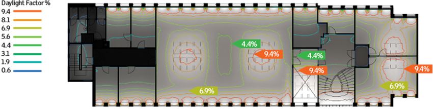
Heritage 2021, 4                                                                                            2747

                         Harrestrup and Svendsen have investigated the use of internal insulation in a heritage
                   building block with wooden beam construction and masonry brick walls as part of an
                   energy renovation. The risk of mould growth in the wooden beams and in the interface
                   between the insulation and the brick wall was evaluated, and it transpired that a 200 mm
                   gap in the insulation can be a moisture-safe solution for some orientations. It is not
                   recommended to apply internal insulation at thin walls towards north, and a 200 mm gap
                   in the insulation results in increased heating consumption of 3 kWh/m2 /yr. Energy-savings
                   of 39–61% were obtained, which was strongly influenced by occupant behaviour [4,5].
                         Rieser et al. [6] provided a systematic approach to pair appropriate ventilation system
                   solutions with historical buildings. The paper provided both a review and an overview
                   of the interrelationships between heritage conservation and the need for ventilation in
                   energy-efficient buildings, regarding building physics and indoor environmental quality.
                         Despite these issues, many renovation projects related to heritage buildings have
                   already been carried out and therefore it makes sense to promote some of the best-practice
                   examples that can serve as inspiration for, e.g., architects, building owners and people
                   involved in heritage protection. To this end, the IEA SHC Task 59 project (Renovating
                   Historic Buildings Towards Zero Energy) [7] and Interreg Alpine Space ATLAS [8] jointly
                   developed a tool for sharing best-practice examples—the HiBERatlas (Historical Building
                   Energy Retrofit Atlas) [9]. The Internet can be used for sharing best-practice examples of
                   both individual energy efficiency measures and whole-building renovation projects.
                         IEA SHC Task 59 can be viewed as being in connection with the EU project RiBuild
                   (www.ribuild.eu accessed 10 September 2021) [10], which focused on the internal insulation
                   of historic buildings. RiBuild began 1 January 2015 and ended 30 June 2020.
                         Grytli et al. presents an integrated analysis method in [11]. Energy improvement
                   measures can destroy the historical and architectural values of existing buildings. From a
                   broader environmental perspective, extensive energy efficiency measures may even lead to
                   increased greenhouse gas emissions from demolition, waste production and transportation
                   of new materials. The complexity of the consequences of energy-saving measures on
                   existing buildings calls for more holistic methods when discussing solutions.
                         This paper presents two of the Danish projects featured in HiBERatlas:
                         Ryesgade 30, a Copenhagen apartment building with a preservation-worthy period
                   brick façade which featured internal insulation of facades and external insulation of the
                   gable, new energy efficient windows, central mechanical ventilation with heat recovery,
                   roof insulation and a roof-installed photovoltaic system, and established new attractive
                   penthouse apartments with roof terraces overlooking Copenhagen. Due to the building’s
                   status as worthy of preservation, the renovation could not change the appearance of the
                   facade. However, the municipality accepted that windows were replaced with new and
                   energy efficient replicas of the old windows. A test apartment had demonstrated that this
                   solution was the cheapest and most energy efficient.
                         In the initial phase of the project, a number of solutions were tested in this so-called
                   “test apartment” and were measured and evaluated over a full heating season, e.g., different
                   window solutions, different ventilation strategies, etc. After the renovation, measurements
                   of the energy consumption were made and simulations were carried out using the whole-
                   building energy simulation software IDA-ICE. Simulations were based on the renovation
                   measures that were selected and implemented based on the experiences from the “test
                   apartment”, which largely correspond to the originally projected solution.
                         The Osram Building, a listed Copenhagen office building from 1959 with a protected
                   façade which featured insulation of the thermal envelope using alternative methods, en-
                   ergy saving lighting systems, solar thermal collectors, new energy efficient windows and
                   improved use of daylighting and automatically controlled natural ventilation. Today the
                   building acts as a culture centre. The renovation of the Osram Building was part of a strate-
                   gic cooperation with a number of Danish enterprises for the purpose of mutual profiling on
                   climate-friendly buildings and should therefore present a spearhead for possibilities and
                   methods of renovating old industrial and commercial buildings that are worth preserving.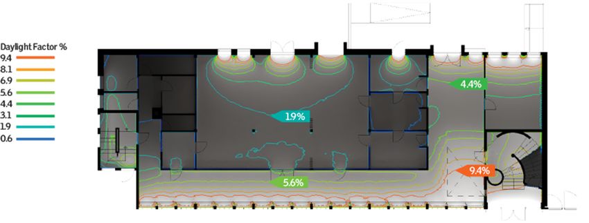
Heritage 2021, 4 2748
Heritage 2021, 4 FOR PEER REVIEWIn order to achieve this, high ambitions were necessary. Prior to the renovation, in addition 3
to focusing on the level of insulation, many detailed analyses of the daylight performance
of the building were also made.
The main purpose of this paper is to demonstrate that it is possible to reduce energy
the building acts as a culture centre. The renovation of the Osram Building was part of a
consumption and at the same time improve the indoor climate without compromising the
strategic cooperation with a number of Danish enterprises for the purpose of mutual
cultural values of buildings.
profiling on climate-friendly buildings and should therefore present a spearhead for
Both renovation projects achieved significant energy savings and consequently CO2 -
possibilities and methods of renovating old industrial and commercial buildings that are
emission reductions. The indoor climate in both buildings have also improved significantly;
worth preserving. In order to achieve this, high ambitions were necessary. Prior to the
for the Osram Building, natural ventilation provides fresh air and helps to avoid high indoor
renovation, in addition to focusing on the level of insulation, many detailed analyses of
temperatures, while new roof windows provide increased daylighting levels. In Ryesgade
the daylight performance of the building were also made.
30, the new windows and insulation of the façade have improved airtightness and thereby
The main purpose of this paper is to demonstrate that it is possible to reduce energy
removed draughts and risks of condensation, while the new mechanical ventilation system
consumption and at the same time improve the indoor climate without compromising the
provides fresh air.
cultural values of buildings.
Both renovation
2. Renovation projects achieved significant energy savings and consequently CO2-
Project Descriptions
emission
2.1. Ryesgadereductions.
30 The indoor climate in both buildings have also improved
significantly; for the Osram Building, natural ventilation provides fresh air and helps to
Ryesgade 30 is a very well-documented renovation case. It was part of a research-
avoid high by
project lead indoor temperatures,
the Technical while new
University roof windows
of Denmark, and theprovide increased
renovation wondaylighting
the 2013
levels. In Ryesgade 30, the new windows and insulation of
“RENOVER-prisen”, an award given to extraordinary renovation projects. For the façade have improved
these
airtightness
reasons, most andof thethereby removed
information givendraughts and has
in this paper risksalready
of condensation, while
been published the new
in papers,
mechanical
reports, ventilation
etc.; however, system
most of it provides
in Danishfresh air.
[12–14].
Ryesgade 30 is a multi-storey apartment building located in Copenhagen, Denmark.
It2.was
Renovation
built in 1896Project
and Descriptions
has six floors with 32 apartments divided in three different stair-
2.1. Ryesgade
wells (block A, 30B and C) and a total heated area of 2760 m2 . On the ground floor, the building
has commercial
Ryesgade premises.
30 is a very The building has anrenovation
well-documented unheated basement
case. It wasandpart
an unheated at-
of a research-
tic. Ryesgade
project 30 has
lead by the aTechnical
heritage value corresponding
University of Denmark, to Class
and the4 inrenovation
the SAVE classification
won the 2013
system [15], which means
“RENOVER-prisen”, an that
award thegiven
façadetoofextraordinary
the building cannot be changed
renovation (theFor
projects. period
these
masonry with horizontal cornices and bands are protected). Figure 1 shows
reasons, most of the information given in this paper has already been published in papers, the façade of
the building and Figure 2 shows a horizontal
reports, etc.; however, most of it in Danish [12–14]. cross section of the apartment layout.
Before the renovation,
Ryesgade the exterior
30 is a multi-storey walls were
apartment solidlocated
building brick masonry with a thickness
in Copenhagen, Denmark.
1
varying from 350–710 mm
It was built in 1896 and has (1 –3 bricks). Windows had one pane
2 six floors with 32 apartments divided in threeof glass in a wooden
different
frame, were(block
stairwells very A, energy-inefficient
B and C) and a totaland heated
gave riseareatoofcold
2760draughts
m2. On the in the apartments.
ground floor, the
The horizontal
building has division
commercialabove the basement
premises. was uninsulated
The building and the roof
has an unheated had 50and
basement mman
insulation. The building is heated by district heating and had natural
unheated attic. Ryesgade 30 has a heritage value corresponding to Class 4 in the SAVE ventilation through
leaks in the building
classification systemenvelope andmeans
[15], which opening ofthe
that thefaçade
windows. of the building cannot be changed
(the period masonry with horizontal cornices andpart
As mentioned, the Ryesgade 30 renovation was of a are
bands research project,Figure
protected). and therefore
1 shows
several different solutions were investigated regarding possible energy improvements.
the façade of the building and Figure 2 shows a horizontal cross section of the apartment
All pre-renovation measurements and tests are described in detail in [14].
layout.
Figure 1. Façade of Ryesgade 30 after renovation, including new roof and penthouse apartments.
Figure 1. Façade of Ryesgade 30 after renovation, including new roof and penthouse apartments.
Ground floor has commercial premises.
Ground floor has commercial premises.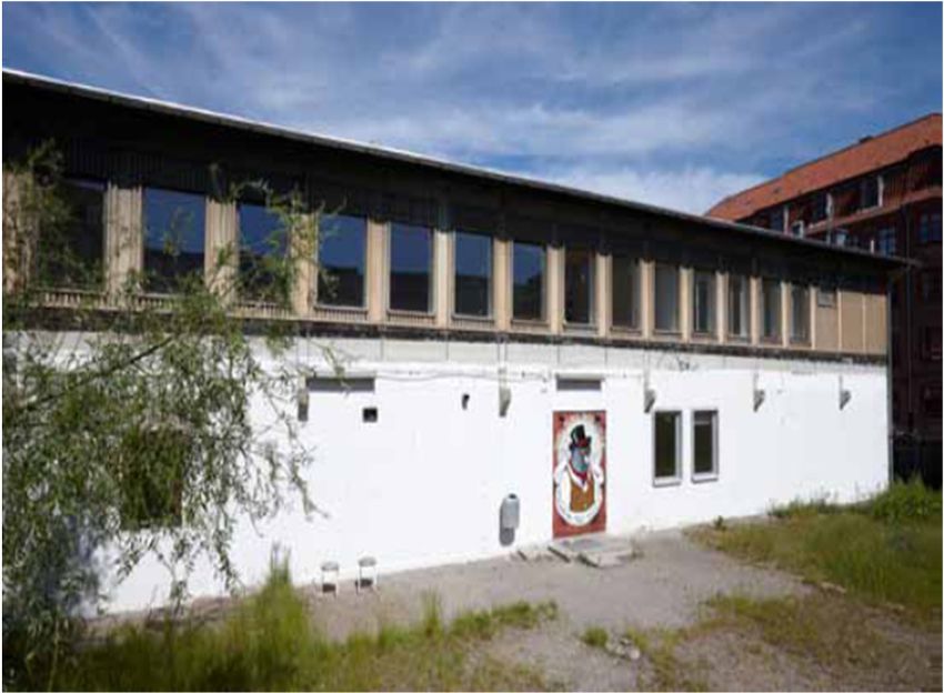
Heritage 2021, 4 2749
Heritage 2021, 4 FOR PEER REVIEW 4
Figure2.2.Horizontal
Figure Horizontalcross
crosssection
sectionshowing
showingthe
theapartment
apartmentlayout
layoutofofthe
thebuilding.
building.Blue
Blueisisstairwell
stairwellA,
A,
red is stairwell B and green is stairwell
red is stairwell B and green is stairwell C.C.
Before
For the the renovation,
façade, internal the exteriorwas
insulation walls wereinsolid
tested one brick masonry
apartment. with
This testainvolved
thickness
varying from
measuring 350–710 mm
temperature (1½–3 bricks).
and relative humidity Windows
behind thehadinsulation
one paneand of glass
at twoinbeam
a wooden
ends
frame,
and were very
measuring energy-inefficient
temperature and gave in
behind insulation rise to coldreveals.
window draughts in the
These apartments.
tests showed that The
horizontal
internal divisionwas
insulation above the basement
a viable solutionwasanduninsulated
suggested thatand40 the
mm roof had 50 mm
insulation insula-
could be
tion. The
added building
to the walls andis heated
20 mmbytodistrict heating
the reveals, andand had natural
therefore ventilation
this was chosen asthrough leaks
the solution
for building.envelope and opening of the windows.
in the building
For the windows,
As mentioned, thefour different
Ryesgade solutions were
30 renovation was tested:
part of three different
a research variations
project, and there-of
renovating
fore severalthe existingsolutions
different windowswere and one solution where
investigated windows
regarding possiblewere replaced
energy with
improve-
new replicas.
ments. The conclusion
All pre-renovation was that the and
measurements newtests
replicas had the best
are described energyinperformance
in detail [14].
while For
alsothe
being the cheapest
façade, internalsolution,
insulationand thetested
was Municipality
in one of Copenhagen
apartment. Thisapproved
test involvedthis
choice for the
measuring full renovation.
temperature and relative humidity behind the insulation and at two beam ends
and For the ventilation,
measuring temperaturedecentral
behindbalanced mechanical
insulation in window ventilation
reveals. with
Theseheat recovery
tests showedwas that
tested
internal insulation was a viable solution and suggested that 40 mm insulationHowever,
in one apartment. Unfortunately, the test gave no unequivocal answers. could be
all apartments
added wereand
to the walls fitted withtomechanical
20 mm the reveals,ventilation
and thereforewith heat
this was recovery,
chosen as butthedifferent
solution
systems were used in each stairwell: Stairwell A, traditional central system; Stairwell
for the building.
B, central
For thedemand
windows,controlled system; Stairwell
four different solutions C, decentral
were tested: system. This way
three different the threeof
variations
systems could be compared through detailed measurements.
renovating the existing windows and one solution where windows were replaced with
newFor the floor
replicas. Theover the basement,
conclusion was that100the
mm newinsulation
replicaswas
hadadded
the bestfrom beneath,
energy and for
performance
the part of the masonry wall acting as fire protection (gable), 200 mm
while also being the cheapest solution, and the Municipality of Copenhagen approved of mineral wool was
added to the outside. Finally,
this choice for the full renovation. photovoltaic panels were added to the roof. The photovoltaic
system Foris the
expected to produce
ventilation, 8950 balanced
decentral kWh per mechanical
year, more or less covering
ventilation with the
heat electricity
recovery
consumption of the new ventilation systems.
was tested in one apartment. Unfortunately, the test gave no unequivocal answers. How-
ever,Inall
addition to thewere
apartments energy improvements,
fitted a seriesventilation
with mechanical of general with
improvements were carried
heat recovery, but dif-
out during the renovation. New kitchens and bathrooms were installed, and all facades,
ferent systems were used in each stairwell: Stairwell A, traditional central system; Stair-
the basement and stairwells were renovated. All installations were replaced, except for
well B, central demand controlled system; Stairwell C, decentral system. This way the
parts of the heating system. Four new penthouse apartments with individual roof terraces
three systems could be compared through detailed measurements.
were added to the top of the building, which increased the heated floor area by 20% to
For the floor over the basement, 100 mm insulation was added from beneath, and for
3310 m2 and significantly increased the value of the building.
the part of the masonry wall acting as fire protection (gable), 200 mm of mineral wool was
The energy improvements of Ryesgade 30 are summed up in Table 1.
added to the outside. Finally, photovoltaic panels were added to the roof. The photovol-
taic system is expected to produce 8950 kWh per year, more or less covering the electricity
consumption of the new ventilation systems.
In addition to the energy improvements, a series of general improvements were car-
ried out during the renovation. New kitchens and bathrooms were installed, and all fa-
cades, the basement and stairwells were renovated. All installations were replaced, except
for parts of the heating system. Four new penthouse apartments with individual roof ter-
races were added to the top of the building, which increased the heated floor area by 20%
to 3310 m2 and significantly increased the value of the building.
The energy improvements of Ryesgade 30 are summed up in Table 1.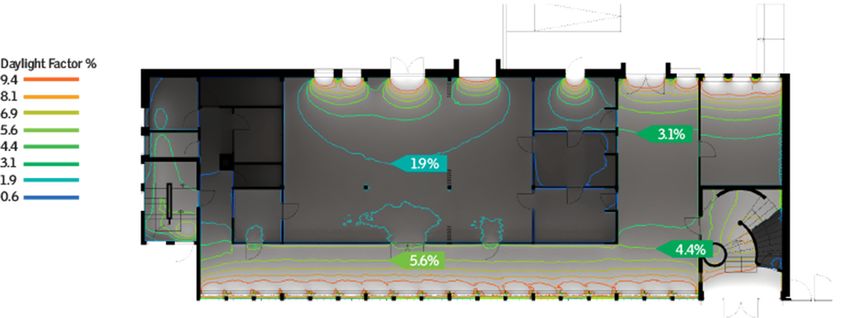
Heritage 2021, 4 2750
Heritage 2021, 4 FOR PEER REVIEW 5
Heritage 2021, 4 FOR PEER REVIEW 5
Table 1. Energy improvements in Ryesgade 30 [12]. Calculated values.
Table 1. Energy improvements in Ryesgade 30 [12]. Calculated values.
Table 1. Energy improvements in Ryesgade 30 [12]. Calculated values.2
U-Value
U-value(W/m
(W/m K)2K)
Construction Before U-value (W/m2K)After
Construction Before After
Construction
Brick
Brick wall
wall (mean)
(mean) Before
1.40 1.40 After
0.37 0.37
Brick wall (mean)
Windows
Windows 1.40
4.20 4.20 0.37
0.89 0.89
Floor over basement 1.50 0.30
Floor Windows
over basement 4.20
1.50 0.89
0.30
Roof
Floor over basement 1.50 0.52 0.30 0.15
Roof 0.52 0.15
System
Roof 0.52 0.15
System
System
Ventilation
Ventilation Natural
Natural Mechanical
Mechanical with recovery
with heat heat recovery
Photovoltaics None 80 m 2
Ventilation
Photovoltaics Natural
None Mechanical with
80 m2 heat recovery
Photovoltaics None 80 m2
2.2.
2.2.The
TheOsram
OsramBuilding
Building
2.2. The
The Osram Building was built in 1953 as an industrial building. It was the first prefab-
The OsramBuilding
Osram Building was built in 1953 as an industrial building. It was the first pre-
ricated house
The
fabricated in Copenhagen,
Osram
house Building wasbuilt
builtas
in Copenhagen, an office
inbuilt
1953 as an
as and warehouse
anindustrial
office for Nordisk
building.
and It wasGlødelampe
warehouse the first
for pre-
Nordisk
Industri A/S.
fabricated As
house partinof a Neighbourhood
Copenhagen, Development
built as an Project
office and in a former
warehouse
Glødelampe Industri A/S. As part of a Neighbourhood Development Project in a former semi-industrial
for Nordisk
area of Copenhagen,
Glødelampe Industri the CityAsofpart
Copenhagen initiated an energy renovation of thein cultural
semi-industrial area ofA/S.
Copenhagen, of the
a Neighbourhood
City of Copenhagen Development
initiated Project
an energy arenova-
former
centre “OSRAM”.
semi-industrial The
area facade
of of the
Copenhagen, building
the City is listed.
of The
Copenhagenbuilding was
initiated renovated
an energy in 2009
renova-
tion of the cultural centre “OSRAM”. The facade of the building is listed. The building
(see
tionFigures 3 and
of the cultural4).centre
was renovated in 2009 (see“OSRAM”.
Figures 3 and The4).facade of the building is listed. The building
was renovated in 2009 (see Figures 3 and 4).
Figure3.3.Façade
Figure Façadefacing
facingthe
themain
mainstreet
streetafter
afterrenovation.
renovation.
Figure 3. Façade facing the main street after renovation.
Figure 4. Façade facing inside after renovation. LEDs, off (left) and on (right).
Figure4.4.Façade
Figure Façadefacing
facinginside
insideafter
afterrenovation.
renovation.LEDs,
LEDs,off
off(left)
(left)and
andon
on(right).
(right).
The objectives of the renovation were:
Theobjectives
The objectivesofofthe
therenovation
renovationwere:
were:
• To energy renovate a former industrial building, now in use as a culture centre, by
•• To
To energy
energy
utilizing renovate
renovate
daylight aaformer
and former industrial
industrial
combining building,
building,
mechanical now
andnow ininuse
natural use asaaculture
as culture
ventilation centre,by
centre,
to improve by
the
utilizing
utilizing daylight and combining mechanical and natural ventilation to improve
daylight and combining mechanical and natural ventilation to improve the
indoor climate; the
indoorclimate;
indoor climate;
• To minimize energy consumption by improving the thermal envelope and utilizing
•• To
To minimize
minimize
energy
energy consumption
savingenergy consumptionby
lighting; byimproving
improvingthethethermal
thermalenvelope
envelopeand
andutilizing
utilizing
energy saving lighting;
energy saving lighting;
•• Tominimize
To minimizethe
the resources
resources required
required (and
(and thethe
COCO 2-emissions) during both construc-
2 -emissions) during both construction
• To
tionminimize
and the resources required (and the CO
upkeep. 2-emissions) during both construc-
and upkeep.
tion and upkeep.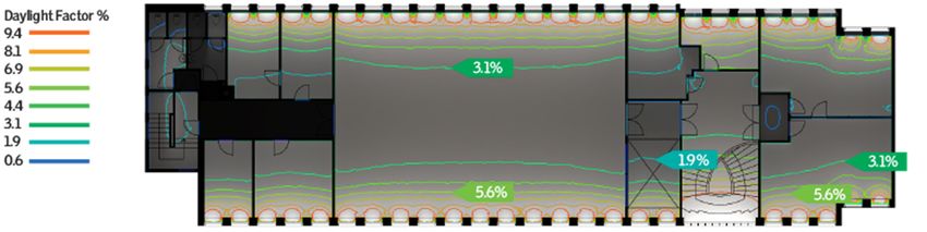
Windows 2.70–5.90 1.20
Doors 1.00–5.20 1.00–1.50
Slab floor and basement deck 0.57–2.37 0.57–2.37
Heritage 2021, 4 2751
The walls were a mix of prefabricated concrete elements, concrete columns and un-
insulated brick walls, and 380 mm insulation was added on the inside. The lower part of
the back façade was insulated on the outside (see Figures 5 and 6).
The windows
Table 2 showsinthe theU-values
building ranged fromafter
before and singlerenovation
glass windows
of thewith different
Osram levels
Building.
of sashthe
Before to standard windows
renovation, with
the roof two layers
insulation wasof glass. The main
performed withentrance
mineraldoor had a single
granules later
layer of glass. The
supplemented withtwo other
batts to aentrance doors toof
total thickness the building
150 mm. The werecentre
relatively
of the new.
roofAll
hadwin-
a
dows werewith
footbridge replaced by low
an extra energy
100 mm windows
insulation. Towith thin frames,
the deck except
above the for the
gate (to the right
façade
ofwin-
the
dows on the
entrance), 120ground floor. and
mm concrete Here, floor-to-ceiling
380 mm insulationglazing was added
was added on the on the inside to pre-
outside.
serve the expression of the façade. Skylights were installed in the roof.
Table 2. Osram
Before Building. U-values
renovation, before/after
half of the ground renovation.
floor was aCalculated values. facing the build-
deck construction
ing’s grounds. It consisted of 120 mm concrete on 120 mm cinder. The remaining part
U-Value (W/m2 K)
faced the partially heated basement and consisted of 200 mm reinforced concrete. No in-
sulationConstruction
was added to the slab/deck, butBefore 100 mm insulation was addedAfter to the outside of
the foundation Roofto reduce thermal bridge0.20–0.30
effects. 0.20–0.30
Deckoriginal
The above the gate system was based
heating 3.90
on district heating using a steam0.09 supply. The
Walls 1.65–3.73
heat distribution system was a single-pipe system. The new heating system is based on 0.09
Windows 2.70–5.90 1.20
district heating using a hot water supply. The heat distribution system is a two-pipe sys-
Doors 1.00–5.20 1.00–1.50
tem,
Slab and
floorthermostat
and basement valves
deck have been added to all radiators.
0.57–2.37 0.57–2.37
In addition to the existing windows, the renovated building has an added 24 m2 of
roof windows, 16 roof windows of 0.66 m x 1.40 m and 12 roof windows of 0.66 m x 1.18
m, toThe walls the
increase were a mix of
amount ofdaylighting
prefabricated concrete
in the elements,
building. concrete columns
In the stairwell, and
the horizontal
uninsulated brick walls, and 380 mm insulation was added on the inside.
division was removed to allow for the daylight from the roof windows to penetrate all theThe lower part
of theto
way back
the façade
groundwas insulated on the outside (see Figures 5 and 6).
floor.
Heritage 2021, 4 FOR PEER REVIEW 7
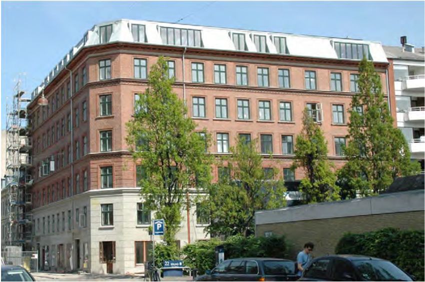
Figure 5. Façade facing the garden before renovation. The façade was originally the division between
Figure
the office5.area
Façade facingand
(existing) the the
garden before
factory area renovation.
(which was The
torn façade was originally
down many the
years ago). division
The façade be-
is
tween
not the office area (existing) and the factory area (which was torn down many years ago). The
protected.
façade is not protected.
Figure6.6.Façade
Figure Façadefacing
facingthe
thegarden
gardenafter
afterrenovation.
renovation.
The original ventilation system was a simple mechanical exhaust system where air
was removed from toilets and kitchens. In the renovated building, mechanical ventilation
with heat recovery was installed, and this was supplemented by natural ventilation via
the roof windows. The natural ventilation through the roof windows is controlled by elec-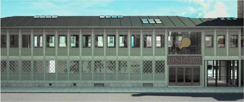
Heritage 2021, 4                                                                                           2752

                        The windows in the building ranged from single glass windows with different levels
                   of sash to standard windows with two layers of glass. The main entrance door had a
                   single layer of glass. The two other entrance doors to the building were relatively new.
                   All windows were replaced by low energy windows with thin frames, except for the façade
                   windows on the ground floor. Here, floor-to-ceiling glazing was added on the inside to
                   preserve the expression of the façade. Skylights were installed in the roof.
                        Before renovation, half of the ground floor was a deck construction facing the build-
                   ing’s grounds. It consisted of 120 mm concrete on 120 mm cinder. The remaining part faced
                   the partially heated basement and consisted of 200 mm reinforced concrete. No insulation
                   was added to the slab/deck, but 100 mm insulation was added to the outside of the
                   foundation to reduce thermal bridge effects.
                        The original heating system was based on district heating using a steam supply.
                   The heat distribution system was a single-pipe system. The new heating system is based
                   on district heating using a hot water supply. The heat distribution system is a two-pipe
                   system, and thermostat valves have been added to all radiators.
                        In addition to the existing windows, the renovated building has an added 24 m2 of roof
                   windows, 16 roof windows of 0.66 m × 1.40 m and 12 roof windows of 0.66 m × 1.18 m, to
                   increase the amount of daylighting in the building. In the stairwell, the horizontal division
                   was removed to allow for the daylight from the roof windows to penetrate all the way to
                   the ground floor.
                        The original ventilation system was a simple mechanical exhaust system where air
                   was removed from toilets and kitchens. In the renovated building, mechanical ventilation
                   with heat recovery was installed, and this was supplemented by natural ventilation via the
                   roof windows. The natural ventilation through the roof windows is controlled by electric
                   motors and is based on the indoor climate.
                        Solar heating was added to the building to supplement the district heating from the
                   hot water supply. Furthermore, decorative LED lighting has been added to the windowsills
                   in the original façade windows of the building, making it possible to set the scene for any
                   arrangement in the building as a cultural centre.

                   3. Calculated and Measured Energy Savings
                   3.1. Ryesgade 30
                        The data given in the following was taken from [13].
                        For Ryesgade 30, the heat consumption before the renovation was measured as
                   155.5 kWh/m2 per year (average for 2007–2009). This was compared to the results of
                   an IDA ICE [16] simulation model, which predicted the consumption as 151.6 kWh/m2
                   per year based on an indoor temperature of 20 ◦ C.
                        After the renovation, the consumption was measured as 83.0 kWh/m2 (September 2013
                   to September 2014), and during the same period the photovoltaic system produced approx.
                   11,000 kWh, corresponding to 3.3 kWh/m2 per year. The electricity production was approx.
                   20% higher than expected. The IDA ICE model had predicted a heat consumption of
                   60.6 kWh/m2 per year, so the actual consumption was significantly higher than expected.
                   Figure 7 shows the results of measurements and calculations.
                        One of the main reasons for not achieving the expected savings in heat consumption
                   was the fact that the indoor temperature after the renovation was significantly higher than
                   what is usually used in these types of calculations. The temperature was measured during
                   the heating season of 2013–2014 in blocks A and B (20 different sensors in total), and the
                   result showed an average indoor temperature of 22.5 ◦ C.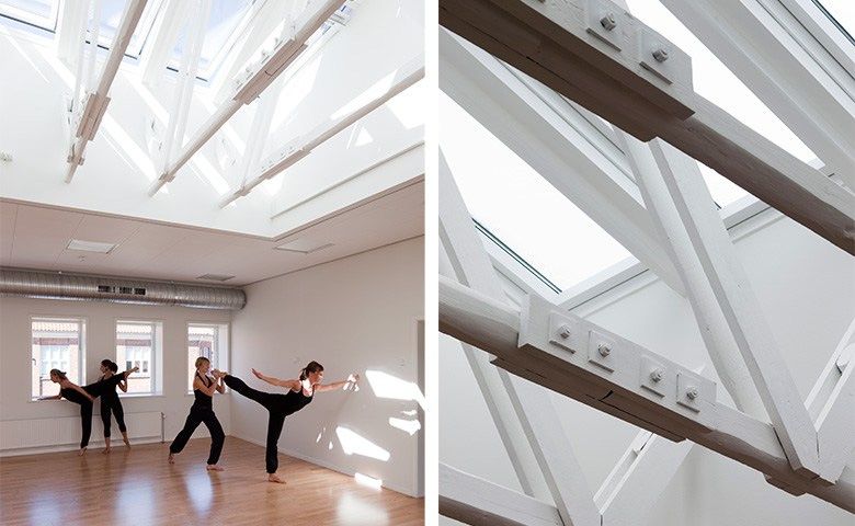
Heritage 2021, 4 2753
Heritage 2021, 4 FOR PEER REVIEW 8
Figure 7. Measured and calculated heat consumption before and after renovation of Ryesgade 30.
Figure 7. Measured and calculated heat consumption before and after renovation of Ryesgade 30.
IfOne of the
the IDA ICEmain reasons for
calculation not is
model achieving
revised to the expected
take savings
the actual indoor in heat consumption
temperature into
was the the
account, factexpected
that the indoor temperatureincreases
heat consumption after the renovation
from 60.6 towas 77.3significantly
kWh/m per 2 higher
year. than
what is usually
Another used inexplanation
possible these types for of calculations.
the difference The temperature
between was measured
measured and calculatedduring
the heating
heat consumption seasonisofthe 2013–2014
infiltration in blocks A and B (20
and ventilation different
of the sensors
building. In the in total), and the
calculations,
itresult showed an
was assumed average
that the heat indoor temperature
recovery rate wasof85% 22.5in°C.
average and that the infiltration
If the IDA ICE calculation 2
model is
was very low, i.e., 0.05 L/s per m . Parametric calculations revised to take the actual
with indoor temperature
the calculation modelinto
account,
show that,the expected heat
in particular, consumption increases
an underestimation from 60.6 to
of the infiltration 77.3
rate cankWh/m
influence 2 perthe
year.
heat
Another and
consumption, possible
because explanation
the opening for ofthewindows
difference andbetween
doors is measured
part of the and calculated
infiltration,
heat
this consumption
parameter is thedependent
is heavily infiltrationon anduserventilation
behaviour. of the building. In the calculations, it
wasUnfortunately,
assumed that the forheat recovery
Ryesgade 30,rate
nowas 85% ineconomic
detailed average and datathat
is the infiltration
readily was
available.
However,
very low,ini.e., a test apartment,
0.05 l/s per mapproximate
2. Parametric prices were calculated
calculations with the as: windowsmodel
calculation EUR 4665
show
(one
that,3-pane, three 2-pane
in particular, and two 1-pane),ofventilation
an underestimation system
the infiltration EUR
rate can5900, internal
influence theinsulation
heat con-
EUR 6660 (approx.
sumption, 25 m2the
and because total), consultancy,
opening of windows labour,andetc., EURis5240,
doors part ofi.e.,the
totalling approx.
infiltration, this
EUR 22,465 per
parameter apartment.
is heavily This does
dependent not cover
on user the cost of external insulation of the gable,
behaviour.
the new penthouse apartments
Unfortunately, for Ryesgade and30,
photovoltaics.
no detailed economic data is readily available. How-
ever, in a test apartment, approximate prices were calculated as: windows EUR 4665 (one
3.2. The Osram
3-pane, three Building
2-pane and two 1-pane), ventilation system EUR 5900, internal insulation
The
EUR 6660 primary
(approx. energy
25 m2use (including
total), consultancy, the primary energy
labour, etc., EURfactors) was
5240, i.e., calculated
totalling as
approx.
288 kWh/m 2 perapartment.
year before renovation and 153 2
EUR 22,465 per This does not cover the kWh/m per year
cost of external after, i.e.,
insulation a total
of the gable,
reduction of 47%. Theapartments
the new penthouse electricity consumption
and photovoltaics. before renovation was 45 kWh/m2 per year,
and after renovation it was 40 kWh/m2 per year. The heating consumption decreased from
158 2 per year, and the domestic hot water from 18 to 16 kWh/m2 per year.
3.2.toThe
37 Osram
kWh/m Building
The energy savings for the building is 9500 and 181,000 kWh per year for electricity
The primary energy use (including the primary energy factors) was calculated as 288
and heating, respectively. The savings from the façade insulation and the windows account
kWh/m2 per year before renovation and 153 kWh/m2 per year after, i.e., a total reduction
for 150,000 kWh per year, and the rest are from the heating and lighting systems, the
of 47%. The electricity consumption before renovation was 45 kWh/m2 per year, and after
controls and the solar panels (see Figure 8).
renovation it was 40 kWh/m2 per year. The heating consumption decreased from 158 to
The Osram Building was renovated in 2009, so the prices, etc., are from this time
37 kWh/m2 per year, and the domestic hot water from 18 to 16 kWh/m2 per year.
period. The total investment for the renovation project was approximately EUR 564,000, of
The energy savings for the building is 9500 and 181,000 kWh per year for electricity
which EUR 212,000 was directly aimed at energy reductions. The expected total savings
and heating, respectively. The savings from the façade insulation and the windows ac-
per year were EUR 13,000, i.e., resulting in a simple payback time for the entire project of
count for 150,000 kWh per year, and the rest are from the heating and lighting systems,
approximately 18 years. Energy savings should result in CO2 -reductions of approximately
the controls and the solar panels (see Figure 8).
29 tons per year for the entire renovation.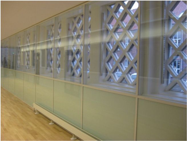
Heritage 2021, 4 2754
Heritage 2021, 4 FOR PEER REVIEW 9
Figure 8. Energy savings in percent divided into the different parts of the renovation.
Figure 8. Energy savings in percent divided into the different parts of the renovation.
The Osram
4. Detailed Building was renovated in 2009, so the prices, etc., are from this time
Analysis
period. The total investment
Both renovation for the renovation
projects involved projectofwas
a deeper analysis approximately
individual renovationEUR 564,000,
solutions,
of which EUR 212,000 was directly aimed at energy reductions. The expected
including their impact on, e.g., energy efficiency, indoor climate, moisture safety total savings
and
the overall economy of the projects. Thereby, these detailed investigations made by theof
per year were EUR 13,000, i.e., resulting in a simple payback time for the entire project
approximately
consultants 18 years.
helped Energy and
to determine savings should
select result
the best in CO2for
solutions -reductions of approximately
the projects.
29 tons per year for the entire renovation.
4.1. Ryesgade 30—Ventilation Systems and Window Solutions
4. Detailed
RyesgadeAnalysis
30 was part of a research project which facilitated the use of very detailed
Both renovation
investigations of a wideprojects
range ofinvolved
renovation a deeper
measures, analysis of individual
including, renovation
e.g., detailed solu-
in-situ mea-
surements on the performance
tions, including their impact on, of different solutions
e.g., energy for theindoor
efficiency, internal insulation
climate, of exterior
moisture safety
walls.
and the The following
overall describes
economy of thethe solutions
projects. that were
Thereby, these considered and tested regarding
detailed investigations made by
the
theventilation
consultantssystems
helped to and window and
determine solutions for best
select the Ryesgade 30. for
solutions Before the renovation,
the projects.
Ryesgade 30 had natural ventilation (through leaks in the building envelope and open
windows).
4.1. Ryesgade Three different solutions
30—Ventilation Systemswere installedSolutions
and Window in the building, as explained below.
InRyesgade
stairwell30 A,was
a traditional central mechanical
part of a research project which ventilation
facilitatedsystem
the useisoflocated in the
very detailed
basement. The system has a fresh air intake at the basement
investigations of a wide range of renovation measures, including, e.g., detailed in-situ level by the stairwell.
Existing chimneys
measurements on are
the used to carry of
performance airdifferent
exhaustsolutions
ducts from for bathrooms
the internaland kitchens
insulation of to
ex-
the basement. In addition, existing chimneys are used for the return
terior walls. The following describes the solutions that were considered and tested regard- of used air over the
roof.
ing theFresh air is fed
ventilation to apartments
systems and window via new ducts.
solutions forThe supplied
Ryesgade air to the
30. Before the remaining
renovation,
rooms has a constant air flow of 140 m3 /h. Exhaust air from the bathrooms is constant
Ryesgade 30 had natural ventilation (through leaks in the building envelope and open
at 20 m3 /h when the relative humidity is below 55%, and 54 m3 /h when it exceeds 55%.
windows). Three different solutions were installed in the building, as explained below.
In the kitchen, the exhaust is generally at 72 m3 /h, but rises to 144 m3 /h when the cooker
In stairwell A, a traditional central mechanical ventilation system is located in the
hood is activated.
basement. The system has a fresh air intake at the basement level by the stairwell. Existing
In stairwell B, the central ventilation system unit is located in the basement. The system
chimneys are used to carry air exhaust ducts from bathrooms and kitchens to the base-
has a fresh air intake at the basement level by the stairwell. There are new main channels
ment. In addition, existing chimneys are used for the return of used air over the roof. Fresh
for both fresh air and extraction from apartments. Existing chimneys are used for the return
air is fed to apartments via new ducts. The supplied air to the remaining rooms has a
of used air over the roof. The use of existing chimneys for the return of used air over the
constant air flow of 140 m3/h. Exhaust air from the bathrooms is constant at 20 m3/h when
roof has proven problematic in stairway B. Although the chimney is sealed very thoroughly
the relative humidity is below 55%, and 54 m3/h when it exceeds 55%. In the kitchen, the
in connection with the renovation, one apartment experienced minor odour nuisances due
exhaust is generally at 72 m3/h, but rises to 144 m3/h when the cooker hood is activated.
to leakage of exhaust air. This clearly shows that the use of existing chimneys for the return
of air In
canstairwell
be risky.B,The
the ventilation
central ventilation
systemsystem unit is located inbased
is demand-controlled the basement. The sys-
on CO2 , relative
tem has a fresh air intake at the basement level by the stairwell. There
humidity and temperature. In addition, there is a user panel to regulate specific user needs. are new main chan-
nels for both fresh air and extraction from apartments. Existing
When no one is present in the apartment, the municipality has granted dispensation to chimneys are used for the
return of used air over the roof. The use of existing chimneys for
deviate from the requirements in the building regulations, making it possible to reduce the the return of used air
over the roof has
air change to 22 m3 /h. proven problematic in stairway B. Although the chimney is sealed very
thoroughly
In stairwellin connection with thesystems
C, the ventilation renovation, one apartment
are decentral systems experienced minor level.
at the apartment odour
nuisances due to leakage of exhaust air. This clearly shows that
This means that each apartment has its own unit. The systems are wall-hung and placed the use of existing chim-
neys for the return of air can be risky. The ventilation system is
in cupboards in the kitchen. Each system has a fresh air intake via the facade. On one demand-controlled based
on CO2, relative humidity and temperature. In addition, there is a user panel to regulate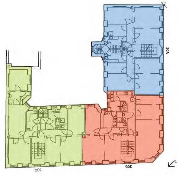
Heritage 2021, 4                                                                                              2755

                   side of the building, returns are managed over the roof and, on the other side, returns go
                   through the end wall. The ventilation systems do not need management (user intervention
                   to control extraction levels); however, the system can be forced to maximum capacity by
                   activating the cooker hood. The plant has a capacity limited of approx. 180 m3 /h.
                        Extensive user surveys have been conducted to get feedback on the ventilation systems
                   in the three stairwells. Overall, the residents are satisfied with the ventilation in Ryesgade
                   30; however, there are still problems that need to be addressed, which are, primarily:
                   •     Ventilation noise (valves and unit noise);
                   •     The cooker hood works poorly;
                   •     Residents do not understand how the ventilation (and the system) works.
                         Regarding operational reliability, the decentralized facilities in stairwell C have proven
                   to be clearly better than the central systems in stairwells A and B. The decentralized systems
                   have also proven to be significantly easier to troubleshoot, because a given error is only
                   related to a single apartment and unit, and service work will only affect a single lease at
                   a time.
                         The electricity consumption of the three different ventilation systems has been mea-
                   sured from August 2013 to the end of August 2014. However, the systems have not had a
                   stable operation throughout the period, but since January 2014, the operation seems to be
                   relatively stable. Based on the measurements, the expected annual electricity consumption
                   can be determined as shown in Table 3.

                   Table 3. Annual electricity consumption for mechanical ventilation systems.

                                                               Stairwell A        Stairwell B      Stairwell C
                       Electricity consumption   (kWh/m2 )         9.9                2.4              2.3

                         As can be seen, there is a large electricity consumption for ventilation in stairwell A,
                   which is partially due to the fact that the heat recovery units are located in the basement
                   and return happens over the roof. This results in large pressure losses, as the air has to
                   travel a long way. In stairwell B, the air must travel the same distance, but in the demand-
                   controlled ventilation, the air volume is significantly lower and the electricity consumption
                   is therefore also lower than in the plant with constant air flow.
                         Regarding the windows, four different solutions were tested. The windows were
                   ready for replacement, but the municipality wanted to preserve the windows for reasons
                   of principle. The solution with a coupled frame, however, met resistance from tenants who
                   did not want windows that opened inward because the solution is cumbersome and limits
                   the use of the windowsill. Furthermore, this solution also proved problematic because the
                   existing window frames had significant moisture damage.
                         The first solution was a 1 + 1 + 1 solution, which includes an extra layer of glass fitted
                   on the outside of the existing window so that there is one plain of glass and two individual
                   energy glasses. The distance between the two individual energy glasses in the test window
                   was 23 mm. This should be at least 20 mm, because smaller cavities significantly reduces
                   the insulating ability.
                         The second solution was a 1 + 1 solution, i.e., corresponding to a refurbishment of
                   the existing solution, with installation of an extension energy glass on the inside in a
                   separate frame.
                         The third solution was a 1 + 1 solution, where 4 mm tempered glass was mounted
                   directly on the inside of the window frame using patented special hinges and fittings.
                   The advantage of this special solution is that the air tightness does not depend on the
                   behaviour of the residents and that the windowsill does not need to be cleared when
                   opening the window.
                         The fourth solution was a complete replacement of the window with a replica of the
                   original. This was a 1 + 2 solution with two energy glasses (inner and outer panes) and
                   energy panes with “warm” pane edge and krypton filling.
Heritage 2021, 4 2756
Table 4 shows the energy data for the various window solutions. The overall energy
efficiency is expressed as the energy balance, Eref , for the windows, i.e., the solar heat gains
minus the heat loss over a heating season (based on Danish weather data). Eref is a relevant
term to compare the performance of different windows during the heating season and is
based on reference dimensions of 1.23 × 1.48 m.
Table 4. Energy data for the investigated window solutions.
# Window Solution U (W/m2 K) g [-] Eref (kWh/m2 per Year) LT (-)
1 1 + 1 + 1 secondary glazing (refurb.) 1.08 0.37 −26 0.37
2 1 + 1 secondary glazing (refurb.) 1.62 0.44 −58 0.45
3 1 + 1 coupled frame (refurb.) 1.76 0.44 −73 0.45
4 1 + 2 coupled frame (new) 1.13 0.29 −45 0.39
The prices for the different solutions were also compared and are specified in Table 5.
Table 5. Cost for different window solutions in EUR (2013 prices).
# Description Price Total 2-Pane window Total 3-Pane Window
Repair and paint 467
1
Secondary glazing 2 layers 1163 1630
Repair and paint 467
2
Secondary glazing 1 layer 1100 1567
Repair and paint 467
3
Coupled frame 1 + 1 1679 2146
New window 2 + 1 1193
4
Installation 380 1573
Comparing the window solutions in Table 4, it is clear that solutions 1 and 4 perform
best regarding energy efficiency. The U-values are quite low and, due to the three layers of
glass in both solutions, the g-value is also quite low. Light transmittances are similar for all
solutions. The energy balance (Eref ) is negative in general, which means that transmission
losses outweigh solar gains. From Table 5, it is evident that solution 4 is the cheapest.
Please note that for solution 4 the prices are for a 3-pane window as opposed to the other
solutions that are for 2-pane windows, i.e., the price for solution 4 is valid for a window
that is approximately 50% larger than the others.
Based on this information, it was concluded that solution 4 was the cheapest, while at
the same time being highly energy efficient. The solution was also very user friendly, i.e.,
all the glass was fitted in one frame, and they had been manufactured to replicate, from
the outside, the originals. Project participants presented these findings to the municipality
Heritage 2021, 4 FOR PEER REVIEW who gave permission to replace the windows of the building. The new windows 12 are shown
in Figure 9.
(a) (b)
Figure 9. New windows from the inside (left) and from the outside (right). Source: Leif Rönby.
Figure 9. New windows from the inside (left) and from the outside (right). Source: Leif Rönby.
4.2. The Osram Building—Daylighting Technologies
In connection with the renovation, a new and more appropriate layout of the ground
floor was considered. There are two main entrances; the new one from the courtyard in-
cludes a gate in the access/escape route. In the large entrance hall, penetration of the ceil-(a) (b)
Heritage 2021, 4 Figure 9. New windows from the inside (left) and from the outside (right). Source: Leif Rönby.
2757
4.2. The Osram Building—Daylighting Technologies
In connection
4.2. with the renovation,
The Osram Building—Daylighting a new and more appropriate layout of the ground
Technologies
floor was considered. There are two main entrances; the new one from the courtyard in-
In connection with the renovation, a new and more appropriate layout of the ground
cludes
floora gate in the access/escape
was considered. There areroute.
two mainIn the large entrance
entrances; the newhall,
one penetration of the ceil-
from the courtyard
ing includes
creates double
a gate in the access/escape route. In the large entrance hall, penetration a
room height in part of the room. From the entrance hall, of passage
the
along the creates
ceiling street facade givesheight
double room accessinto two
part large
of the flexFrom
room. roomsthe and three
entrance smaller
hall, activity
a passage
rooms.
along The
the large roomsgives
street facade openaccess
towards
to twothe garden,
large andand
flex rooms thethree
activity rooms
smaller have
activity glazing
rooms.
The large rooms open towards the garden, and the activity rooms have glazing
placed high in the walls, allowing “used” daylight to enter, while prohibiting seeing in placed high
frominthe
the other
walls, rooms.
allowingLavatories
“used” daylight
and atobathroom
enter, whileareprohibiting
located inseeing in fromcorner.
the eastern the otherIn the
rooms. Lavatories and a bathroom are located in the eastern corner. In the southern corner,
southern corner, there is an office facing the garden and new window slits to the gateway
there is an office facing the garden and new window slits to the gateway (see Figure 10).
(see Figure 10).
Figure 10. Ground floor layout.
Figure 10. Ground floor layout.
ThisThis
layout of of
layout thethe
building
buildingpresents
presents several advantages.
several advantages. The
The passage
passage along
along the facade
the facade
is a is
partly heated
a partly heatedroom,
room,which
whichwill
willreduce theheat
reduce the heatloss
lossthrough
throughthethe facade.
facade. As this
As this facade
facade
symbolizes
symbolizes thethe house
house architectonically, it
architectonically, it would
wouldbe behard
hardtotoinsulate it without
insulate damaging
it without damaging
the the present
present expression.ByByreplacing
expression. replacing insulation
insulation with
withaaroom-high
room-high double
doublewallwall
of energy
of energy
efficient glass, the architectonic expression will be maintained and the heat loss reduced,
efficient glass, the architectonic expression will be maintained and the heat loss reduced,
though somewhat less than by traditional, external insulation.
though somewhat less than by traditional, external insulation.
On the first floor, the present layout is maintained, apart from the area around the
front stairs where it is now possible to look towards and communicate with the entrance
hall and the passage downstairs.
On the first floor, there is access to the great hall and the three offices making up
the primary rooms on this floor. Roof windows are installed above the great hall, the
offices and the hallway and are fitted with electrically-operated sun screening and opening
devices for natural ventilation (see Figure 11).On the first floor, the present layout is maintained, apart from the area around the
front stairs where it is now possible to look towards and communicate with the entrance
hall and the passage downstairs.
On the first floor, there is access to the great hall and the three offices making up the
Heritage 2021, 4 primary rooms on this floor. Roof windows are installed above the great hall, the offices 2758
and the hallway and are fitted with electrically-operated sun screening and opening de-
vices for natural ventilation (see Figure 11).
Figure 11. First floor layout.
Figure 11. First floor layout.
The roof windows in the hallway will contribute significantly to creating a lighter
The roof windows in the hallway will contribute significantly to creating a lighter
and more inviting entrance area and to make the passage more open. The windows in the
and more inviting entrance area and to make the passage more open. The windows in the
great
great hall
hall are
are relatively small, but
relatively small, but the
the roof windows will
roof windows will improve
improve the
the daylight
daylight conditions
conditions
considerably in this area. At the same time, the roof windows will contribute
considerably in this area. At the same time, the roof windows will contribute actively actively to
to
adjusting the indoor climate when a large amount of people are gathered
adjusting the indoor climate when a large amount of people are gathered for activities suchfor activities
such
as folkasdancing,
folk dancing, lectures
lectures or private
or private parties.
parties.
The
The daylighting performance of the Osram
daylighting performance of the Osram Building
Building has been specified
has been specified using
using the
the
daylight
daylight factor
factor (DF)
(DF) asas aa performance
performance indicator.
indicator. The calculations of
The calculations the daylight
of the daylight given
given
below were performed by Velux [17]. Please note that there are slight differences
below were performed by Velux [17]. Please note that there are slight differences between between
the drawings used
the drawings usedin inthe
thedaylight
daylightcalculations
calculations (Figures
(Figures 12 12–13)
and 13)and
andthe
thedrawings
drawings of the
of the
first-floor layout in Figure 11. The daylight calculations were performed at an
Heritage 2021, 4 FOR PEER REVIEW first-floor layout in Figure 11. The daylight calculations were performed at an early stage early stage
14
Heritage 2021, 4 FOR PEER REVIEWof
of the
the design
design phase.
phase. 14
The daylight factor is a common and easy to use measure for the available amount of
daylight in a room. It expresses the percentage of daylight available in the interiors, on a
work plane, compared to the amount of daylight available at the exterior of the building
under known overcast sky conditions. The higher the DF, the more daylight is available
in the room. Rooms with an average DF of 2% or more are considered daylit. A room will
appear strongly daylit when the average DF is above 5%.
The daylight factor analysis has been performed using computer simulations of Ra-
diance. Figures 12–15 show the daylight factor levels obtained on each floor for two dif-
ferent variants evaluating the impact of the installed roof windows on the finalized de-
sign.
Figure 12.
Figure 12. First
First floor with roof
floor with roof windows.
windows.
Figure 12. First floor with roof windows.
Figure 13. First floor without roof windows.
Figure13.
Figure 13.First
Firstfloor
floorwithout
withoutroof
roofwindows.
windows.You can also read