Configuration Manager 7.40 - en User manual
←
→
Page content transcription
If your browser does not render page correctly, please read the page content below

Configuration Manager 7.40

en   User manual
Configuration Manager 7.40                                                 Table of contents | en   3

Table of contents
1                        Introduction                                                                5
1.1                      About this manual                                                           5
1.2                      Conventions in this document                                                5
1.3                      Additional documentation                                                    5
2                        System overview                                                             6
2.1                      Functions                                                                   6
3                        Installation and starting                                                   7
3.1                      System requirements                                                         7
3.2                      Installation                                                                7
3.3                      Starting the program                                                        7
3.4                      Uninstalling the program                                                    7
4                        User interface                                                              9
4.1                      Overview                                                                    9
4.2                      Main navigation bar tabs                                                   10
4.2.1                    The Remote Portal tab                                                      10
4.2.2                    The Network Scan tab                                                       11
4.2.3                    The My Devices tab                                                         11
4.2.4                    The Preferences tab                                                        11
4.3                      The Menu bar                                                               15
4.3.1                    The File menu                                                              15
4.3.2                    The Tools menu                                                             15
4.3.3                    The Help menu                                                              16
4.4                      Reload / Save icons                                                        17
4.5                      Toolbar icons                                                              17
4.6                      The Info bar                                                               18
4.7                      The Quick indication icons                                                 18
4.8                      The Status bar                                                             18
4.9                      The View pane                                                              19
4.10                     Used icons                                                                 19
4.11                     Shortcut menu                                                              21
4.12                     Blocked input fields                                                       23
5                        Working with Configuration Manager                                         25
5.1                      Adding devices to the system                                               25
5.1.1                    Adding devices (for example, cameras, encoders)                            25
5.1.2                    Adding iSCSI devices                                                       25
5.2                      Allocating devices                                                         25
5.2.1                    Allocating listed devices                                                  26
5.2.2                    Allocating unlisted devices                                                26
5.3                      Clearing device allocations                                                27
5.4                      Creating groups                                                            27
5.5                      Defining a group as site                                                   28
5.6                      Accessing the device                                                       28
5.7                      Replacing devices                                                          29
5.8                      Defining storage locations                                                 30
5.9                      System emulation                                                           30
5.10                     Notes on multiple configuration                                            31
5.11                     Configuring the toolbar section                                            31
5.12                     Getting device information                                                 32

Bosch Security Systems B.V.                                User manual               2021.04 | V8 | DOC
4      en | Table of contents                                                                    Configuration Manager 7.40

5.13                     Disabling network scan                                                                          32
5.14                     Using the Table view                                                                            32
5.15                     Importing .csv files                                                                            35
5.16                     Using Device Health Monitor                                                                     36
5.17                     Device configuration using the View pane                                                        37
5.18                     Managing certificates using MicroCA                                                             37
5.18.1                   Background information                                                                          37
5.18.2                   Initializing the MicroCA                                                                        38
5.18.3                   Configuring MicroCA using Smart Token                                                           38
5.18.4                   Configuring MicroCA using USB file                                                              40
5.18.5                   Signing device certificates                                                                     42
5.18.6                   Managing user token                                                                             45
5.18.7                   Creating user token                                                                             46
5.18.8                   Configuring token-based device authentication                                                   47
5.19                     Finding/editing DSA E-Series devices                                                            47
5.19.1                   Finding DSA E-Series devices                                                                    47
5.19.2                   Editing the port settings                                                                       47
5.19.3                   Changing the password                                                                           47
5.19.4                   Renaming the device                                                                             47
5.20                     Connecting to the Bosch Remote Portal                                                           48
5.20.1                   Requesting access the Bosch Remote Portal application                                           48
5.20.2                   Signing in to the Bosch Remote Portal application                                               48
5.20.3                   Adding cameras to the Bosch Remote Portal application                                           48
5.21                     App management for INTEOX cameras                                                               48
5.21.1                   Requesting access to the Security and Safety Things application store                           48
5.21.2                   Signing in to the Security and Safety Things application store                                  49
5.21.3                   Checking the app status of the cameras                                                          49
5.21.4                   Downloading apps for installation in a local network                                            49
5.21.5                   Installing downloaded apps locally and offline                                                  50
5.22                     Working with other components                                                                   50
5.22.1                   Video Content Analysis                                                                          50
5.22.2                   Monitor Wall                                                                                    51
                         Index                                                                                           52

2021.04 | V8 | DOC                                       User manual                              Bosch Security Systems B.V.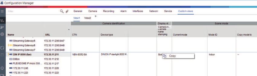
Configuration Manager 7.40                                                                           Introduction | en   5

1                        Introduction
1.1                      About this manual
                         This manual is intended for persons responsible for configuring and managing a CCTV system.
                         This manual describes how to configure the program.
                         This document assumes that the reader is familiar with both the CCTV system and the other
                         programs that are integrated into the system.

1.2                      Conventions in this document
                         The symbols and notations that follow are used to draw attention to special situations:

                         Notice!

      i                  This symbol indicates special features and provides tips and information for easier, more
                         convenient use of the software.

                         Terms that you can find in the program, such as menu options, commands or text in the user
                         interface, are written in bold.

1.3                      Additional documentation
                         After the program has been installed, this document is also available as Help within the
                         program.
                         More information
                         For more information, software downloads, and documentation, go to
                         www.boschsecurity.com and the corresponding product page.

Bosch Security Systems B.V.                                User manual                                    2021.04 | V8 | DOC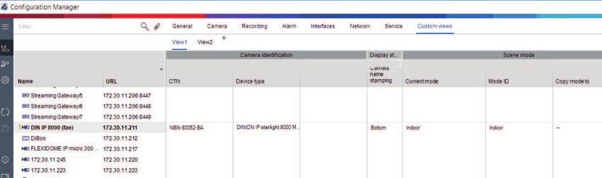
6     en | System overview                                                                      Configuration Manager 7.40

2                      System overview
                       The Configuration Manager program is used to configure all IP devices and components in
                       your CCTV network. With Configuration Manager you have access to all devices and software
                       components.

2.1                    Functions
                       Configuration Manager provides the following functions (the availability of these depends on
                       the environment in which the program is used):
                       –     Network Scan
                             The network scan is performed automatically every time Configuration Manager starts,
                             and is repeated at regular intervals.
                             This function automatically detects all compatible devices present in a network, such as
                             cameras or video senders, video receivers or VRM. The status of a device is also queried
                             in each scan and then indicated by the icons in front of the devices.
                       –     Device information and configuration
                             Comparable with the Web browser view, Configuration Manager shows the current
                             configuration for each device and allows you to change the settings.
                       –     Device system integration
                             You use the Device allocator in Configuration Manager to make devices accessible for use
                             with Video Client.
                       –     MicroCA
                             The MicroCA functionality in the Configuration Manager program is an easy-to-use tiny
                             certificate authority (CA) that facilitates the management of small to medium systems.
                       –     Multiple configuration
                             You can use Configuration Manager to make individual settings for multiple devices
                             simultaneously (for example, time settings), allowing you to configure large systems more
                             quickly.
                       –     Simpler access to devices
                             The Screenshot Scan function gives an overview of all the cameras that provide video
                             data. The screenshots can be used to identify the camera and device, and give you direct
                             access to said camera or device.
                       –     Table View
                             This allows you to compile specific parameter settings for selected devices. This provides
                             you with a quick overview of the settings that are of interest to you and allows you to
                             export this information for archiving at the push of a button.
                       –     Device Health Monitor
                             This provides you with a quick overview of the status of selected devices, such as the
                             encoder load and type of network connection.
                       –     System emulation
                             The complete system configuration can be saved as a system image and emulated using a
                             different Configuration Manager application. This function helps you to isolate problems
                             without having to access the actual system.
                       –     Access to license management
                             Firmware modules requiring a license, such as IVA (Intelligent Video Analysis), are set up
                             using Configuration Manager.

2021.04 | V8 | DOC                                       User manual                                 Bosch Security Systems B.V.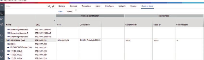
Configuration Manager 7.40                                                                     Installation and starting | en   7

3                        Installation and starting
                         The Configuration Manager program is automatically part of the installation for all video IP
                         devices that require the Configuration Manager program for configuration purposes.
                         Furthermore, you can also use the Configuration Manager program to simplify the
                         configuration in a CCTV system with many similar video senders.

3.1                      System requirements
                         Notice!

      i                  All Microsoft updates and hotfixes must be installed on target PCs. Graphic card drivers must
                         also have the latest officially released version described in the VideoSDK help.

3.2                      Installation
                         You can install Configuration Manager on as many computers running Microsoft Windows as
                         you wish.

                         Notice!

      i                  Using multiple Configuration Manager programs in the network, maintaining the same or an
                         overlapping set of devices simultaneously can result in unpredictable effects when writing to
                         the devices.

                         To install Configuration Manager:
                         1.   Download the software package.
                         2.   Close all other applications before starting the installation.
                         3.   Select the extraction directory, then double-click Setup_ConfigManager.exe.
                              The Configuration Manager wizard dialog box appears.
                         4.   On the Welcome dialog box, click Next.
                         5.   Follow the instructions on the screen.
                              Note: We recommend using the default destination folder.
                         6.   Click Finish.

3.3                      Starting the program
                         After successful installation, you will find the Configuration Manager icon on your desktop:
                         To start the program:
                         4    Double click the Configuration Manager icon.
                         or
                         4    Click the Windows Start icon, then click Configuration Manager.
                         Note:
                         Several video IP devices enable you to start Configuration Manager directly within the relevant
                         program.
                         Operation of Configuration Manager varies according to the context in which it is being used.
                         In some cases, it is merely a tool that enables you to configure video IP devices more
                         conveniently and more comprehensively. For certain programs and firmware modules,
                         however, Configuration Manager is indispensable, as it is the only way to set these up.

3.4                      Uninstalling the program
                         If you no longer wish to use the program on your computer, you can uninstall the program at
                         any time.
                         To uninstall the program:

Bosch Security Systems B.V.                                User manual                                           2021.04 | V8 | DOC
8     en | Installation and starting                                                              Configuration Manager 7.40

                         1.    Right-click the Windows start icon, then click Control Panel.
                               The Control Panel window appears.
                         2.    On the Control Panel window, click the Uninstall a program link.
                               The Programs and Features window appears.
                         3.    In the program list, right-click Configuration Manager, then click Uninstall/Change.

2021.04 | V8 | DOC                                        User manual                              Bosch Security Systems B.V.
Configuration Manager 7.40 User interface | en 9
4 User interface
In this section, you will find detailed information about the user interface.
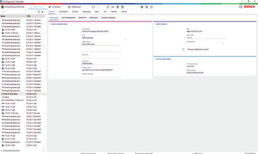
4.1 Overview
The Configuration Manager program allows you to adapt the general appearance of the user
interface to your needs, for example, the display of the navigation bar on the left side or on
the top.
Navigation bar to the left
1 Navigation bar 2 Device depending tabs
The displayed tabs depend on the
selected device in the device tree
structure.
3 Info bar 4 Quick indication bar
5 Expand navigation bar icon 6 Connect to Bosch Remote Portal
Expands the navigation bar and shows Allows you to connect to the Bosch
plain text beside the icons Remote Portal
7 Main navigation bar 8 Reload page / Save
(Network Scan, My Devices,
Preferences)
Bosch Security Systems B.V. User manual 2021.04 | V8 | DOC10 en | User interface Configuration Manager 7.40
9 Toolbar section (configurable) 10 Device tree structure with filter and
For example: Info, Live video, Table search option
View..., Logging...
11 Menu bar (File, Tools, Help) 12 Status bar
13 View pane
The display in the view pane depends
on the selected device in the device
tree structure and the selected device
depending tabs.
Navigation bar on the top
(numbering see table above)
4.2 Main navigation bar tabs
The navigation bar tabs allows quick access to the most important functions.
4.2.1 The Remote Portal tab
The Bosch Remote Portal application allows you to connect your devices securely to the Bosch
Remote Portal from anywhere without changes in the local network. Using the Bosch Remote
Portal application you can then configure and maintain your devices remotely, and you can
give end-customers mobile access permission to devices.
2021.04 | V8 | DOC User manual Bosch Security Systems B.V.Configuration Manager 7.40 User interface | en 11
Refer to
– Connecting to the Bosch Remote Portal, page 48
4.2.2 The Network Scan tab
The Network Scan tab shows all video IP devices supported by the Configuration
Manager program that are detected in the network.
Additional Information:
– The information about a device is shown in bold if the device is newly detected since the
last network scan.
– The information about a device is shown in red if the device has an IP address or a MAC
address that is already used by another device in the system. This might be the case, for
example, if several devices that have not yet been configured are connected directly after
one another.
– Additional information about the devices can be seen if you scroll to the right.
4.2.3 The My Devices tab
The My Devices tab shows all devices that had been manually allocated to the system.
Additional Information:
– The information about a device is shown in bold if the device is newly detected since the
last network scan.
– The information about a device is shown in red if the device has an IP address or a MAC
address that is already used by another device in the system. This might be the case, for
example, if several devices that have not yet been configured are connected directly after
one another.
– Additional information about the devices can be seen if you scroll to the right.
4.2.4 The Preferences tab
The Preferences tab allows you to access general and application-specific settings.
Here, you can carry out a basic configuration for Configuration Manager itself as well as for
other video IP devices.
This tab contains the following device depending tabs:
– Access tab
– Directories tab
– Network tab
– Video tab
– Security tab
– Logging tab
– Appearance tab
If necessary, expand the folders to get subordinate items.
Access tab
This tab contains the following groups:
– Access group
Bosch Security Systems B.V. User manual 2021.04 | V8 | DOC12 en | User interface Configuration Manager 7.40
Master password
Assign a password here that protects access to the Configuration Manager program. If
you do not enter anything in this field, the program will start without asking for a
password.
This password is only valid for the computer on which it was defined.
Password policy
We recommend that you use strong passwords to enhance the protection of your
computer against unauthorized access.
Saved credentials
Displays your credentials (user, username, password).
– Security group
Encrypt communication (defines the TLS connection preferences)
To define the TLS connection preferences, select the required levels.
– Optional
Encrypted connections (HTTPS) and non-encrypted connections (HTTP, RCP+) are
allowed.
No certificate validation is performed. The certificate requirement level is not
relevant.
The default protocol HTTP is used when adding devices to the system.
The VSDK security properties are set as follows: Allow unencrypted connections,
Allow unencrypted media exports, and Allow no forward secrecy.
– Preferred
Encrypted connections (HTTPS) and non-encrypted connections (HTTP, RCP+) are
allowed.
The certificate validation is performed. The certificate requirement level is relevant. If
validation failed a warning is displayed but a connection still possible.
The default protocol HTTPS is used when adding devices to the system.
The VSDK security properties are set as follows: Allow unencrypted connections,
Allow unencrypted media exports, and Allow no forward secrecy.
– Required
A communication with devices is only possible using HTTPS.
The certificate validation is performed. The certificate requirement level is relevant. If
validation failed an error message is displayed and no connection is established.
The default protocol HTTPS is used when adding devices to the system.
There are no changes in the VSDK program.
Certificate required level
To validate certificates, select the required levels.
– None: All certificates are accepted. No validation is performed.
– Valid: Only an end certificate validation is performed. The certificate must be valid
(standard validation procedure, time signature).
– Trusted: The entire chain validation is performed, The root CA certificate is used to
sign the certificate and must be trusted on machines where the validation is
performed.
– Issued by the CA: The entire chain validation is performed, The root CA certificate is
used to sign the certificate and the MicroCA program must be configured in
Configuration Manager program.
– Environment Factors group
Network
Allows you to select the kind of network (Dedicated network, Shared network, Internet).
2021.04 | V8 | DOC User manual Bosch Security Systems B.V.Configuration Manager 7.40 User interface | en 13
– Repository group
Seal configuration after backup
Allows software sealing on the device after configuration has been backed up.
Check seal integrity
Does an integrity check of the software seal on the device.
Check settings integrity
Does an integrity check of the configuration of the device.
Directories tab
This tab contains the following group:
– Directories group
Allows you to select the folders for:
– Screenshots
– Recordings
– Database
– Configuration repository
Network tab
This tab contains the following groups:
– Network Scan group
Run continuous network scan
Enable this option if the network is to be scanned at regular intervals.
Scan interval [s]
Enter the time interval in seconds for automatic scanning here, choosing a value between
10 and 3600 seconds (1 hour).
– Network Scan RCP+ group
Protocoll
In the Protocol list, click the protocol if you are using devices in various subnets.
This allows all devices that belong to a different subnet than the PC on which
Configuration Manager is installed to be included in the network scan. Otherwise you will
have to manually add these devices to the system.
Multicast operation requires a multicast-enabled network that uses the UDP and the
Internet Group Management IGMP protocols.
Note: To get a valid multicast configuration, configure only RTP ports. The multicast ports
may only have even port numbers, while the ports with odd numbers may not be used.
This is because the multicast protocols RTP and RTCP depend on each other. RTP uses
the even ports, while RTCP uses the next odd ports.
– Bosch Remote Portal group
In the URL box, enter the address of the Bosch Remote Portal. This allows you to connect
the Configuration Manager program to the Bosch Remote Portal page to perform remote
administration and maintenance tasks.
– IP address range group
Mode
In the Mode list, click the mode (On, Off, Allow, Deny).
In the From and To columns, enter the IP addresses, then select the protocol in the
Protocol column.
Video tab
This tab contains the following groups:
– Monitor group
Bosch Security Systems B.V. User manual 2021.04 | V8 | DOC14 en | User interface Configuration Manager 7.40
Encoder
Select whether the images should be displayed in video format (H.26x) or as constantly
updated screenshots (JPEG).
Refresh interval
Select how often the screenshots that are shown in the various tabs (for example,
Intelligent Video Analytics) are refreshed:
Continuous: Image is refreshed as often as possible.
0 seconds: Image is displayed once but not refreshed.
1 … 10 seconds: Image is refreshed accordingly.
– VCA group
Show default VCA live overlay
if selected, the VCA overlays will be displayed on all video windows where applicable.
Security tab
This tab contains the following groups:
– MicroCA group
Here you can create a CA certificate.
Create: Click Create. The Create CA dialog box is displayed.
To create a CA certificate, refer to:
– Configuring MicroCA using Smart Token, page 38
– Configuring MicroCA using USB file, page 40
Load: Click Load. The Load CA dialog box is displayed. You can load existing CA
certificates.
Signature Validity [days]: Select the validity of the certificate.
– User token group
Certificate store type: Click the Certificate store type list to display a list of existing
tokens known to your system.
To manage and create user tokens, refer to:
– Managing user token, page 45
– Creating user token, page 46
Logging tab
This tab contains the following groups:
– Device I/O group
Select the requird logs, for example, Log (read), Log (received), Log (message).
– RCP+ logging group
Enable RCP+ logging
Enable or disable the logging of RCP+ commands. A log file is created for every device in
the system.
Minimum numbers
Specify the maximum period for which you want the log data to be saved.
– ONVIF logging group
Enable logging
Enable or disable the logging of ONVIF commands. A log file is created for every device in
the system containing the time stamp, the URL, the ONVIF service and the command. The
output is displayed in the Device Communication Log dialog box.
– Miscellaneous group
Write time stamp
Select the check box to obtain the time stamps on the recordings.
Appearance tab
This tab contains the following groups:
2021.04 | V8 | DOC User manual Bosch Security Systems B.V.Configuration Manager 7.40 User interface | en 15
– Language group
Language
Select the display language.
Edit Toolbar:
Click and adapt the toolbar to your needs.
Config service enabled
Not applicable
– Startup group
Restore last view
If selected, the last view is displayed when Configuration Manager is restarted.
After confirmation only
If selected, the next time you start Configuration Manager you will be asked whether you
want to restore the last view.
– Database camera name group
Prefix device name to camera name
Displays the encoder device name before the camera name in the camera list if cameras
are integrated into the system over video encoders.
– Theme group
Navigation bar orientation
Select whether the navigation bar is displayed to the left or on the top.
Refer to
– Configuring MicroCA using Smart Token, page 38
– Configuring MicroCA using USB file, page 40
– Managing user token, page 45
– Creating user token, page 46
4.3 The Menu bar
This section describes special operational functions, tools and help functions.
4.3.1 The File menu
To get the File commands:
4 Click the File menu. The following commands are displayed.
Emulate Alien System... / Abandon Emulation
Imports the system image of an alien Configuration Manager system.
Export VDB
Allows you to export the database with the user defined password.
Close
Closes the Configuration Manager program. This also breaks the connection between
Configuration Manager and the server.
4.3.2 The Tools menu
To get the Tools commands:
Bosch Security Systems B.V. User manual 2021.04 | V8 | DOC16 en | User interface Configuration Manager 7.40
4 Click the Tools menu. The following commands are displayed.
Logging...
Displays the Device Communication Log dialog box.
Here, you can view the RCP+ commands that are transmitted by Configuration Manager when
connecting to devices, if you have enabled logging.
Device Allocator...
Displays the Device Allocator dialog box containing an overview of all available devices in the
network and all devices that are allocated to the system.
Snapshot Scan
Displays a dialog box containing a snapshot for each of the selected cameras. If you right-click
a snapshot, the commands are displayed relevant for the camera.
Device Health Monitor...
Displays the Device Health Monitor dialog box, that provides a quick overview of the status of
selected devices.
Save System Image
Saves the image of the current Configuration Manager system for emulation on a different PC.
Import .csv File…
Displays a dialog box that allows you to import .csv files.
Import Project Assistant File
Displays the Project Assistant Import dialog box where you can select the files to be imported.
Security and Safety Things Store
4.3.3 The Help menu
To get the Help commands:
4 Click the Help menu. The following commands are displayed.
Online Help...
Displays the Configuration Manager Help.
Online Help VRM...
Displays the Video Recording Manager Help.
Online Help IVA...
Displays the Intelligent Video Analytics Help.
2021.04 | V8 | DOC User manual Bosch Security Systems B.V.Configuration Manager 7.40 User interface | en 17
About...
Displays the About Configuration Manager dialog box, containing information on, for
example, the software components installed on this PC and the software version numbers of
the installed components.
4.4 Reload / Save icons
Reload page
Reloads device and page information and starts a device scan on the Devices tab.
Save
Saves any settings that have been configured for the selected device.
4.5 Toolbar icons
These icons allow quick access to several Configuration Manager functions.
Info
Displays detailed information about the selected device.
Live video
Displays the live video data from the selected device.
Configuration repository,,,
Display the Configuration repository dialog box showing device configuration information, for
example; device count notes, firware and hardware versions.
Table view
Displays the Table View dialog box containing the devices in table view.
Click again to close the Table View window.
Logging...
Displays the Device Communication Log dialog box.
Here, you can view the RCP+ commands that are transmitted by Configuration Manager when
connecting to devices, if you have enabled logging.
Device Allocator...
Displays the Device Allocator dialog box containing an overview of all available devices in the
network and all devices that are allocated to the system.
Import .csv File…
Displays a dialog box that allows you to import .csv files.
Bosch Security Systems B.V. User manual 2021.04 | V8 | DOC18 en | User interface Configuration Manager 7.40
Device Health Monitor...
Displays the Device Health Monitor dialog box, that provides a quick overview of the status of
selected devices.
Save System Image
Saves the image of the current Configuration Manager system for emulation on a different PC.
Snapshot Scan
Displays a dialog box containing a snapshot for each of the selected cameras. If you right-click
a snapshot, the commands are displayed relevant for the camera.
Import Project Assistant File
Displays the Project Assistant Import dialog box where you can select the files to be imported.
4.6 The Info bar
If a device is selected under the Network Scan or My Devices tabs, an info bar is displayed to
the right of the top navigation pane. This info bar provides you with brief information about
each selected device as follows:
– Device type
– Device IP address
Notice!
i The info bar is only available if the navigation bar is on the top.
4.7 The Quick indication icons
To display the quick indication icons:
4 Drag the pointer on the icons to view details on the processor load, network connection
and recording status:
Quick indication icon description
– The left icon indicates the proportions of the individual functions on the encoder load,
shown as percentages. For devices with two processors, a separate icon is shown for
each processor.
– The icon in the middle indicates the network connection type and the speed of the
outgoing (UL = Uplink) and incoming (DL = Downlink) data traffic.
– The right icon indicates information on the recording status.
– Green: active recording
– Red: error
– Orange: recording scheduler active, no current recordings
– Gray: recording scheduler not active, no current recordings
4.8 The Status bar
The status bar at the bottom edge of the window shows the following:
– In the central section: the number of detected, visible and selected devices.
2021.04 | V8 | DOC User manual Bosch Security Systems B.V.Configuration Manager 7.40 User interface | en 19
– In the central section: whether you are currently working Online, and whether or not
Configuration Manager is currently connected to a server. If it is connected to a server,
the server IP address is displayed. Otherwise the entry DB local appears here.
If you are emulating an alien system, the entry System emulation appears here.
– On the far right: the version number of Configuration Manager is displayed.
4.9 The View pane
The View pane for the Network Scan and My Devices tabs shows a series of subdivided tabs,
the number and content of which depend on the device selected in the list.
The tabs in the View pane can be used to make the configuration settings that the device also
provides in the Web browser view, some of them with a slightly different composition.
Access from Configuration Manager to the devices can be configured when selecting the
General and Unit Access tab (not necessary for web browser).
Detailed information about the configuration options for a device can be found in the relevant
device documentation and the online Help in the relevant Web browser view.
Notice!
i Changes only become active if you click the Save tab.
4.10 Used icons
The devices in the Network Scan or My Devices tabs are represented by the following icons:
Device icons
Camera
Device (for example, Encoder/Decoder/Streaming
Gateway)
Hardware recorder (for example, DIVAR)
Storage system (for example, DIVAR)
DomeCamera
iSCSI target
Video Recording Manager server
Video Recording Manager failover server
Video Recording Manager server for second
recording stream
Video Recording Manager failover server for second
recording stream
Unknown
Device status icons
The status of the icons is shown exemplarily by using a camera. Other devices are displayed in
the same manner
Bosch Security Systems B.V. User manual 2021.04 | V8 | DOC20 en | User interface Configuration Manager 7.40
Icon Color Status Online Authentication Secure Trusted
connection certficates
Camera grey OK No Unknown Unknown Unknown
Camera grey, Warning * No Unknown Unknown Unknown
exclamation mark
yellow
Camera grey, Error * No Unknown Unknown Unknown
exclamation mark
red
Camera grey, No access No No * Unknown Unknown
lock red
Camera blue OK Yes Yes No Not
relevant
Camera blue, Warning Yes Any No Not
exclamation mark relevant
yellow
Camera blue, Error Yes Any No Not
exclamation mark relevant
red
Camera blue, No access Yes No No Not
lock red relevant
Camera yellow OK Yes Yes Yes No
Camera yellow, Warning Yes Any Yes No
exclamation mark
yellow
Camera yellow, Error Yes Any Yes No
exclamation mark
red
Camera yellow, No access Yes No Yes No
lock red
Camera green OK Yes Yes Yes Yes
Camera green, Warning Yes Any Yes Yes
exclamation mark
yellow
Camera Green, Error Yes Any Yes Yes
exclamation mark
red
Camera green, No access Yes No Yes Yes
lock red
* Device was online
2021.04 | V8 | DOC User manual Bosch Security Systems B.V.Configuration Manager 7.40 User interface | en 21
Icons on the View pane
The following icons are used on the View pane:
Help. Click the icon to open context-related help.
Warning. This element contains important information.
Danger. This element contains very important information.
Info. Click the icon to display a camera's properties.
Connection established.
Connection lost.
Recording state: Device is recording.
Recording state: Device is not recording.
Relay state: Relay is in default state.
Relay state: Relay switched to alert state.
Locked: This element does not allow input or changes.
MicroCA icons
The following icons are related to the MicroCA functions:
Certificate icon: Shows the certificate status.
Signing icon: Click this icon to sign and upload a certificate.
User token icon: Click this icon to add a user token.
4.11 Shortcut menu
Right-click a device to open the shortcut menu. If you have selected multiple devices, not all
options in the shortcut menu are enabled.
The following provides an overview of the commands:
Select Group
(My Devices tab)
If several devices have been grouped, use this command to select all devices or cameras of
that group for editing.
Node > Expand Child Nodes
(My Devices)
Click to expand a group or site to see the devices and cameras assigned to it.
Node > Collapse Child Nodes
(My Devices tab)
Click to collapse a group or site to hide the devices and cameras assigned to it.
Bosch Security Systems B.V. User manual 2021.04 | V8 | DOC22 en | User interface Configuration Manager 7.40
New Device...
(My Devices tab)
Allocates a non-listed device to the system. This command is only active if you click the area in
the left pane in which no devices are listed.
Delete
(My Devices)
Deletes the selected device from the system.
Site
(My Devices)
Click to change a group to a site. Select the group first.
Add to System...
(Network Scan tab)
Allocates the selected device to the system. Before making an allocation, you can select a
group or create a new one.
This command corresponds to the Device Allocator dialog box.
Set Session Authentication...
(Network Scan tab)
If a selected device is protected by a password, you must authenticate yourself for that
device.
Configure...
Displays the respective configuration tool if installed.
Add iSCSI System... (VRM)
Displays the Add iSCSI System dialog box.
Here, you can add an iSCSI system to the VRM using the host IP address and the SNMP IP
address.
LUN Assignment... (iSCSI system)
Displays the LUN Assignment dialog box. Here, you can add individual LUNs to the system.
File Upload
– Firmware...
You can select the desired upload file and start the upload. Refer to the information
about firmware uploads in the documentation for the relevant device.
You can use this command to carry out a firmware upload for several devices at the same
time. You must ensure that all selected devices are of the same device type when you
carry out a firmware upload for several devices at the same time.
– SSL Certificate...
Upload an SSL certificate to the device to enable encrypted communication with the
device.
– Decoder Logo...
The decoder logo is the image displayed by the decoder if there is no connection to a
device. You can upload your own logo for this purpose. This must be in H.263 format.
Settings
(My Devices tab)
– Back up…
Allows you to save the camera configuration.
Click to open the Backup to Repository dialog box.
– Restore…
2021.04 | V8 | DOC User manual Bosch Security Systems B.V.Configuration Manager 7.40 User interface | en 23
Allows you to restore the camera configuration.
Click to open the Configuration repository dialog box.
– Transfer…
Transfers the camera configuration from one camera to another camera.
Click to open the Transfer Settings dialog box.
– Replace…
Replaces the configuration of a camera with configuration of another camera of the same
type.
Click to open the Device Replacement Wizard.
Device Network Settings...
(My Devices tab)
You will see the Network settings dialog box.
This dialog box is used to change the IP address, subnet mask and gateway of the selected
device or activate automatic IP assignment via DHCP.
This is only possible for devices that are not password-protected.
Show Live Video...
(My Devices tab)
A window opens, displaying the live video data from the selected device. You are offered
different display options depending on which device you selected.
Show in Web Browser...
(My Devices tab)
The live page of the Web browser view for the device is opened in the default browser.
Show Settings in Web Browser...
The configuration page of the Web browser view for the device is opened in the default
browser.
Device Info...
The dialog box containing device information is displayed.
Blink LED
(My Devices tab)
A LED on the device flashes. This allows you to check whether there is any communication
between Configuration Manager and the device. This command also helps you to identify a
device if several devices of the same type are installed at the same location.
Restart
(My Devices tab)
Initiates a reboot of the device. This is only possible for devices that are not password-
protected.
Ping
(My Devices tab)
Pings the selected device to confirm network communication with the device.
4.12 Blocked input fields
It is possible that some fields are blocked for editing. The causes for the block are indicated
by different entries in the fields.
If several devices are selected, some settings cannot be made.
The input fields are marked with a padlock.
Bosch Security Systems B.V. User manual 2021.04 | V8 | DOC24 en | User interface Configuration Manager 7.40
If a device is currently recording, some settings cannot be
modified. There is no difference between valid and invalid
authentication. Only a tooltip is shown. The input fields are
marked with a padlock. If necessary, stop the recording.
If there is an error, individual fields are marked accordingly.
The group labeling is included in the error message.
Input fields you are not authorized to change are marked by a
padlock and are blocked for editing.
Groups you are not authorized to change are marked by a
padlock and are blocked for editing.
2021.04 | V8 | DOC User manual Bosch Security Systems B.V.Configuration Manager 7.40 Working with Configuration Manager | en 25
5 Working with Configuration Manager
The following section offers a list of user actions for configuring hardware and software
components that can be performed using Configuration Manager.
5.1 Adding devices to the system
You can add devices and components to the system that are detected in the network.
5.1.1 Adding devices (for example, cameras, encoders)
To add devices to the system (for example, cameras, encoders):
1. On the navigation bar, click the Network Scan tab.
2. Select the device.
3. Click the General tab, then click the Unit Access tab.
4. In the Add To System group, click the Target group icon if necessary.
The Set target group dialog box is displayed.
5. Enter the name of the group or select the name from the list if you want to assign the
device to a group.
Note: You can also continue without selecting or creating a group.
6. In the Add To System group, click Add to system.
The device is added to the system.
7. Click the My Devices tab to display the device in the tree structure.
5.1.2 Adding iSCSI devices
To add iSCSI devices to the system:
1. On the navigation bar, click the Network Scan tab.
Note: The Configuration Manager program scans the network for compatible devices and
displays the decoder in the tree structure.
2. In the tree structure, right-click a device, then click Add to System....
The Add Device to System dialog box appears.
3. Enter the name of the group or select the name from the list if you want to assign the
device to a group.
Note: You can also continue without selecting or creating a group.
4. Click OK.
The device is added to the system.
5. Click the My Devices tab to display the device in the tree structure.
See also:
– Allocating devices, page 25
5.2 Allocating devices
Before working with Video Client, you must complete the allocation, as the program can only
access devices that have been allocated to the system.
Bosch Security Systems B.V. User manual 2021.04 | V8 | DOC26 en | Working with Configuration Manager Configuration Manager 7.40
5.2.1 Allocating listed devices
You can allocate all devices using the Network Scan tab. It is also possible to allocate devices
to the system by adding them to the My Devices tab. This simplifies configuration as you can
limit yourself to a relevant selection of available devices and clearly arrange the allocated
devices in groups.
To allocate listed devices using the Device Allocator icon:
1. On the navigation bar, click the Tools menu, then click Device Allocator .
The Device Allocator dialog box is displayed.
All devices detected in the network are displayed to the left, while those allocated to the
system appear to the right.
2. Drag the unallocated devices from the left to the right-hand side of the window.
3. If necessary, sort the list of entries. To do this, click the appropriate table header.
4. Click OK.
The devices are integrated into the system.
Notice!
i If it is not possible to integrate a device, a warning message appears.
See also:
– Creating groups, page 27
– Defining a group as site, page 28
5.2.2 Allocating unlisted devices
The Device Allocator dialog box also enables you to allocate devices to the system that were
not detected during the network scan.
Allocating an unlisted device:
1. On the navigation bar, click the Tools menu, then click Device Allocator .
The Device Allocator dialog box is displayed.
All devices detected in the network are displayed to the left, while those allocated to the
system appear to the right.
2. In the Device Allocator dialog box, right-click into the Allocated devices area (but not on
a device), then click New Device....
The Device Editor dialog box is displayed.
3. Enter the URL (for example, the IP address with the port number) of the device. The IP
address must previously have been set on the device.
4. In the Type list, select or select the device type from the list of supported
devices.
If you select an ISDN-compatible device, the field for the telephone number is also
activated.
5. Enter the telephone number for the ISDN connection if you want a device to be
connected using an ISDN line.
6. Click OK.
The device is listed as allocated device.
2021.04 | V8 | DOC User manual Bosch Security Systems B.V.Configuration Manager 7.40 Working with Configuration Manager | en 27
Notice!
i You can only allocate supported devices. In the tree structure of the Devices and My Devices
tabs, not supported devices are displayed dimmed or red.
See also:
– Creating groups, page 27
– Defining a group as site, page 28
– Used icons, page 19
5.3 Clearing device allocations
You can remove devices from the system at any time by clearing the allocation. The devices
are then no longer listed in the My Devices tab and can no longer be accessed in the Project
Assistant program.
To clear device allocations:
1. On the navigation bar, click the Tools menu, then click Device Allocator .
The Device Allocator dialog box is displayed.
All devices detected in the network are displayed to the left, while those allocated to the
system appear to the right.
2. Drag a device from the right to the left-side of the dialog box
or
right-click the device and click Delete.
3. Click OK.
Notice!
i Delete groups in the same way. If you delete a group, you also clear the allocation of all
devices that you have allocated to that group.
5.4 Creating groups
The Device Allocator dialog box enables you to clearly combine the devices into groups, for
example sorted by locations.
To create groups:
1. On the navigation bar, click the Tools menu, then click Device Allocator .
The Device Allocator dialog box is displayed.
All devices detected in the network are displayed to the left, while those allocated to the
system appear to the right.
2. In the Device Allocator dialog box, right-click into the Allocated devices area (but not on
a device).
3. Click New Group....
The Add New Group dialog box is displayed.
4. Enter a name for the new group.
5. Click OK.
The group is added to the list.
6. Drag a device from the list to the group name.
The device is added to the group and listed under the corresponding name.
Note: To remove a device from a group, drag the device from the group to the list.
Bosch Security Systems B.V. User manual 2021.04 | V8 | DOC28 en | Working with Configuration Manager Configuration Manager 7.40
7. Click OK.
The grouping is displayed in the device tree structure.
Note:
You can also create sub-groups by dragging a group to the name of another group in the
Device Allocator dialog box.
Additional Options
4 On the toolbar, click the My Devices tab, right-click the tree structure area (but not on
device), then click New Device....
See also:
– Defining a group as site, page 28
5.5 Defining a group as site
You can define a group as site to use it in Video Client.
Notice!
i Cameras that are assigned to a group are only available if the site is connected. That means,
for chargeable connections costs only arise in this case.
To define a group as site:
1. On the navigation bar, click the My Devices tab.
2. Right-click the group in the tree structure or in the Device Allocator dialog box, then click
Site.
The icon to the left changes from to .
To define a site as group:
1. On the toolbar, click the My Devices tab.
2. Right-click the site in the tree structure or in the Device Allocator dialog box, then click
Site.
The icon to the left changes from to .
5.6 Accessing the device
If a device is not currently communicating with the system, for example, because it is only
temporarily contactable or because a firewall is blocking communication, a message is
displayed in the view window.
In this case, Configuration Manager offers various setting options to enable communication
again.
IP address failure
Communication can fail because the device IP address has been changed (for example, using
the device's Web browser view) and Configuration Manager is still using the old IP address to
establish the connection.
To update the device tree:
1. On the navigation bar, click the Network Scan tab.
2. Click the Reload icon.
The Configuration Manager program scans the network for devices and displays them
with their current settings.
2021.04 | V8 | DOC User manual Bosch Security Systems B.V.Configuration Manager 7.40 Working with Configuration Manager | en 29
Device Access
If a firewall is blocking communication between the device and the Configuration Manager
program, you can change the transmission protocol:
To change the transmission protocol:
1. On the navigation bar, click the My Devices tab, then select the device.
2. Click the General tab, then click the Unit Access tab.
3. In the Device access group, select the transmission protocol from the Protocol list.
– RCP+
TCP transmission using port 1756
– HTTP
TCP transmission using preset port
– HTTPS
TCP transmission using preset port
4. If you have selected HTTP or HTTPS as the protocol, you must set the port to correspond
to the settings stored in the device.
5. Under Authentication, you can set up a password for a user name of the relevant device.
This means, the Configuration Manager program automatically accesses the device when
establishing a connection without disabling the password protection each time.
Notice!
i Do not use any special characters, for example &, in the password.
Special characters are not supported for the password and can prevent you from being able
to access the program.
5.7 Replacing devices
If devices must be replaced, most of the configuration for the new devices can be done
automatically using the Replacement function.
The Replacement function can only be used on devices that are allocated to the system - such
devices are displayed when clicking the My Devices tab.
To replace devices:
1. On the navigation bar, click the Preferences tab, then click the Directories tab.
2. In the Database folder box, enter the location in which configuration data is to be backed
up.
3. On the navigation bar, click the My Devices tab, right-click the device, click Settings,
then click Backu up….
The Backup to repository dialog box is displayed.
4. Select the Use global password and Seal configuration check boxes if needed, then click
Start.
The device configuration settings are saved locally on your PC.
5. Replace the device.
6. In the navigation bar, click the My Devices tab.
The replaced device is shown as not being configured.
7. Right-click the device, click Settings, then click Replacement....
The Device Replacement Wizard dialog box lists all devices that are the same type as the
replaced device and for which configuration data is saved.
8. Select the replacement device that was installed instead of the selected device.
Bosch Security Systems B.V. User manual 2021.04 | V8 | DOC30 en | Working with Configuration Manager Configuration Manager 7.40
9. Click Next >.
Automatic configuration is started.
10. You will be informed if the firmware version of the device and the configuration file differ.
You are able to download a new firmware version onto the device.
11. Click Next > again.
The Device Replacement dialog box is displayed, listing the selected device and
additional information.
12. Click Start.
The configuration files are transferred. If it is not possible to transfer all the data, the
number of data packets not transferred is listed in the Failed column.
Once the transfer is complete the device is rebooted so that the new settings take effect.
When the Cancel button is replaced by the Close button, the procedure is complete.
13. Click Close.
The Device Replacement Wizard dialog box is displayed again.
14. Click Finished to complete the procedure.
5.8 Defining storage locations
You can define the storage location for screenshots, recordings, configuration repository and
video analytics.
To define the storage location for screenshots, recordings, database and configuration
repository:
1. On the naviation bar, click the Preferences tab, then click the Directories tab.
2. In the relevant input field, enter the path for the storage location or click the icon to the
right of the input fields to select a folder.
Note:
You can select any directory that is available in the network.
Warning!
Do a regularly check that the selected directories have available storage capacity. Delete
! recordings no longer required.
5.9 System emulation
The complete system configuration can be saved as a system image and emulated using a
different Configuration Manager application. This function helps you to isolate problems
without having to access the actual system.
To save a system image:
1. On the the navigation bar, click the Tools menu, then click Save System Image....
The Save System Image dialog box is displayed.
2. Select the storage location and enter a name for the zip file.
3. Click Save.
To emulate an alien system:
1. Save the zip file containing the image of the alien system to your PC.
2. On the the navigation bar, click the File menu, then click Emulate Alien System....
The Choose Alien System dialog box is displayed in which you can select the storage
location and the image file.
2021.04 | V8 | DOC User manual Bosch Security Systems B.V.Configuration Manager 7.40 Working with Configuration Manager | en 31
3. Click Open.
The emulation is performed automatically. The message System emulation appears in the
status bar.
4. Click the File menu, click Abandon Emulation to return to your own system.
The message System emulation disappears in the status bar.
5.10 Notes on multiple configuration
It is possible to select multiple devices and then simultaneously make settings for all selected
devices. In this way, CCTV systems can be set up quickly and efficiently.
To configure multiple devices:
1. On the navigation bar, click the Network Scan or My Devices tab.
2. In the tree structure, select the devices.
3. In the View pane, select the tab in which you want to make changes.
The following special features are available for multiple selections:
– Input fields that can only be changed for individual devices (for example, Device IP
address) are blocked.
– Input fields where the settings for the selected devices differ because of their type
(for example, recording planning for different video senders) are blocked.
– Input fields that already have identical settings for all selected devices show these
settings.
– Input fields containing different entries for the selected devices show or
M.
– Options that are only activated (checked) for some of the selected devices are
indicated by a green square.
4. Change the settings as desired.
5. Click Save.
Changed input fields that previously contained or M now display the uniform
value.
6. Continue for all other tabs in which you want to make changes.
5.11 Configuring the toolbar section
You can adapt the toolbar section in the navigation bar individually to your needs.
Notice!
i Do not use any special characters, for example &, in the password.
Special characters are not supported for the password and can prevent you from being able
to access the program.
To adapt the toolbar section to your requirements:
1. On the navigation bar, click the Preferences tab.
2. Click the Appearance tab
3. In the General group, click Edit Toolbar…. The Toolbar Settings dialog box is displayed.
4. Select an entry, then click the arrow buttons to move the entry from the Available
actions list to the Showed actions list or vice versa.
Note:
If necessary, click Default to get the original settings.
5. Click OK.
Bosch Security Systems B.V. User manual 2021.04 | V8 | DOC32 en | Working with Configuration Manager Configuration Manager 7.40
5.12 Getting device information
The Configuration Manager program gives you easy access to all devices in the network. You
can quickly get all information you need for each device.
To get device information:
1. On the navigation bar, click the Network Scan or My Devices tab.
2. Right-click a device, then click Device Info... . The device information are displayed.
Additional options:
– The info bar above the view pane shows the name, device type and IP address. For
hardware devices, it also gives information on the processor load, network connection
and recording status.
– The tabs in the view pane show all available configuration.
5.13 Disabling network scan
If you do not want to use the automatic network scan, you can disable it. Note that in this case
the status of the devices will not be updated regularly.
Regardless of the default setting, you can trigger a network scan manually at any time.
To disable the automatic network scan:
1. On the navigation bar, click the Preferences tab.
2. Click the Network tab.
3. In the Network Scan group, clear the Run continuous network scan check box.
To trigger a network scan manually:
1. On the navigation bar, click the Network Scan tab.
2. Click the Reload page icon.
5.14 Using the Table view
The table view provides the option of presenting a summary of specific settings for individually
selected devices in the form of a clearly arranged table.
The content of all main tabs and sub-tabs can be exported in *.csv format.
To open the table view:
1. On the navigation bar, click the Network Scan or My Devices tab.
2. On the navigation bar, click the Table view icon.
The Table View window is displayed. The table contains a column to the left with all
devices and cameras.
In the view pane to the right, all well-known main tabs (for example, General, Camera:,
2021.04 | V8 | DOC User manual Bosch Security Systems B.V.Configuration Manager 7.40 Working with Configuration Manager | en 33
etc.) and sub-tabs (for example, Unit Access, Date/Time, etc.) are displayed.
3. If necessary, minimize the amount of displayed devices and cameras as follows:
– In the Filter dialog box, enter an appropriate filter. To delete the filter, click the
icon.
In table view you can also define your own custom views.
To define a custom view:
1. On the navigation bar, click the Network Scan or My Devices tab.
2. In the tree structure, select one or more devices or cameras.
3. On the navigation bar, click the Table view icon.
The Table View window with all devices is displayed. And also the Customs view tab and
the default tab where you can add your first view with specific parameters.
To rename the default tab, double-click the tab, then enter an appropriate name.
To add further views, click the + sign. A New page tab for the next view is displayed.
To rename the New page tab, double-click tab, then enter the new name.
4.
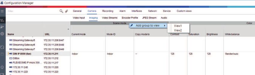
5. Add groups to your custom view as follows:
Select a device, then click one of the main tabs and a sub-tab (for example, Camera >
Imaging.
Right-click a group (for example, Scene mode), then click Add group to view and select
the view the group should appear.
Bosch Security Systems B.V. User manual 2021.04 | V8 | DOC34 en | Working with Configuration Manager Configuration Manager 7.40
Note: A new column Camera identification group is added to your custom view.
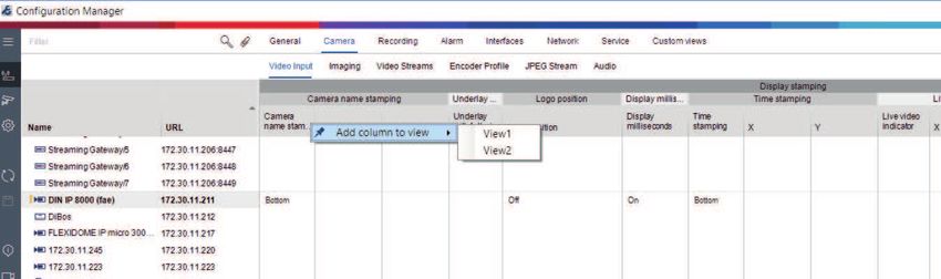
6. Add elements to your custom view as follows:
Select a device, then click one of the main tabs and a sub-tab (for example, Camera: >
Video Input).
Right-click an element (for example, Camera name stamping), then click Add column to
view and select the view the element should appear.
Note: A new column Camera name stamping element is added to your custom view.
7. Add more columns to the custom view in this way
Note: Not all groups or elements can be added to the custom view.
8. If necessary, add more devices or cameras to the table.
9. In custom view, click a field in the table. You can set actions or parameters for individual
devices or cameras directly from here.
Importing and exporting .csv files
Export
In the Table View window:
On the navigation bar, click to export the content of the different Table View tabs as .csv file.
2021.04 | V8 | DOC User manual Bosch Security Systems B.V.Configuration Manager 7.40 Working with Configuration Manager | en 35
Import
In the Table View window:
On the navigation bar, click to import the stored content of Table View tabs.
Additional options in the Table View
– Sorting the table:
Click a column header to sort the table.
– Device commands:
Right-click one of the devices.
– Removing a column:
Right-click a column header, then click Remove....
Refer to
– Reload / Save icons, page 17
5.15 Importing .csv files
The Configuration Manager program allows you to import .csv files with additional attributes.
The .csv file must at least contain:
– A headline with column definitions
– 1 line with a device
The headline of the .csv file defines the mapping of the columns to the artefacts in the
Configuration Manager program. Information above the headline will be ignored during import.
Possible values are:
– Level: Creates a folder. If folder is already present, no folder will be created. Level may
appear several times to create folder-structures.
– Site: Creates a folder, that is flagged as site. This is only allowed to appear once per line.
– Attribute (name): Defines an attribute column with the attribute name in brackets.
– ConnectionString: Creates a device by connecting to the URI specified.
– DeviceName: Name of the device.
– User: Username for authentication.
– Password: User password for authentication.
To import a .csv file:
1. On the navigation bar, click the Network Scan or My Devices tab.
2. On the navigation bar, click the Tools menu, then click Import CSV-File…
The Import Data dialog box is displayed.
3. Click Browse, then select the .csv file you want to import.
Example: .csv import file
4. If needed, select the Add online devices only and the Empty current database before
import check boxes.
Bosch Security Systems B.V. User manual 2021.04 | V8 | DOCYou can also read