Crosstalk Suppression for Fault-tolerant Quantum Error Correction with Trapped Ions
←
→
Page content transcription
If your browser does not render page correctly, please read the page content below
Crosstalk Suppression for Fault-tolerant Quantum Error
Correction with Trapped Ions
Pedro Parrado-Rodríguez1 , Ciarán Ryan-Anderson1,2 , Alejandro Bermudez3 , and Markus Müller4,5
1
Department of Physics, College of Science, Swansea University, Singleton Park, Swansea SA2 8PP, United Kingdom
2
Honeywell Quantum Solutions, 303 S. Technology Ct., Broomfield, Colorado 80021, USA
3
Departamento de Física Teórica, Universidad Complutense, 28040 Madrid, Spain.
4
Institute for Theoretical Nanoelectronics (PGI-2), Forschungszentrum Jülich, 52428 Jülich, Germany
5
JARA-Institute for Quantum Information, RWTH Aachen University, 52056 Aachen, Germany
Physical qubits in experimental quan- 1 Introduction
arXiv:2012.11366v2 [quant-ph] 24 Jun 2021
tum information processors are inevitably
exposed to different sources of noise and
Quantum computation aims at manipulating del-
imperfections, which lead to errors that
icate entangled states to achieve functionalities
typically accumulate hindering our abil-
beyond those presented by classical devices. Ro-
ity to perform long computations reli-
bust large-scale quantum computers will likely
ably. Progress towards scalable and ro-
require quantum error-correction (QEC) to ex-
bust quantum computation relies on ex-
ploit the wide range of applications offered by a
ploiting quantum error correction (QEC)
universal quantum processor [1]. In particular,
to actively battle these undesired effects.
scalable quantum error correction codes (QECCs)
In this work, we present a comprehensive
preserve quantum information by encoding it re-
study of crosstalk errors in a quantum-
dundantly in a set of physical qubits [1] such that,
computing architecture based on a single
in principle, arbitrary levels of protection can be
string of ions confined by a radio-frequency
achieved by increasing the number of redundant
trap, and manipulated by individually-
physical qubits while employing active detection
addressed laser beams. This type of er-
and correction of errors, provided physical noise
rors affects spectator qubits that, ideally,
rates lie below the critical threshold of the corre-
should remain unaltered during the ap-
sponding QECC. Together with a fault-tolerant
plication of single- and two-qubit quan-
methodology [2], which forbids the uncontrolled
tum gates addressed at a different set of
proliferation of errors by the specific design of the
active qubits. We microscopically model
scalable QEC circuits, this yields one of the most
crosstalk errors from first principles and
promising approaches towards large-scale quan-
present a detailed study showing the im-
tum computation. However, to achieve the re-
portance of using a coherent vs incoher-
quired levels of protection, there are experimen-
ent error modelling and, moreover, dis-
tal and theoretical challenges that need to be ad-
cuss strategies to actively suppress this
dressed. In particular, identifying and mitigating
crosstalk at the gate level. Finally, we
noise sources so that minimal QECCs are shown
study the impact of residual crosstalk er-
to outperform their physical/bare counterparts is
rors on the performance of fault-tolerant
considered a break-even point in the road-map for
QEC numerically, identifying the exper-
realising QEC for large-scale quantum computers
imental target values that need to be
[3, 4].
achieved in near-term trapped-ion exper-
iments to reach the break-even point for In several qubit-based quantum processors [5],
beneficial QEC with low-distance topolog- the implementation of some of the building blocks
ical codes. of QEC, such as the encoding of information in a
QECC and the detection and correction of errors
without altering the encoded information, has
been demonstrated, for example, using trapped
Accepted in Quantum 2021-06-18, click title to verify. Published under CC-BY 4.0. 1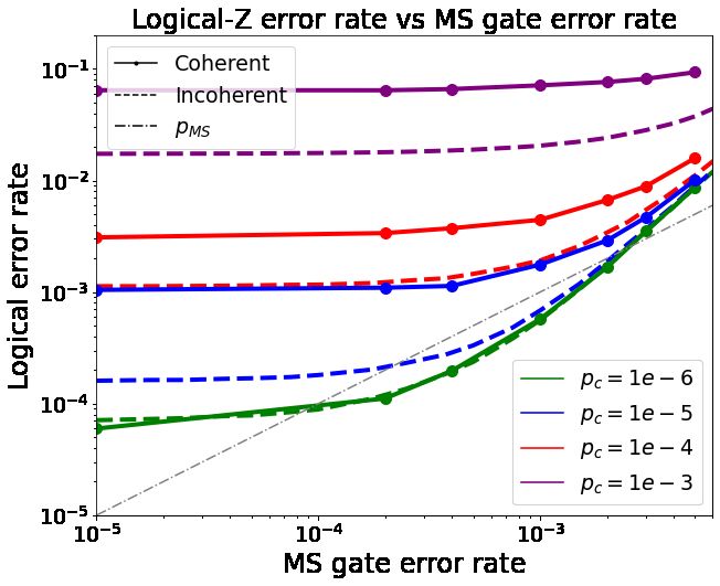
ions [6–15], superconducting circuits [16–20], nu-              designed such that the physical qubits only need
clear magnetic resonance [21, 22], or nitrogen-                 to be manipulated locally, i.e. requiring inter-
vacancy centres [23, 24]. Recently, and in parallel             actions between neighbours. Local errors that
to these efforts, there has also been much progress             stem from such manipulations can then be effi-
in protecting quantum information in oscillator-                ciently detected and corrected by the QECC. To
based bosonic QEC encodings (see, e.g. [25, 26]                 achieve this scalable protection, the lattices where
using trapped ions [27–29] and superconducting                  the physical qubits reside must be enlarged, and
setups [30, 31]).                                               the fidelity of the operations on the physical
                                                                qubits needs to be reduced below the aforemen-
   In this study, we will focus on qubit-based QEC
                                                                tioned threshold. Some experiments have already
with trapped ions. To date, trapped-ion experi-
                                                                demonstrated levels of control on the required
ments have shown high fidelity gates and long
                                                                regime for small systems (e.g. [34]), but scaling
coherence times [32–38], making them one of the
                                                                up the experiments while maintaining the desired
most promising candidates for the future reali-
                                                                degree of precision remains a challenge. To tackle
sation of large-scale quantum computers. There
                                                                this, various low-distance QEC codes at the reach
are currently two approaches for the scalability of
                                                                of different state-of-the-art technologies, are be-
trapped-ion systems for QEC. The first approach
                                                                ing actively investigated. For such low-distance
is the single-string ion trap, where all the ions
                                                                codes, it is of primary importance to use fault-
are placed in modules consisting of a single, linear
                                                                tolerant (FT) circuit designs so that errors do
radio-frequency trap, and coupled by photonic in-
                                                                not proliferate due to unsuitable circuit layouts,
terconnects [39, 40]. On the other hand, there is
                                                                allowing to exploit the full correcting power of
a so-called shuttling-based approach to scalabil-
                                                                the QECC. Such fault-tolerant circuit construc-
ity [41], which utilises microfabricated traps. In
                                                                tions will serve the purpose of reaching the break-
this approach, the ions are moved between stor-
                                                                even point of the advantage of QEC in small de-
age and manipulation zones, where they are sub-
                                                                vices and provide crucial information that can
jected to single-qubit gates and fluorescence mea-
                                                                guide future strategies in progress towards large-
surements as needed or otherwise merged with
                                                                scale quantum computers. The 7-qubit colour
other ions to implement entangling gates or sym-
                                                                code [52], also known as the Steane code [55],
pathetic laser cooling. After applying the desired
                                                                is one of the workhorses for such low-distance
sequence of operations, the ions can be split and
                                                                QECCs, and various techniques for an FT syn-
shuttled back to the storage zones. There they
                                                                drome readout have been devised [56, 57]. Due
remain as spectators of the operations on other
                                                                to present experimental capabilities, there has
active ions in the manipulation zones [8, 10, 41–
                                                                been intense recent activity developing resource-
45]. Our study is motivated by new experimen-
                                                                efficient FT schemes, such as FT readout tech-
tal capabilities that have recently emerged in the
                                                                niques that exploit a single ancilla for certain
single-string trapped-ion modules. These new ex-
                                                                types of microscopic noise [58–61]. Another ex-
perimental capabilities include the possibility to
                                                                ample is using the so-called flag-based readout
perform high-fidelity entangling gates addressed
                                                                [53, 62–64], which substantially reduces the num-
on specific subsets of ions [46–48] , leading to ef-
                                                                ber of required ancillary qubits, encompassing
fective all-to-all connectivity for two-qubit entan-
                                                                noise models beyond the single-qubit limit. These
gling gates. These capabilities have motivated
                                                                FT constructions exploit the full correcting power
the study of the single-string ion trap scenario
                                                                of the 7-qubit colour code, which allows for the
as a viable approach to implementing an oper-
                                                                correction of any single fault in the encoded log-
ational logical qubit [8, 49]. Informed by these
                                                                ical qubit. In turn, this yields a different scal-
results, we focus our study on the single string
                                                                ing of the logical error rate to the physical error
ion traps, which can eventually be combined
                                                                rate, which allows for the existence of pseudo-
with the shuttling-based or photonic-interconnect
                                                                thresholds and is crucial for the demonstration of
techniques for further scalability.
                                                                the advantage of QEC with small-scale devices.
  Topological codes [50–54], a specific class of                Colour codes distinguish themselves from other
scalable QECCs, are currently being studied as                  existing QECCs because of their capability of a
one of the main options for future QEC as they                  transversal implementation of the entire group of
have high error thresholds. Moreover, they are

Accepted in   Quantum 2021-06-18, click title to verify. Published under CC-BY 4.0.                               2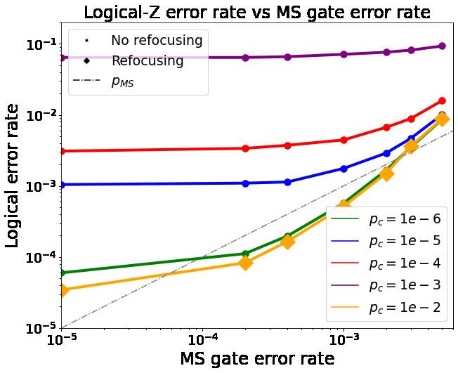
Clifford gates [52].                                            [75–80].
                                                                   Generally, one can attempt to mitigate errors
   Another important aspect for the progress of
                                                                in the whole computation at different levels, such
QEC is to inform the theoretical descriptions,
                                                                as at the level of gates [77, 81–85], circuits [62–
which typically assess a particular QECC under
                                                                64], full QECCs [53], or even entire algorithms
a specific noise model, with experimental results
                                                                [72, 76]. Recent work [70] has described how
such that the noise model can be made as real-
                                                                to combat crosstalk in ion traps on the level of
istic as possible. In the context of trapped ions,
                                                                QECCs and circuits by choosing the arrangement
a recent effort along these lines has been accom-
                                                                of qubits in the QECC circuitry to minimise the
plished for the shuttling-based approach [8, 65–
                                                                fault-tolerant breaking effects of crosstalk, and by
67] as well as for the single-string approach [68–
                                                                comparing the performance of different QECCs
70]. In this manuscript, motivated by the recent
                                                                in the compass-code QEC family. As a com-
developments of new addressing optics [46, 48],
                                                                plementary approach, we will investigate a tech-
which allow addressing subsets of ions in strings,
                                                                nique that suppresses crosstalk directly at the
we focus on the single-string approach. Specifi-
                                                                gate level. Gate-level mitigation of noise can
cally, we present a microscopically-motivated er-
                                                                suppress and change the nature of any remain-
ror model that accounts for imperfections in all
                                                                ing effective noise. Thus, one may want to con-
the required operations. A particular focus is
                                                                sider such techniques when evaluating the per-
placed on crosstalk errors. As described in [71],
                                                                formance and merits of different QEC protocols.
crosstalk errors cause undesired dynamics that
                                                                In particular, we will concentrate on a flag-based
violate either (or both) of two principles: spa-
                                                                scheme [64] for the distance-three seven-qubit
tial locality (i.e. gates should only affect the tar-
                                                                colour code. Our purpose is to analyse whether
get qubits) and independence of local operations
                                                                the refocussing technique, to be described in de-
(i.e. the effect of a gate should be independent of
                                                                tail below, allows this QEC-operated logical qubit
other gates being applied to the system). In ion
                                                                to outperform a physical qubit in the presence of
traps, crosstalk is caused by residual illumination
                                                                microscopic errors that include crosstalk. Here,
of laser light on neighbouring ions when applying
                                                                we want to identify the specific regimes where
single- and two-qubit gates. This error source can
                                                                this QEC advantage becomes possible, inform-
be effectively minimised for single-qubit gates [6]
                                                                ing future hardware improvements. We will also
using composite pulse sequences and dynamical
                                                                explore the consequences of the coherent nature
decoupling techniques [72] but becomes a more
                                                                of crosstalk and the extent to which it is pos-
delicate issue when arising in the context of two-
                                                                sible to suppress its impact on QEC. We con-
qubit entangling gates. With the use of carefully
                                                                sider near-term noise rates and crosstalk, build-
constructed pulse sequences, it is possible to sup-
                                                                ing on previous works [67], and extend the noise
press unwanted couplings on multi-qubit coupling
                                                                models towards a more complete description. It
operations, as shown in [73, 74]. In this work,
                                                                should be noted that although our study focuses
we consider two different models of crosstalk er-
                                                                on a trapped-ion quantum processor and the ex-
rors caused by this residual illumination. In
                                                                ample of the 7-qubit colour code, the error miti-
the context of fault-tolerant quantum computa-
                                                                gation technique and analysis discussed here can
tion (FTQC), fault-tolerant constructions assume
                                                                be adapted to other quantum processor architec-
that errors only happen on those qubits that are
                                                                tures, or other QECCs and algorithms.
involved in the gates. Thus, crosstalk represents
an error source that potentially breaks the fault-                 The organisation of this paper is as follows. In
tolerant character of FT circuit constructions, as              Section 2, we present the ion-trap operation tool-
it can induce error processes affecting groups of               box, examine the error model for the ion trap, and
physical qubits that would, otherwise, not inter-               review the QEC protocol we will be focusing on.
act through the gates. In this way, the FT design               Most importantly, we introduce two error models
of the circuits is compromised, possibly leading to             of crosstalk used throughout the remainder of the
the proliferation of errors. Therefore, if crosstalk            paper. In Section 3, we discuss how unmitigated
is not adequately accounted for, or suppressed, it              crosstalk affects the performance of the QEC pro-
can have a damaging effect on the performance                   tocol. In Section 4, we describe the refocussing
of the QEC protocol and break fault tolerance                   technique intended to suppress crosstalk and de-

Accepted in   Quantum 2021-06-18, click title to verify. Published under CC-BY 4.0.                               3
q q q
rive the form and strength of residual crosstalk
p
{ 1 − p1q I, p1q /3 X, p1q /3 Y, p1q /3 Z},
noise after applying the refocussing technique. where we have introduced the error rate per
We then examine how refocussing improves the single-qubit gate p1q , the value of which depends
performance of the QEC protocol by extensive on the sources of gate imperfections listed above,
numerical simulations. Finally, in Section 5, we and will be fixed to realistic values as achieved
briefly discuss further avenues for crosstalk miti- in current experiments, and as detailed below.
gation and present our conclusions. For multi-qubit entangling operations, a popu-
lar and widely used two-qubit entangling gate for
optical qubits is known as the Mølmer–Sørensen
2 Trapped-ion toolbox for QEC (MS) gate [88–90]. This gate equips the static
string with complete qubit connectivity, as it ex-
ploits a common vibrational mode as a quantum
2.1 Static ion-string gate set and noise model data bus, which can mediate the entangling gate
We focus on the single-string ion trap approach operation between an arbitrary pair (or larger
and a single ion species, allowing one to en- groups) of qubits that share this common mode,
code qubits in an optical transition that can provided that the laser beams uniformly illumi-
be operated with addressed laser light in the nate this pair (or group) and do not illuminate
visible spectrum. For example, in 40 Ca+ ions, the remaining ions. For this work, we concern
the |0i state corresponds to the ground state ourselves only with the MS gate in the XX-basis
which, when addressed to the pair of ions with
E
S1/2 , mj = −1/2 , and the |1i state to the
E indexes i, j within the static string, can be ex-
metastable excited state D5/2 , mj = −1/2 . We pressed through the following unitary
now briefly catalogue the set of physical gates
θ
we will utilise for these optical qubits in a XXij (θ) = exp −i Xi Xj , (3)
2
static-string ion trap to implement QEC. Refer-
ences [67, 86] provide a more detailed review of where Xi Xj is a tensor product of Pauli X-type
these gates. operators on qubits i and j, and θ is the MS-gate
angle. We focus on this version of the MS gate
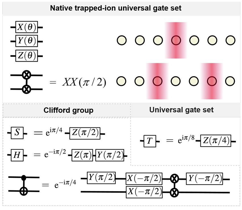
2.1.1 Single and two-qubit gates because the fully-entangling MS gate XXij (π/2),
together with single-qubit rotations, are sufficient
For single-qubit gates, ions in the string can be to enact the CNOT gate (see Fig. 1), which is the
individually addressed with laser beams [87] to two-qubit gate most often used to describe QEC
apply a rotation circuitry [91, 92].
These gates allow the implementation of the
θ
universal set of unitaries {H, S, T, CN OT } [93]
Pi (θ) = e−i 2 Pi , (1) by using combinations of the MS gate and single-
qubit rotations (see Fig.1 for more details). Fur-
where P ∈ {X, Y, Z} belongs to the set of Pauli thermore, for the static-string approach with
matrices, and θ is the angle of rotation. The er- single-ion laser addressing, the system has full
rors in the single-qubit gates stem from fluctu- two-qubit connectivity with this gate set. This
ations in the laser beam’s intensity and phase, allows for a better connected system of qubits,
which lead to over/under-rotations and changes which benefits the performance, reducing the
in the axis of rotation, respectively [66]. In the number of gates required to reproduce a general
present work, we model these errors by a symmet- circuit [49].
ric depolarising channel, which admits a decom- The error model for the MS gate finds its
position in terms of Kraus operators [1], namely sources in the residual spin-phonon entanglement
with the different levels of oscillation of the ion
chain, as well as fluctuations on the intensity and
Kn ρKn† .
X
ρ → D(ρ) = (2)
phase of the laser beam and the global magnetic
n
fields - see [34] for a recent comprehensive anal-
For the depolarising channel, ysis. An effective error model was derived in
the Kraus operators are Kn ∈ [67] from microscopic sources and consists of the
Accepted in Quantum 2021-06-18, click title to verify. Published under CC-BY 4.0. 4stochastic application of Pauli-type errors. The the measurement process also leads to the scatter-
details of this error model can be found in Ap- ing of photons from the measured ions, which can
pendix B. subsequently interact with the remaining specta-
Additionally, as discussed below, the MS gate tor ions in the string. We note that it is possible
error model includes crosstalk between the gate to prevent this type of crosstalk by applying spec-
ions and the neighbouring ions. troscopic decoupling pulses to nearby spectator
ions [6], such that the scattered photons become
off-resonant and the crosstalk is minimised (see
Appendix A.5). Therefore, in the following, we
will only focus on crosstalk in MS-gates.
In the entangling crosstalk model, the leading
order effect of crosstalk, as deduced by our micro-
scopic analysis (see Appendix A), is the partial
application of MS operations between the set of
gate ions and the set of neighbouring ions (Fig. 2).
For an MS-gate rotation of an arbitrary angle θ,
the leading order noise can be expressed as a uni-
tary that involves active qubits and neighbouring
spectators of the following form
θ
Y
E(θ)crosstalk = exp −i CT Xg XN .
g∈G,
2
Figure 1: Gate set for the static ion-string approach: N ∈neig(G)
By using addressed single-qubit rotations and the two- (4)
qubit entangling MS gate, we have a universal gate set
where G = {i, j} is the set of gate qubits the
available. The gate compilation of the CNOT gate using
the MS gate and single-qubit rotations is not unique. For ideal MS gate acts on, neig(G) is the set of qubits
other useful gate compilations, see [92]. that are neighbours to i and/or j but do not in-
clude i or j, and CT = Ωn /Ω depends on the frac-
tion of the light intensity illuminating the specta-
2.1.2 Crosstalk errors tor qubits with respect to the intensity addressed
to the active qubits. We do not consider any ef-
In general, crosstalk noise arises from any gate fects of crosstalk on next to nearest neighbours, as
that unintentionally affects qubits that should we assume a sufficiently narrow Gaussian profile
not be involved and should thus remain mere of the laser light. The amplitude of the electric
spectators. Operational crosstalk in optically- field away from the ions becomes exponentially
manipulated trapped-ion systems stems from im- suppressed, and therefore we neglect the effects
perfect addressing, such that light intended to be of crosstalk beyond nearest neighbours. In par-
addressed to a specific set of active qubits also ticular, Ω is the Rabi frequency for the two-ion
illuminates some spectator qubits, which are the MS gate and Ωn is the relative Rabi frequency of
qubits arranged in the immediate neighbourhood the residual light on the neighbouring ions. For
of the active qubits. The origin of this imperfect a single gate-neighbour crosstalk pair of a gate
addressing is generally given by the finite size of qubit g and a neighbouring qubit n, the error
the laser focusing spot at the position of the ions. channel is ρ → D2q ct (ρ), where
In this work, we consider two different models
for crosstalk errors in the MS gate: the entan-
ct θCT
gling crosstalk model and the Stark-shift crosstalk D2q (ρ) = cos2 2 ρ
model. It should be noted that whereas single-
θCT
+ sin2 2 Xg Xn ρ Xg Xn
qubit gates also generate crosstalk, this noise can
be greatly suppressed by techniques such as com- 1
+ i sin (θn ) [ρ, Xg Xn ]. (5)
posite sequences [94] or dynamical decoupling [81] 2
(see Appendix A for a further discussion). The In this expression, we can identify the proba-
qubit measurement can also lead to crosstalk, as bility of a single crosstalk-error event as pc =
Accepted in Quantum 2021-06-18, click title to verify. Published under CC-BY 4.0. 5sin2 (CT θ/2), which leads to a correlated 2-qubit
bit-flip error on one of the active qubits and a
π
(2) Y
neighbouring spectator qubit. It is clear from Ecrosstalk = exp −i µn Zn , (7)
4
this perspective that the entangling crosstalk er- n∈neig(G)
ror model should be carefully considered in the
context of the FT circuit design, as a single MS- where we use the same notations as in Eq. (4) and
gate error can turn into a dangerous pair of errors introduce µn as the residual ac-Stark shift from
if both the active and the spectator ions belong the off-resonant sidebands that act on the specta-
to the set of physical data qubits. tor ions due to crosstalk. A detailed derivation of
We can use this probability pc to define a this error model can be found in Appendix A.4.
stochastic/incoherent version of the crosstalk An incoherent approximation of this second
channel described in Eq. (5). That is, the Kraus crosstalk noise model, suitable to be used in
decomposition of Eq. (2) for incoherent crosstalk stabiliser-based numerical simulations, is given by
is a single-qubit dephasing channel with the follow-
ing Kraus decomposition (2) on each of the neigh-
p bouring spectator qubits
Kc,0 = 1 − pc I,
√ (6)
Kc,1 = pc Xg Xn . p
When an ion lies in between two gate ions, it Kc,0 = 1 − pc I,
√ (8)
will receive twice the residual light from the Kc,1 = p c Zn ,
gate. For that case, the probability of crosstalk
is effectively increased by a factor of 4. Note with pc = sin2 (µn π/4).
that we model both incoherent and coherent
crosstalk, as we will compare both models in the
simulations. The coherent nature of crosstalk
can have important implications for QEC per-
formance. On the one hand, it can lead to a
coherent build-up of errors. On the other hand,
the coherent nature also offers the possibility
to greatly suppress crosstalk using refocussing
schemes, as discussed in the following sections.
The second crosstalk model we consider is as- Figure 2: Addressed entangling gates in the static
sociated with an alternative way of implementing ion string approach: a) Light is focused on the ions i
and j encoding the qubits involved in the 2-qubit gate.
addressed entangling MS gates. Here, the idea is
b) Residual light on ‘neighbour’ ions in the direct spa-
to apply a power imbalance between the inten- tial vicinity of the target ‘gate’ ions causes small residual
sities of the bichromatic light fields coupling to crosstalk between the gate and neighbouring spectator
the red and blue phonon sidebands, respectively. ions. c) These interactions result in residual effective
This difference in intensities leads to an ac-Stark two-body interactions between each target (gate) ion
shift, which will differ for active and spectator and each of the neighbouring spectator ions (indicated
ions. By tuning the power imbalance appropri- by dashed lines). The form and quantitative dependence
ately, the gate qubits will be subjected to a two- of these crosstalk terms are discussed in the main text.
d) Circuit representation of the MS gate (solid line) and
photon resonance and undergo the ideal MS gate
crosstalk events (dashed lines) resulting from the gate
dynamics, as desired, in contrast to the specta- using the entangling error model for crosstalk, as de-
tor ions that will effectively be exposed to weak scribed in the text.
and far off-resonant light. As a consequence, this
setting avoids entangling interactions of specta-
tor qubits with the active ions. The leading-
2.1.3 Errors on idling qubits
order effect of the residual crosstalk is an ac-Stark
shift on the spectator ions, resulting in small un- We consider here trapped-ion qubits encoded in
wanted, but systematic Z-rotations, which can be an optical qubit transition, as e.g. in 40 Ca+
accounted for by qubit. When idling, these qubits suffer three
Accepted in Quantum 2021-06-18, click title to verify. Published under CC-BY 4.0. 6types of noise: dephasing, amplitude damp- computational qubit subspace. If a leaked qubit
ing, and leakage. Dephasing, which arises, would take part in an M S gate, neither the M S
e.g. from ambient fluctuating magnetic fields gate nor the noise associated with the M S is
or laser frequency drifts, will be modelled as applied. Furthermore, as discussed in [67], when
temporally and spatially uncorrelated in this a non-leaked qubit takes part in a M S with a
work. Amplitude damping results from spon- leaked qubit, no additional noise is applied to
taneous decay from the metastable state |1i to the non-leaked qubit. Measurement and state
the ground state |0i. Leakage occurs if the preparation operations reset leaked qubits to
state |1i decays insteadEto the Zeeman sublevel the |0i state since both operations are followed
|`i = S1/2 , mj = +1/2 , which lies outside of or realised by optical pumping into |0i. Thus,
the qubit subspace, as opposed during measurement and state preparation, the
E to the ground
state |0i = S1/2 , mj = −1/2 . For the exper- value of the classical variable used to track
leaked qubits is modified to indicate that qubits
imental system we study, T1 = 1/Γ is around
undergoing these operations are no longer leaked.
1.1 seconds, and the fraction of leakage with re-
spect to amplitude damping is Γl = 94 Γd [67],
By a specifically tailored leakage repumping
with Γ = Γd + Γl . While one can fully simu-
protocol [67] we can reset a leaked state reset
late the amplitude-damping/leakage channel us-
to |0i while leaving computational states largely
ing the Kraus operators and circuit identities,
unaffected. However, this process can be itself
as discussed in Ref. [67], for our simulations we
faulty and lead to leakage, dephasing and ampli-
approximate both channels using a Clifford ap-
tude damping errors, as discussed in detail in Ap-
proximation, similar to the model presented in
pendix B. In the QEC protocols we study, we ap-
Ref. [95], which can be efficiently implemented in
ply this leakage repumping sequence before each
stabiliser simulations.
stabiliser measurement round.
To numerically simulate this combination of er-
ror channels, we first check that the state is not in
|0i or |`i already. Then, we use a random num- 2.1.4 State initialisation and measurement errors
ber to sample the probability distribution of a As for state preparation and measurement, ions
decay event with p = 1 − exp(−Γ∆t), where ∆t are prepared in the state |0i and measured in the
denotes the time step, and a second random num- Z-basis. Ions may additionally be re-prepared in
ber, according to the electronic branching ratio, the |0i state at any arbitrary point during compu-
determines if the qubit decays to the leaked state tation. Faults on these gates are modelled by ap-
|`i or to the ground state |0i. The corresponding plying Pauli X errors after state preparation gates
Kraus operators (2) for our approximation are and before the measurement gates. Additionally,
p √ √ we include that imperfections in the preparation
K0 = 1 − p I, K2 = p |0i h0| , K3 = p |`i h`| of the |0i state can lead to a leakage error.
q q
K4 = p ΓΓd |0i h1| , K5 = p ΓΓl |`i h1| .
(9) 2.2 Flag-based QEC with colour codes
While the physical origin of leakage in qubits Let us now briefly summarise a few central prop-
encoded in an optical transition can be similar erties of the 7-qubit colour code [52, 55], which
to amplitude damping, special treatment needs are relevant for the QEC protocol studied be-
to be made of leaked states as they are no longer low. With this code (see Fig. 3) it is possible to
in the computation basis. For leaked states, store and manipulate k = 1 logical qubit redun-
we follow a similar procedure as outlined in dantly encoded in entangled states distributed
Ref. [96]. In the simulation, if a qubit leaks, over n = 7 physical qubits. The code has a logical
it is projected to the |0i state and a classical distance of d = 3 and, therefore,
j k one can detect
d−1
variable is used to record that the qubit has and correct at least t = 2 = 1 arbitrary fault
leaked. If leaked qubits are exposed to laser (phase and/or bit flip fault) on any of the seven
fields that aim at realising single-qubit unitaries, physical data qubits. The code belongs to the
they do not evolve as the laser fields are off- family of CSS codes [55, 97], allowing one to in-
resonant and do not bring them back to the dependently detect and correct bit- and phase-flip
Accepted in Quantum 2021-06-18, click title to verify. Published under CC-BY 4.0. 7Operation Anticipated Anticipated facilitates a fault-tolerant application of the log-
duration Infidelity ical gate operations, as applying the logical gate
Two-qubit MS gate 15µs 2 · 10−4 through the application of single-qubit unitaries
One-qubit gate 1µs 1 · 10−5 prevents an uncontrolled propagation of errors
Measurement 30µs 1 · 10−4 through the circuit. To complete a universal set
Qubit reset 10µs 1 · 10−4 of logical gate operations, one needs to comple-
Re-cooling 100µs n̄ < 0.1 ment the Clifford operations with a single non-
Leakage repumping 20µs 2 · 10−4 Clifford gate. A common option is the T -gate [1],
which can be implemented in the 7-qubit colour
Table 1: Extended trapped-ion QEC toolbox. code by magic-state injection [99] via a teleporta-
Description of expected near-term experimental trapped- tion process between the register of system qubits
ion capabilities for a QCCD approach to FT QEC (Values
and an ancilla qubit, through the preparation of
taken from Ref. [67]). These values correspond to a
particular ion trap setup. Currently, better values for a T -state and the growing of a logical qubit [100],
particular gates have already been achieved in dedicated or by code-switching techniques [101–103].
experiments. For a more detailed review of the current A challenge of colour codes is that they are not
best fidelities and durations, the reader can consult Table naively fault-tolerant when using standard parity
1 in [4].
check circuits in which a single ancilla is used for
a stabiliser measurement. Whereas fault-tolerant
faults. These faults are identified by measuring stabiliser readout with single ancilla qubits is
a set of three weight-four X-type and three Z- possible in surface codes, other codes, including
type parity checks. The measurements indicate colour codes, require more sophisticated ancilla
parity violations resulting from the bit and phase constructions. That is, for standard parity check
flips and are used to deduce the presence of these circuits, some weight-one faults spread to weight-
faults. two faults that lead to a logical error for the 7-
qubit colour code, as can be seen in the exam-
ple in Fig. 4. To overcome this problem, various
schemes have been developed to make the sta-
biliser readout fault tolerant [56, 57, 104, 105].
However, these schemes require a substantial re-
source overhead, as they are based on the use
of multiple qubit ancilla states which need to be
Figure 3: The 7-qubit distance d = 3 colour code: prepared and verified, typically in multi-partite
We encode one logical qubit in n = 7 physical qubits. entangled states [56, 57].
The qubits are represented by the dots in the vertices,
In more recent work, it was shown that an FT
the logical operators LX and LZ act on the edge of the
triangle, and the stabiliser checks S (i) correspond to the
stabiliser measurement could be achieved with
plaquettes. The code can correct up to t = 1 arbitrary only one additional ancilla qubit, the so-called
fault on any of the seven physical data qubits. flag qubit (Fig. 4). In a nutshell, the idea is that
one ancilla is used for the stabiliser measurement
Logical states are encoded in the code space, while a second ancilla acts as a flag to indicate
which is defined as the simultaneous eigenspace of the possible occurrence of dangerous correlated
eigenvalue +1 of all six stabiliser generators listed faults that can lead to logical errors. In one QEC
in Fig. 3. Logical qubits employing larger dis- cycle, the stabilisers are measured sequentially,
tance codes, and thus allowing for the correction until one of the ancilla measurement signals a
of multiple errors, can be constructed by encod- fault. When this occurs, the six stabilisers are
ing a logical qubit in larger 2D lattice structures measured again. Using the information of these
involving more physical qubits [52]. measurements and the flag qubit, it is possible
One of the main features that distinguishes the to infer and correct the error, preserving the FT
colour code from other codes, like, e.g. Kitaev’s character.
surface code [98], is that the colour code per- In a recent work [64], a new fault-tolerant
mits the transversal, i.e. bit-wise realisation of scheme is presented that allows for the parallel
the entire Clifford group [1, 52]. This property flagged measurement of stabilisers (Fig. 6). In
Accepted in Quantum 2021-06-18, click title to verify. Published under CC-BY 4.0. 8this scheme, each ancilla is used to measure one of
the stabilisers, but at the same time acts as a flag
to indicate potentially dangerous faults happen-
ing on the other ancillas, which otherwise could
propagate onto several data qubits and cause a
logical error. If a fault is detected, all the sta-
bilisers are measured again to obtain the nec-
essary information to identify the fault. This
method allows the simultaneous measurement of
three stabilisers in parallel. The new flag-based
scheme has the advantage of reducing the num-
ber of measurement rounds since it allows parity-
check measurements to be performed in parallel.
This reduces the time to perform a QEC cycle
and the time during which idle qubits undergo
decoherence, which is particularly advantageous
in platforms with short coherence times and slow
measurements.
Finally, it is important to note that, from a de-
coding standpoint, the new QEC protocols do not
impose any significant increase in decoder com-
plexity for the operation of a 7-qubit colour code Figure 4: Error propagation in the syndrome readout
circuit. a) Bit flip error propagation through a CNOT
logical qubit. Essentially, depending on whether
gate: an X error in the control qubit propagates to the
and which ancilla qubits give non-trivial measure- target qubit, but it does not propagate from the target
ments, e.g. a small set of lookup tables can be qubit to the control qubit. b) Standard stabiliser mea-
used to identify the suitable correction [64]. (3)
surement of Sx (green), where a single ancilla is used to
measure the stabiliser. A single fault on the ancilla can
propagate through the CNOTs and result in two X faults
3 The adversity of bare on the data qubits (6 and 7). Such faults that grow due
crosstalk on QEC to circuitry and trigger logical errors are called hook er-
rors. c) Syndrome readout: (left) after measuring all six
In this section, we analyse the impact of crosstalk stabilisers, only the blue stabiliser (marked with a star)
will be excited by the two faults. (right) The correction
on the performance of the 7-qubit colour code us-
corresponding to that syndrome would be to apply an
ing numerical simulations. We simulate individ- X operation to qubit 5, which would complete the log-
ual rounds that begin with a fault-tolerant state ical LX = X5 X6 X7 operator and lead to a logical-X
preparation using a single ancilla [67], followed error. d) Stabiliser readout with a flag qubit: hook er-
by a round of flagged QEC in which we measure rors can be detected by using an additional ancilla (flag
the stabilisers using the flag scheme previously qubit) in the stabiliser readout. If a flag qubit signals
described in Sec. 2. If an error is detected, we do a fault, another round of syndrome readout is run, and
a second measurement of the stabilisers, without the information obtained by the flag and the syndrome
information can be used to identify and correct the error
flags. We then apply a correction based on the
[58].
information from the stabiliser measurements us-
ing a lookup table. Finally, we measure all the
qubits to check if a logical error has happened, note that this question can already be addressed
applying a classical round of error correction if by limiting the error model to crosstalk errors
needed. We simulate multiple iterations of this only. We run state-vector numerical simulations
experiment to estimate the logical error rate of to explore the QEC protocol’s performance un-
the circuit for each set of error parameters (see der coherent errors in Eqs. (4) and (7) and com-
Fig. 5). pare the results with those stemming from sta-
First, we study the relevance of the coher- biliser simulations for the incoherent error model
ent versus incoherent modelling of crosstalk er- of crosstalk in Eqs. (6) and (8). The results shown
rors. To avoid unnecessary complications, we in Fig. 7 show that the logical error rates for
Accepted in Quantum 2021-06-18, click title to verify. Published under CC-BY 4.0. 9Figure 5: QEC protocol: the QEC round used to estimate the logical error probability works as follows: first,
we initialize the state using a FT protocol (1) using a single ancilla as a flag [67]. If the flag is raised, the state
is discarded, and we restart the protocol. Then, we begin the syndrome extraction protocol: (2) parallel flagged
(1) (2) (3)
syndrome extraction of the stabilizers Sx , Sz and Sz (circuit redrawn from Ref. [64]). If no flag is raised, we
(1) (2) (3)
proceed to (3) and measure the stabilizers Sz , Sx and Sx using parallel flagged readout. If any flag was raised
during (2) or (3), we realize a second full round of stabilizer readout without flags. Using three ancillas, we can
measure simultaneously groups of three stabilizers. Finally, (5) the state is measured. We can apply the recovery
operation corresponding to the syndrome and check if the protocol ended in success or failure. In the figure, the
circuits are shown using CNOT gates. For the simulations, we compiled the circuits into MS gates to adapt them for
the trapped-ion universal gate set. An example is shown in Fig. 6 for the circuit in (2).
x the coherent model of crosstalk errors are on the
x F Y
F x Y x same order of magnitude but, generally, slightly
x F Y larger than those obtained using the incoherent
F Y crosstalk model. A linear fit in the low crosstalk
F x Y
F Y
regime, namely for pc < 10−4 , shows that the
scaling of the logical error rate with the crosstalk
error rate is linear, as expected, and that the co-
x herent version of crosstalk is a factor of 3.0 ± 0.3
x
larger than its incoherent counterpart. This in-
x =
Y = dicates that the incoherent approximation of the
F = crosstalk errors underestimates expected logical
error rates, overestimating the QEC capabilities
Figure 6: Circuits for parallel syndrome extraction: and leading to better pseudo-thresholds when the
a) Circuit for the parallel and FT measurement of the
(1) (2) (3)
full error model is considered, as discussed below.
stabilisers Sx , Sz and Sz via ancillas a1 , a2 and Once this comparative analysis has been per-
a3 , respectively, as shown in b). The circuit, shown in
formed, let us analyse the performance of the 7-
Fig. 5 with CNOTs, has been compiled into MS gates
with the addition of single-qubit gates, shown in c). A qubit colour code, using the flag scheme described
similar circuit can be used to measure fault-tolerantly the previously, under the full error model that incor-
(1) (2) (3) porates all other microscopic error sources in ad-
stabilizers Sz , Sx and Sx by compiling the circuit
with CNOTs shown in Fig. 5. Using those two circuits, dition to the crosstalk noise. We run simulations
it is possible to measure all 6 stabilizers with 3 ancillas for different values of the crosstalk error rate to
in only two sets of operations. e) Sketch of the order of identify a critical value of crosstalk errors below
the qubits in the ion string. which it is possible to reach the break-even point
of “quantum logical advantage”, namely when the
Accepted in Quantum 2021-06-18, click title to verify. Published under CC-BY 4.0. 10logical error rate is lower than the leading physi- ror sources. These values of the parameters are
cal error rate in the typical circuits. As discussed used in the remaining simulations in the paper.
previously for trapped-ion implementations, the
largest physical error rate is the entangling MS
gates. We only consider one ion string ordering,
in which ions in positions 2-8 correspond to qubits
1-7 of the Steane code, and ions 1, 9 and 10 cor-
respond to the ancilla qubits (see Fig. 6). Here,
we focus on the analysis of the performance
√ of
the logical state |+iL = (|0iL + |1iL )/ 2, as it is
typically this state which performs worse under
the effects of noise and imperfections. Thus, our
simulations are conservative for the eventual goal
of sustaining long-lived logical qubits.
We use the open-source software known as
PECOS [106, 107] to perform the numerical sim-
ulations in this work. PECOS is a Python frame-
work for studying, developing, and evaluating Figure 7: Logical error rates for coherent and inco-
QEC protocols. Concepts such as QEC protocols, herent crosstalk errors. Here, we estimate the logi-
error models, and simulators are decoupled from cal error rate using a limited error model that includes
each other. This allows us to specify our protocol crosstalk errors only and set all other error sources to
circuitry and error models separately and choose zero. We measure the logical-X (logical-Z) error rate
by simulating a QEC round on the state |+iL (|0iL )
the most appropriate simulator. For incoherent
(colours blue and red in the figure, respectively). We
numerical studies, we utilised the stabiliser sim- compare the results of simulating the crosstalk errors co-
ulator included with the software; however, for herently (using state vector simulations and the crosstalk
coherent simulations, we ran state-vector simula- model on Eq. 4, solid lines) or incoherently (using Pauli
tions using ProjectQ [108, 109] as a backend to propagation simulations and the crosstalk error model on
PECOS. While the coherent simulations provide Eq. 6, dashed lines). The results show that the logical
a more precise estimate of a quantum system’s error rates for coherent simulations are worse than the
incoherent version by a factor of about 3, but that this
behaviour, we want to emphasise the importance
difference remains approximately constant as crosstalk
of the stabiliser simulations. These incoherent is increased. The error bars for the points are smaller
simulations provide fast results that allow for a than the size of the marker.
quick evaluation of the behaviour of a given pro-
cess. For many practical applications, this allows
As can be seen in Fig. 8, we find that for a
faster informed decisions and a better workflow.
crosstalk error-rate of pc = 10−6 , or below, a
The simulation results shown in Figure 8 rep- pseudo-threshold can be obtained when the en-
resent the performance of QEC under a compre- tangling MS-gate error lies below pMS . 2 · 10−3 ,
hensive error model that aims to include the rel- a value that is at reach for current technology.
evant noise sources that affect near term, static- Let us also remark that, contrary to idealised
string ion trap devices, as described in Section noise models with a single error parameter, the
2.1. While the main control parameters are the regime of quantum logic advantage is contained
crosstalk and MS-gate error rates, the simulation within a range of physical entangling-gate error
includes other sources of errors with the follow- rates. If the MS-gate error is reduced well be-
ing rates: single-qubit errors (ps = 10−5 ), state low the levels of the other noise sources, it will
preparation and measurement errors (psp = pm = no longer be possible to demonstrate quantum
10−4 ), uncorrelated dephasing with coherence logic advantage by comparing the logical error
time T2 = 2.2s, amplitude damping and leakage, rate with the MS-gate error rate, as the other
with a lifetime T1 = 1.1s of the metastable qubit sources of noise will be the leading ones. This
state |1i. The floor levels observed on the logical leads to a plateau-like levelling out of the logical
error rate for low values of the MS-gate error rate error rate, similar to the behaviour observed in
depend on the fixed values of these additional er- Ref. [70]. This clarifies the inherent complexity
Accepted in Quantum 2021-06-18, click title to verify. Published under CC-BY 4.0. 11of having a single well-defined threshold for real-
istic multi-parameter noise models, which justi-
fies the search for other metrics to quantify the
benefit of QEC [8, 67]. Although the required
MS-gate error level is realistic for current state-
of-the-art architectures, reducing crosstalk error
rates to values on the order of 10−5 -10−6 might
be challenging using current optical addressing
techniques. This difficulty motivates using refo-
cussing techniques, as an additional circuit level
technique to further suppress residual crosstalk.
As we will show in the following sections, the ap-
plication of a refocussing scheme will allow for a
reduction of crosstalk levels by several orders of
magnitude, leading the scheme back to a benefi- Figure 8: Pseudo-threshold as a function of the
entangling-gate error rate for specific crosstalk er-
cial QEC regime. Further reduction of crosstalk
rors: We show the results, on a log-log scale, for prepar-
to values below c ' 10−7 does not improve the ing and sustaining logical |+iL state. Note that for low
results, as its effects become negligible with re- MS-gate errors, the curves flatten. This is because, for
spect to the other error sources present in the each line, only the MS-gate errors vary and other error
simulations. Although crosstalk errors still have rates such as crosstalk, idle, single-qubit gate, initial-
the capability to break FT in the Steane code, as isation, and measurement errors are held fixed. From
a single crosstalk fault event can lead to a non- the results of this plot, we see that if the crosstalk
correctable error, it stops being the limiting fac- error-rate is at 10−6 or better, then a pseudo-threshold
exists. Furthermore, a pseudo-threshold of approxi-
tor for the performance of QEC in the experimen-
mately 2.7 × 10⁻³ can be obtained. In addition to the
tally relevant regime. MS gate errors, the simulation includes other sources
of errors with the following rates: single-qubit errors
(ps = 10−5 ), state preparation and measurement er-
4 Active suppression of rors (psp = pm = 10−4 ), uncorrelated dephasing with
coherence time T2 = 2.2s, amplitude damping and leak-
crosstalk for QEC age, with a lifetime T1 = 1.1s of the metastable qubit
state |1i. These parameters are used in the remaining
4.1 Refocussing and residual noise simulations in the paper. The details on these error mod-
els are described in Section 2.1. The floor levels of the
As we have seen in the previous section, crosstalk logical error rate observed for low MS-gate error rates
errors can have a damaging effect on a logi- stem from the damaging effects of these additional error
cal qubit’s QEC performance. Under the first sources. The error bars for the points are smaller than
crosstalk error model discussed above, the lead- the size of the marker.
ing order effect is a coherent partial entangling
operation between all combinations of gate qubits
and neighbouring qubits, as described in equa- Z axis on (all) the spectator ions(s) n ∈ neig{G},
tion 4. Due to this error’s coherent nature, one which corresponds to Zn (θ) in Eq. (1) with θ = π.
can use composite pulse schemes to refocus these (iii) A second half-entangling gate (MS/2) on the
undesired interactions caused by crosstalk, like active ions, and (iv) final π-rotation(s) about the
the scheme shown in Fig. 9. The scheme we Z axis of the spectator ion(s). It is straightfor-
propose for the compensation of the coherent ward to verify that, if implemented flawlessly, this
crosstalk error is a simple refocussing sequence, composite sequence cancels the crosstalk interac-
similar to the pulse sequences used in [73, 74] tion between gate and spectator qubits, while it
to remove unwanted couplings and generate ar- realises the intended MS gate on the gate qubits.
bitrary Ising-like interactions. Our refocussing To obtain an estimate of the remaining, uncom-
technique consists of the application of (i) a half- pensated errors due to crosstalk in the refocussing
entangling gate (MS/2) between the pair of active scheme, we consider a simple noise model. In
ions (i, j) ∈ G, which corresponds to XXij (θ/2) this model, errors in the single-qubit refocussing
in Eq. (3) for θ = π/2, (ii) a π-rotation about the pulses suffer stochastic amplitude or phase fluc-
Accepted in Quantum 2021-06-18, click title to verify. Published under CC-BY 4.0. 12tuations, resulting in standard depolarising noise. refocussing scheme is expected to suppress the
The dynamics of the imperfections in the π-pulses effects of the crosstalk noise by a factor of the
used for the refocussing can be written as single-qubit error rate, both for the coherent and
incoherent cases. It therefore provides a power-
3 ful means to reach crosstalk error rates for which
E 1
D † †
this error source starts to have a negligible influ-
X
ρ̇ ' 1
3 2Z σn(i) ρσn(i) − σ (i) σn(i) , ρ
i=1
2 ence on the QEC performance of the logical qubit,
(10) as our simulations discussed in the next section
where Z is a stochastic variable with proba- show.
bility distribution p(Z ) and σ (i) are the Pauli
matrices, and ρ denotes the density operator of
the system. This can be associated with a single-
qubit error rate of ps = hZ i2 = σZ2 , assuming
that the distribution of the errors in the single-
qubit Z gates follow a Gaussian distribution with
standard deviation σZ , and there are no system-
atic errors
Z
dZ p(Z )Z = 0. (11)
Figure 9: Sketch of the crosstalk refocussing
We can then obtain the following Kraus decom- scheme:, illustrated for the compensation of crosstalk
position (2) for the noise channel by integrating with a single neighbouring ion. a) The effect of the
the dynamics of the system, and averaging over crosstalk are coherent XG XN partial entangling opera-
the stochastic noise. In particular, we find that tions between each of the gate ions and the spectator
the Kraus operators will depend on the standard ion, shown in dashed lines. b) The refocussing sequence
deviation that characterises the residual crosstalk decomposes the total operation of the MS gate into two
steps, with each MS gate corresponding to an MS gate
error.
of half the entangling angle of the target MS gate. Be-
One can show that, to leading order, the dy- tween the two steps, We apply a single-qubit Z rotation
namics of the system of active and spectator (π-pulse) to the spectator ion. This will lead to the
qubits can be described by incoherent dynamics. cancellation of the coherent crosstalk built up between
The leading order Kraus operators for the resid- the gate qubits and the spectator qubit over the entire
ual errors of the entire refocussing sequence are sequence, whereas on the two gate qubits the intended
complete entangling operation (MS) is realised. c) As
r discussed in the main text, residual errors in the gates
p ps employed in the refocussing sequence are expected to
K0 = 1 − 2ps In , K3 = 2 Xn , (12)
3 lead to residual, strongly suppressed and now incoherent
ps
r r
ps residual crosstalk interactions of XG YN type, as well as
K1 = Zn UCT , K4 = Zn , weak single-qubit dephasing on the spectator qubit(s).
3 3
r r Also, use notation XXi j(θ/2) to be consistent with the
ps ps introduced in the text.
K2 = Yn UCT K5 = Yn ,
3 3
where UCT = exp(−iθCT Xn Xg ) is the unitary
from the original crosstalk error between the ac- 4.2 Performance of flag-based color-code QEC
tive qubit g and the neighbour qubit n. Here, with active suppression of crosstalk errors
the operators K3 to K6 correspond to standard
depolarising error channel. The operators K1 We now turn to the study of the performance of
and K2 correspond to two-body jump operators the new FT flag-qubit based QEC protocol for
describing residual incoherent crosstalk between parallel readout of three stabilisers [64] with the
gate and spectator ions. Note, however, that cru- refocussing technique implemented for the MS
cially the rate at which these residual errors oc- gates. Here, as discussed in Subsection 2.1, we
cur, presidual
CT = ps /3, is strongly suppressed by use an error model that includes a Pauli channel
the single-qubit error rate ps . From this analy- approximation of the MS gate error model de-
sis, we can conclude that the application of the rived from the microscopic modelling, amplitude
Accepted in Quantum 2021-06-18, click title to verify. Published under CC-BY 4.0. 13towards realising a functional logical qubit in the
regime of beneficial QEC for the static-string ion-
trap approach.
4.3 Performance of flag-based color-code QEC
with the Stark-shift crosstalk error model
In this section, we study the effects of crosstalk
using the second model explained in Sec. 2.1, cor-
responding to the application of a power imbal-
ance between the intensities of the red and blue
sidebands to suppress the entangling interactions
of crosstalk.
We simulate the resulting crosstalk errors both
Figure 10: Pseudo-threshold for active suppression as coherent Z rotations or as incoherent phase er-
of crosstalk: Here we determine the pseudo-threshold
for the Steane code using parallel measurements of sta-
rors on neighbouring ions, with the results shown
bilisers and introducing the refocussing scheme in the in Fig. 11. From the simulations, we see that a
simulations. We overlap the results of the previous simu- pseudo-threshold can be found for crosstalk val-
lations, where we do not apply any crosstalk suppression ues on the order of 10−5 for coherent crosstalk,
technique. From the results on this plot, we see that at and on the order of 10−6 for incoherent crosstalk.
least four orders of magnitude reduction in the effect of A problem for future work concerns the com-
crosstalk. The additional sources of noise modelled in pensation of these new crosstalk rotations. As it
the simulations use the same parameters as described in
is a systematic Z rotation on the neighbours and
Fig. 8. The error bars for the points are smaller than
the size of the marker. does not create any entanglement, it could be pos-
sible to compensate it directly using single-qubit
gates. The question that remains to be answered
damping, leakage, errors in single-qubit initiali- is if the fidelity of the single-qubit gates is good
sation, gates, and measurements as well as read- enough for this type of compensation to be ben-
out. In the simulations, the anticipated time du- eficial for QEC. It might be that these crosstalk
rations are taken into account, with errors acting levels are on the order of magnitude of the single-
on idling qubits with a rate that scales with the qubit errors, in which case the direct compensa-
corresponding duration. Additionally, and most tion of these errors might be worse than crosstalk
importantly, for this study, we include coherent itself.
crosstalk and apply the active suppression meth-
ods discussed above.
5 Conclusion and outlook
The simulations displayed in Fig. 10 show a
clear window in which the QEC-corrected logi- In this work, we have presented a thorough analy-
cal qubit, prepared in a logical |+iL state, out- sis of flag-based colour-code QEC performance in
performs its physical counterpart and thus leads ion traps using the static single-string approach.
to quantum logical advantage. Importantly, we We have used detailed and realistic error mod-
stress that this regime can be reached with a sig- els that take into account various microscopic
nificant margin for MS gate fidelities of 10−3 . Ad- sources of noise, which we believe is crucial to
ditionally, and as expected from the analysis and provide a realistic estimate of the expected per-
simulations in Sec. 3, crosstalk error rates on the formance of near-term trapped-ion experiments.
order of 10−3 have a negligible influence on the In previous works [8, 67], a detailed study of
performance of the logical qubit given the level the feasibility of small topological trapped-ion
of suppression due to refocussing, as suggested in QEC codes under realistic models of noise has
Sec. 4.1. been presented. These studies focused on mixed-
These simulations are consistent with the species ion crystals in micro-fabricated traps, ex-
crosstalk suppression results found in the previ- ploiting shuttling and ion crystal reconfigurations
ous section. Together, these show a clear path for the implementation of QEC protocols. With
Accepted in Quantum 2021-06-18, click title to verify. Published under CC-BY 4.0. 14You can also read