Kistler - Engine Pressure Measurement for Research and Development
←
→
Page content transcription
If your browser does not render page correctly, please read the page content below
Engine
Combustion
Analysis

Engine Pressure
Measurement
for Research and
Development

Kistler – Your Dynamic Partner
for Engine Development
Sensors and systems for measuring cylin Year after year the company invests 10 %
der and injection pressures delivering key of its turnover in R&D to facilitate techni
data play a major role in the development cally innovative yet cost-effective state-of-
of internal combustion engines. They are the-art solutions.
one of the building blocks of Kistler In
strumente AG's solutions for a wide range With a combined workforce of 1 000, the
of industries. In addition to the develop Kistler Group is the world leader in
ment of internal combustion engines, as dynamic measurement technology.
a Swiss company we also provide special 25group companies worldwide and 30
sensors and monitoring systems for engine distributors ensure close contact with the
instrumentation, the automobile indus customer, individual application support
try, manufacturing and assembly, plastics and short lead times.
processing and biomechanics.
Kistler's core competency is the develop
ment, production and use of sensors for
measuring pressure, force, torque and ac
celeration. With the aid of Kistler expertise
and electronic systems, measurement
signals can be conditioned and used to
analyze, control and optimize physical and
other processes to boost product quality.
PiezoStar ® – Kistler has been growing their
own crystals with high sensitivity and tem-
perature stability for more than ten years
www.kistler.com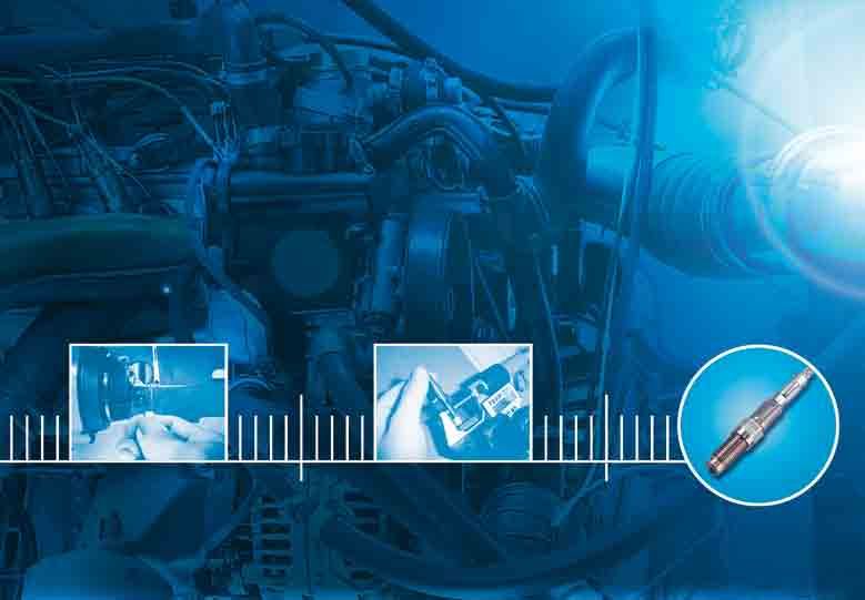
Contents

                  From Crystal to Sensor in 200 Steps                           4

                  Kistler Pressure Sensors – Varied and Innovative in Design    6

                  PiezoSmart® Means Automatic Sensor Identification             8

                  Pole Position in all Engines                                 10

                  Fundamentals of Combustion Analysis                          12

                  Systems for Combustion Analysis – KiBox® for In-Vehicle      14
                  Applications

                  System Integration on Test Stand                             16

                  Made to Measure Service Individualized to Suit Each Customer 18

                  Product Details and Range

                  Measuring Chains                                             20

                  Measuring                                                    24

                  Connecting                                                   43

                  Electronics & Software                                       46

                  Accessories                                                  55

                  Calibrating                                                  58

                  Technical Literature                                         61

                  Glossary                                                     62

                  Overview of Products in Order of Type Number                 64

www.kistler.com                                                                     3
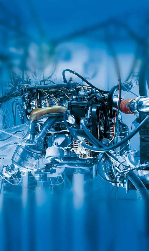
From Crystal to Sensor…
The manufacture of piezoelectric sen- At the core of a piezoelectric sensor is a PiezoStar® crystals are individually grown
sors has much in common with preci- crystal measuring element. Application of for combustion analysis
sion watchmaking. Sensor fabrication a mechanical force to this crystal gener- Kistler predominantly uses quartz (silicon
ates, on its surfaces, a proportional electric dioxide (SiO2)) as its crystal material.
requires meticulous accurate assembly of
charge that can be used as a measurement However, for sensors to be used under
individual parts, typically just a few mil- signal. Piezoelectric sensors are particularly extreme operating conditions, combustion
limeters in size, with up to 200 separate suitable for precise measurement of high- analysis for example, Kistler grows it's own
steps needed. These delicate manual speed phenomena over wide measuring crystals and has done for approximately
operations culminate in precision Kistler ranges and at high temperatures. 10 years. Known as PiezoStar crystal,
measuring equipment that has been sub- Kistler then produces customized measur-
ing elements with bespoke characteristics.
jected to 100 % quality control at various
stages. After all, these sensors have to
yield reliable, accurate measurements
over a long service life.
12
10 Polystable® quartz (1970)
X-cut quartz
Sensitivity [pC/N]
PiezoStar® KI100 (2002)
8 PiezoStar® KI85 (1990)
GaPO4*
6
4
2
0
0 100 200 300 400 500 600
Temperature [°C] *Not a Kistler crystal
For each application Kistler offers optimized sensor packages manufactured from
different crystal materials
4 www.kistler.com
...in 200 Steps
This enables the company to offer spe- 100 % quality control at each step Assembly under cleanroom conditions
cially optimized high-performance sensor The small measuring elements come in a The final assembly of the sensors amounts
packages with an extremely high level of wide variety of shapes and sizes and are to precision engineering. It is performed
accuracy and a long life. formed from the wafers in numerous, under a microscope in a class 5 cleanroom
mainly manual, intermediate steps. The environment. Here, precision and a steady
It all starts with an X-ray crystal elements are cut, lapped, coated hand are absolutely imperative as the
The orientation of the crystal lattice and re-lapped to the nearest micrometer. smallest flaw makes a sensor unusable.
relative to the surfaces of a measuring Kistler leaves nothing to chance. Therefore each individual step has to be
element is the determining factor in the described with strict assembly instructions.
properties of the element. To ascertain the After each step, the measuring elements Once the sensor has been completed, a
individual axes of the crystal and hence are cleaned and their dimensional ac- laser is used to mark it with a "K" repre-
the planes on which the measuring ele- curacy and surface finish is checked. The senting the brand, the type designation
ments are sliced, each crystal ingot is same applies to all of the other individual and the serial number. Final inspection
X-rayed before being processed. Only parts, such as the case, diaphragm, insula- then takes place before all of the data is
then is it sliced into thin wafers, an opera- tor, contact spring, connector and so on. saved under the sensor serial number in a
tion which takes up to 24 hours in itself. database.
www.kistler.com 5
Kistler Pressure Sensors…
The range of Kistler sensors reflects the Piezoresistive
multifaceted nature of engine develop-
Pressure Sensors
ment. Miniature piezoelectric pressure
sensors measure cylinder pressures
The piezoresistive principle is based on
extremely precisely as a basis for thermo- the semiconductor effect first described in
dynamic analysis of the combustion proc- 1954, which states that under mechanical
ess. Equally unique are the piezoresistive stress semiconductors change their electri-
sensors for very accurate measurement of cal resistance. Compared with the con-
intake and exhaust manifold pressures. ventional strain gage measurement of the
time, this opened up completely new ap-
plications. Since then similar breakthroughs
Piezoelectric have included the thin film technique on M8 cooled piezoelectric pressure sensor,
Pressure Sensors metal and its thick layer counterpart on Type 6041B…
ceramic.
The piezoelectric effect – the prefix
"piezo" comes from the Greek "piezein", Piezoresistive sensors from Kistler measure
to press – was discovered in 1880 by static pressures in gases and liquids. The re-
the Curie brothers. They found that the sults achieved under even the most adverse
surfaces of certain crystals – including conditions are precise and repeatable.
quartz – become electrically charged
when the crystal is mechanically loaded.
This electrical charge is exactly propor- Applications at a Glance
tional to the force acting on the crystal. It
is measured in picocoulombs (1 pC = 10–12 1. Precision measurement of cylinder
coulombs). pressures with cooled PiezoStar cyl-
inder pressure sensor for combustion M5 piezoelectric pressure sensor,
As active designs, piezoelectric sensors analysis, gas exchange analysis and Type 6052C…
can only be used for quasistatic rather combustion development
than truly static measurement. However
they are ideal for dynamic applications. 2. Measurement of cylinder pressures
Piezoelectric pressure sensors can be without additional mounting bore
employed wherever rapidly changing for the sensor.
pressures at temperatures of up to 400 Measuring spark plugs:
°C have to be measured as accurately as For knocking analysis and use in the
possible. vehicle
Glow plug adapters:
In addition to quartz, particularly for un- For measurement in DI diesel en-
cooled sensors, Kistler uses crystals gines. Also available as measuring
developed and grown in-house. These glow plugs for cold start measure-
PiezoStar ® crystals are characterized by ments M5 piezoresistive absolute pressure sensor, Type
high sensitivity and high thermal stability. 4005B…
3. Pressure indication with uncooled
piezoelectric PiezoStar sensors for
thermodynamic analysis and engine
calibration
For more information on the
4. Low-pressure indication in the intake topic of uncooled sensors,
and exhaust with piezoresistive pres- please refer to page 24.
sure sensors. Cooling or switching
adapters are used for this purpose in
the exhaust. Such instrumentation is For more information on
employed for gas exchange analysis the topic of cooled sensors,
and optimization please refer to page 30.
6 www.kistler.com
...Varied and Innovative in Design

A capacity for innovation, close contact       Simulation and Calculation                                       Cable
with the world's leading engine manu-
facturers and skilled application expertise    A wide operating temperature range,                              Coolant connection
                                               impressive thermal stability and a high
help explain why Kistler sets the pace for
                                               natural frequency represent the inherent
engine measurement. Kistler always             advantages of the piezoelectric measure-
offers the best solution for accurate pres-    ment for engine combustion pressures.
sure measurement over a wide spectrum          During operation in this difficult environ-
                                                                                                                Ceramic-insulated connection
of sectors from extremely high-precision       ment the sensors are subjected to signifi-
research to demanding racing applications.     cant thermal and mechanical influences
                                               and measures taken to minimize these
                                               effects often have aims that conflict in
Reliable Development                           many complex ways.
                                                                                                                Case

Partner for Research and                                                                                        Electrode
                                               To tackle this complexity and to identify
Industry                                       potential resolutions to their conflicts,
It achieves all this by drawing on an ex-      Kistler uses sophisticated calculations and
tensive range of products that comple-         simulation tools within the sensor devel-                        Crystal
ment piezoelectric and piezoresistive          opment process. Starting with a model that
sensors with matching signal conditioning      represents the geometric, mechanical and                         Temperature compensator
and a diverse selection of accessories.        thermal properties of a sensor, the effects
                                                                                                                ThermoComp® diaphragm
Such a comprehensive choice ensures, the       of a wide variety of factors on the measure-
perfect sensor package is coupled with the     ment results can be analyzed and described     Cooled sensor
ideal signal conditioning which can always     quickly and efficiently.
be used for the maximum accuracy in
each individual pressure indication project.

The modularity of Kistler sensors allows
for cost effective customization. This                                                                          Cable

further increases the benefits for the
customer by always ensuring accurate
measurements, even with special sensor
configurations or service conditions.

                                                                                                                Case

                                                                                                                Electrode

                                                                                                                Anti-strain

                                                                                                                Crystal

                                                                                                                ThermoComp® diaphragm

                                                                                              Uncooled sensor

FEM-model of a front sealing sensor

www.kistler.com                                                                                                                           7
PiezoSmart ... ®
Detailed planning, comprehensive con PiezoSmart is an active system for the Unambiguous assignment of sensor data
figuration of measuring chain parameters automatic identification of individual The core of PiezoSmart is the transducer
and precise assignment of measuring pressure sensors. Plug & Measure (auto- electronic data sheet (TEDS). Sensor data
matic configuration of measuring chain is saved in the TEDS, which takes the form
points – even the preparations for engine
parameters) reduces the risk of error and of a chip in the connector at the ampli-
pressure indication are enormously additional functions guarantee the quality fier end of the sensor cable. The connec-
involved. Production of the necessary of the pressure indication data. Two points tor and pressure sensor form an easily
documentation and related procedures is of particular importance to the end user mounted physical unit which ensures reli-
labor-intensive and error-prone. In combi- are that: able, clear-cut assignment of sensor data
nation with the signal conditioning plat- • PiezoSmart is suitable for all engine during test stand operation. Additional
pressure sensors and all existing cable system integrity is provided by a seal or
form (SCP), PiezoSmart automatic sensor
and connector combinations self-adhesive markings.
identification offers test stand operators • PiezoSmart modularity allows for the
enhanced process reliability, extensive upgrading of existing or used sensors
flexibility and improved data quality with with sensor identification
less preparation.
Automatic setting of sensitivity values
Optimum sensitivity value automatically set to suit utilized pressure
measuring range and defined temperature range
Kalibrierschein DRUCK
Calibration Certificate PRESSURE
Type 6052C Serial No. 1608400
Kalibriert durch Datum
Calibrated by Date
G. Ratano 21.05.2007
Referenzgeräte Typ Serien-Nr.
Reference Equipment Type Serial No.
Gebrauchsnormal
Working Standard Kistler 7005-350 492592
Ladungsverstärker
Charge Amplifier Kistler 5017B 1479195
Ladungskalibrator
Charge Calibrator Kistler 5395A 441991
Umgebungstemperatur Relative Feuchte
Ambient Temperature Relative Humidity
°C %
26 44
Messergebnisse Results of Measurement
Database
Kalibrierter Bereich Empfindlichkeit Linearität
Calibrated Range Sensitivity Linearity
bar pC / bar ? ± %FSO
0 ... 250 (23°C) -21,33 0,05
0 ... 150 (23°C) -21,37 0,08
0 ... 100 (23°C) -21,39 0,10
0 ... 50 (23°C) -21,42 0,07
0 ... 250 (200°C) -21,16 0,06
0 ... 150 (200°C) -21,19 0,09
0 ... 100 (200°C) -21,21 0,10
0 ... 50 (200°C) -21,23 0,08
0 ... 250 (350°C) -21,49 0,06
0 ... 150 (350°C) -21,54 0,09
0 ... 100 (350°C) -21,56 0,11
0 ... 50 (350°C) -21,56 0,18
Messverfahren Kontinuierliche Kalibrierung, Vergleichsverfahren
Measurement Procedure Continuous Calibration, Comparison Method
Bestätigung Confirmation
Die Geräte halten die Herstelltoleranzen gemäss Spezifikationen der Datenblätter ein. Wir bestätigen, dass das oben identifizierte Gerät nach
den vorgeschriebenen Verfahren geprüft wurde. Alle Messmittel sind auf nationale Normale rückverfolgbar. Kistler betreibt die SCS (Swiss
Calibration Service) Kalibrierstelle Nr. 049, akkreditiert nach ISO 17025. Das Kistler Qualitätsmanagement System ist nach ISO 9001
zertifiziert.
The equipment meets the manufacturing tolerances according to the specification data sheets. We confirm that the device identified above
was tested by the prescribed procedures. All measuring devices are traceable to national standards. The SCS (Swiss Calibration Service)
Calibration Laboratory No. 049 is operated by Kistler and accredited per ISO 17025. The Kistler Quality Management System is certificied
per ISO 9001.
Kistler Instrumente AG
Eulachstrasse 22 Tel. +41 52 224 11 11 ZKB Winterthur BC 732 IBAN: CH67 0070 0113 2003 7462 8
PO Box Fax +41 52 224 14 14 Swift: ZKBKCHZZ80A VAT: 229 713
CH-8408 Wintherthur info@kistler.com Account: 1132-0374.628 ISO 9001 certified www.kistler.com
Seite page 1 / 1
PiezoSmart® data memory
8 www.kistler.com
...Means Automatic Sensor Identification
The TEDS contains the serial number, Standalone operation Clear assignment of data to a sensor
initial and current calibration values of the Decentralized storage of sensor data The sensor and connecting cable with the
sensor, additional manufacturer and iden- means PiezoSmart permits independent TEDS form a physical unit, i.e. they are
tification data. Monitoring of the initial operation of the sensor and measuring permanently connected and do not need
and re-calibration values of the individual chain. Consequently, the system is ready to be disconnected even to mount the
sensors allows early detection of sensor for use at any time, a host database is not sensor.
anomalies. This in turn helps limit test necessary.
stand failures and the loss of data. The connection integrity is shown by the
Interfacing the sensor to the test stand presence of a seal. The individual parts are
The chips have hierarchical password- The signal conditioning platform (SCP) spot welded together in the factory and
protected access and are write protected provides the link between the sensor and supplied with this seal. After any upgrade,
to allow the user to make any necessary the test stand. As a flexible equipment the seal or a sticker with the "Kistler-K" at
sensor re-calibration or for the replace- platform, measuring modules are installed the line of the break shows that the con-
ment of faulty sensors and cables. to support particular test configurations nection is intact.
and sensor selection.
PR-low pressure
PE-cylinder pressure
Access authorization to TEDS data
Header:
– Kistler
– Sensor Type number PE-cylinder pressure
– Version letter
– Sensor version number
– Sensor serial number
Initial calibration:
– Number of temperature ranges
– Initial calibration date
– Initial calibration values
Examples of sensors with PiezoSmart®
Recalibration:
– Reference temperature
– Recalibration date Advantages at a Glance
– Recalibration values
• Automatic configuration of charge
Footer:
– Comments
and voltage amplifier parameters
User Calibration Manufacturer
• Accurate pressure indication data
read only read/write from simplified measurement
Hierarchical access and write authorization • Simple setup processes speed up read-
iness for measurement on test stand
• Easy evaluation and documenta-
tion of measurements through
automatic exchange of data
with evaluation systems
• High availability of pressure indi-
Sensor Seal Connecting cable PiezoSmart® coupling cation sensors ensured by multi
channel calibration systems
Unit with sensor, connecting cable and TEDS
For more information on the topic
of Upgrading, please refer to page
18.
www.kistler.com 9
Pole Position…

From pioneer to technological leader –                 The development of measuring instru-                    The breakthrough came in 1950 with the
Kistler has been involved in the develop-              mentation for engine improvement is                     grant of a patent for charge amplifiers – the
ment, manufacture and application of                   closely linked with the history of Kistler              devices that convert the signal of piezoelec-
                                                       as a company. It all began in 1944, when                tric sensors into a useful voltage. Just a few
piezoelectric sensors since 1950. The
                                                       the two subsequent founders of today's                  months later the PZ-14 piezoelectric pres-
company's sensors have played a key role               Kistler Instrumente AG, Hans-Conrad                     sure sensor, which formed the nucleus of
in the development of internal combus-                 Sonderegger and Walter P. Kistler, got to               many subsequent designs, was developed.
tion engines over this extended period.                know each other at SLM (Swiss locomo-
This striking success reflects their "inside           tive and machinery works) in Winterthur.                Kistler has been developing and producing
view" of the combustion chamber as the                 Sonderegger was responsible for develop-                piezoelectric pressure sensors since 1959.
                                                       ing a new air-cooled diesel engine and                  They are still delivering reliable results
only source of information needed to
                                                       Kistler for modern measurement methods.                 under even the most extreme conditions.
optimize combustion for better efficiency
and minimize harmful emissions.

                                                                                                               Marine engines

                                              1951                                                            1972

          1950                                                                  1961                                                     1989

                                                                                                                                              Kistler offers worlds
                                                                                                                                              first high-tempera-
                                                                                                                                              ture pressure sensor
                                                                                   Launch of high-pressure       First Polystable®            with M5 thread for
               Charge amplifier patent           First piezoelectric pressure      sensors, for pressure up      crystal sensor ,             engine measuring
               granted to Walter P. Kistler      sensor Type PZ-14                 to 1 500 bar                  ground isolated              instrumentation

10                                                                                                                                       www.kistler.com
...in all Engines
Motorbike engines Car engines
Locomotive engines Race engines
1992 2004 2010
1993 2007
First use of PiezoSmart®
sensors in engine measur-
First measuring glow plug ing instrumentation and
First water-cooled for pressure measure- M10 measuring spark Piezoelectric high- Smallest PE sensor
ThermoComp® sensor ment in diesel engines plug for racing temperature sensor Type 6054AR...
www.kistler.com 11Fundamentals of Combustion Analysis
Development and optimization of mod
Sources: Deutz AG
ern internal combustion engines is incon-
ceivable without the knowledge of what
is happening in the cylinders. Measure-
ment and analysis of the variation in
cylinder pressure is the only source of
the data needed to optimize efficiency,
engine output, emissions and last but
not least engine life. The better the data
the more valuable the information that is
derived.
Reciprocating piston internal combus-
tion engines are basically heat engines in
that they essentially convert the chemi-
cal energy from the air/fuel mixture into
mechanical work and heat by means of
combustion. Indicator pV diagram recorded by Nikolaus Otto in 1876
Based on this knowledge, Nikolaus Otto
Mech. Work
and Rudolf Diesel pioneered the use of
indicators allowing simultaneous record
Fuel
ing of combustion chamber pressure and
Heat
piston position.
Exhaust
In the German-speaking world "indica-
tion" currently refers to all work related to
Conversion of chemical energy from fuel into me-
analysis of the pressure curve in combus-
chanical work and heat tion engines. Depending on the applica-
tion, rather than being limited to the
actual combustion this now covers gas
Developers aim to extract from the con- exchange, injection system, ignition sys-
© 2006 by AUCTION TEAM BREKER, Köln/Germany
version as high a proportion of mechanical tem, etc. English-speaking regions mainly
work as possible, that is to maximize ef- talk about "combustion analysis".
ficiency. The magnitude and variation with
time of the cylinder pressure acting on the Combustion analysis or engine pressure
piston are significant in this respect. This indication is regarded as a basic tool in
pressure curve represents the combustion engine development and is the key to
and hence the way in which the energy
conversion takes place in the engine. • improving efficiency
Consequently, the total mechanical work • increasing engine output
on the piston over a cycle is a function of • reducing emissions
the pressure and the associated change in • prolonging engine life
combustion chamber volume.
Otto engine of 1870
12 www.kistler.comCylinder Pressure Analysis P
Gas Exchange Analysis
For most applications combustion analysis Gas exchange analysis is used to evalu-
Cylinder pressure
data is shown relative to top dead center ate and optimize filling of an individual
(TDC) of the power stroke or to a particu- cylinder: the better the filling, the higher
lar combustion cycle. The most important the achievable cylinder output. However,
source of information in indication is the fuel consumption and emission character-
cylinder pressure curve. Both the signal istics can also be optimized with the aid of
level and the variation relative to the posi- Crank angle the data provided. This can be important
Top dead center
tion of TDC are important in this regard. if the engine developer wants to employ
Cylinder pressure curve over cycle of 4-stroke diesel a variable valve train to influence the gas
engine exchange in a flexible manner, or wishes
to modify the induction process with a
variable intake manifold, etc.
In all application sectors engines and
combustion systems have reached a level
Kistler Know How of complexity that could not be mastered
without pressure indication measurement.
The data calculated from cylinder pressure signals and resultant information includes: For research, development and the tuning
of engines, pressure indication provides
Derived data Information provided on the only basis for complying with emission
legislation and meeting performance and
Peak pressure Mechanical load on drivetrain
consumption expectations.
Indicated mean effective pressure, Cylinder output
complete 4-stroke cycle or Combustion stability
high-pressure component only (cyclical fluctuations) Intake Exhaust
Misfiring
Response
Friction losses
High-frequency component of vibration Knocking
Pressure gradient Combustion noise
Crank angle at peak pressure Overall efficiency
Schematic of
Heating curve and energy Combustion efficiency
measuring points
conversion points Qualitative exhaust values for gas exchange
Quality of ignition system analysis
Gas temperature Qualitative exhaust values
Low-pressure component of the indicated Gas exchange losses 2.0
Cylinder pressure
mean effective pressure, pV diagram
Pressure (bar)
Combustion curve Energy balance 1.5
Mass flow rate Filling of cylinder Exhaust
Residual exhaust gas in cylinder Intake
1.0
Backflow
Gas exchange losses
Ignition delay, calculated from Formation of air/fuel mixture 0.5
0 90 180 270 360 450 540 630 720
ignition or injection point and Crank angle (degrees)
start of combustion
Pressure curves in intake manifold, cylinder and ex-
haust manifold. In the interest of clarity the compres-
sion and combustion pressure of the measured curves
are truncated at 2 bar
www.kistler.com 13Systems for Combustion Analysis...
Measuring
Kistler PiezoStar® crystals provide the accessories these sensors produce readings
foundation for an optimized sensor design that deliver the very best possible results.
providing precision measurements from a To analyze gas exchange, Kistler offers
miniature device. Combined with engine- absolute pressure sensors based on the
specific adapters and the appropriate piezoresistive measuring principle.
Amplifying
High-performance measurement ampli- The "PiezoSmart®" automatic sensor
fiers convert the raw pressure signal into identification system is based on the TEDS
a precision-scaled voltage which forms (Transducer Electronic Data Sheet) proto-
the interface between sensor signal and col. This system automatically configures
measuring system in the tried-and-tested all cylinder and low pressure amplifiers
Signal Conditioning Platform (SCP). and records the operating time, ensuring
a high level of flexibility, data quality and
process reliability.
14 www.kistler.com...KiBox® for In-Vehicle Applications
The development, production and to precisely measure and record extremely the results is determined not only by the
practical application of piezoelectric dynamic pressure conditions in cylinders sensor properties alone but also by an
sensors and amplifiers has been Kistler’s led to high levels of efficiency and lower application-specific measuring chain that
core business since the 1950s. Even then emission values common in modern includes connecting cables, amplifiers
our technology was being used in the engines. For over ten years we have been and an evaluation system. Our range of
research and development of internal growing piezoelectric crystals in-house, combustion analysis products is the result
combustion engines, both industrial and specifically for use in combustion pres- of decades of intensive collaboration with
automotive. The ability sure sensors. However, the precision of our customers.
range a combustion analysis system de-
signed specifically for in-vehicle use. Stand-
ardized interfaces, powerful PC technology
Analysis and the option to use the proven SCP am-
Working in close collaboration with users, combustion development and automo- plifier modules ensure that the customer’s
Kistler has taken a significant step in pro- tive calibration engineers the information investment is both well protected and well
viding a development tool that will improve they need to perform their everyday tasks utilized. The same factors also mean that
the quality of data and help to reduce the is to analyze the measured signals and the the user has a tool that is easy to use and
overall development time for new vehicles. resultant parameters. By developing the can deliver extremely precise results after a
Kistler realized that the only way to give KiBox, Kistler has now added to its product very short set-up period.
www.kistler.com 15System Integration on Test Stand
Sensors, cables, charge amplifiers and the
signal conditioning system from Kistler can
be readily configured for different combus-
tion analysis tasks. Standardized interfaces
ensure that the signal processing system 2
is compatible with a wide variety of test
configurations and test stand environ-
ments. The PiezoSmart automatic sensor
1
identification system ensures the seamless
exchange of data between sensor and eval-
uation electronics. This meets the essential
requirements for quick and easy evaluation
and analysis of measurement data.
Accessories 1 Measuring 2 Connection
Crank angle encoder Combustion pressure Low-impedance cables
TDC sensor Intake/exhaust High-impedance cables
Cooling unit Injection pressure Oil-resistant cables
Torque
16 www.kistler.com3
4
3 Amplification/Conditioning 4 Acquisition/Analysis
1.2
1.1 Meas. Sparking Plug
Thermodyn. Loss Angle [°CA BTDC]
Reference Sensor
1.0
0.9
0.8
0.7
0.6
0.5
0.4 65
0 1000 2000 3000 4000 5000 6000
Meas. Sparking Plug
55
SCP Speed [1/min]
Reference Sensor
45
dQ [kJ/m 3°CA]
35
25
15
5
-5
-90 -60 -30 0 30 60 90 120
Crank Angle [°CA]
Signal preparation in the signal condi PiezoSmart allows automatic configuration The high-precision sensor system in com-
tioning platform (SCP), an integrated of measuring chain parameters for greater bination with accurate signal conditioning
equipment platform with measuring func- process reliability and automatic record- makes even the smallest changes in pres-
tion modules. ing of sensor operating time and pressure sure available for analysis.
cycles.
Kistler SCP and PiezoSmart® Pressure indication system A
Commands (measure, DriftComp)
Pressure indication system B
Read (calibration factors) Standardized interface
Write (operating time, ranges)
Microsoft® COM standard
Configuration (parapeters) Pressure indication system C
Pressure indication system ...
www.kistler.com 17Made to Measure Service...
Kistler's broad range of support services Training and Information Advantages at a Glance
extend from application engineering, on-
Kister augments the selection of serv- • Customized versions of sensors
site calibration through to the develop-
ices on offer by disseminating specialist • Upgrading with PiezoSmart
ment of customized sensors. Additional
knowledge and expertise in the form of sensor identification
resources are dedicated to providing high presentations and papers at conferences,
quality sensors and customer oriented symposia, exhibitions and trade shows. • Factory and on-site calibration service
training courses. In addition, regular basic and advanced • Standards for calibrating sensors
training seminars are held for customers
covering topics related to measurement • Basic and advanced
From choosing the right sensor through and combustion. customer training seminars
to correct mounting, Kistler's Application • Installation and process
Engineering personnel support and advise This range of services also includes the instructions for sensors
the customer as required on all questions availability of an extensive library of refer-
relating to engine pressure indication. The ence material in either hard-copy or elec- • Literature and information leaflets
aim is to ensure that the measurement tronic form with data sheets, brochures, for specific applications
is always performed with the technol- manuals and application papers being the
ogy yielding the maximum benefit and most popular.
of course, to ensure a sensor operates at
maximum accuracy over a long service
life.
Adding PiezoSmart®
Sensor Identification
The modularity of the sensors allows both
user or factory upgrading to PiezoSmart.
Depending on the required configuration
a Triax connector or coupler can be added
to an existing sensor or, if necessary, the
entire cable assembly can be replaced with
a PiezoSmart cable. This ensures that the
user can integrate existing sensors into
a new test stand and quality assurance
procedures.
Data stored for sensor
serial number xxxx
For more information on the
topic of PiezoSmart®, please
refer to page 8 or to PiezoSmart®
System Description Doc. No.
100-421.
18 www.kistler.com...Individualized to Suit Each Customer
Calibration Service
The Calibration Service always operates
under strict adherence to all relevant qual-
ity assurance and procedural guidelines.
Naturally this includes comprehensive
documentation and archiving to ensure
traceability and continuity of sensor cali-
brations.
If operational requirements or cost re-
stricts the transportation of sensors and
equipment to Kistler, then Kistler can bring
the calibration service to the customer.
The calibration can be performed quickly
and cost effectively in-situ with semi and
fully automatic calibration equipment.
For more information on the topic Various pressure generators, reference sensors and charge calibrators are available for calibrating the sensors and
charge amplifiers
of calibration, please refer to page
58 onwards.
Customized Sensors
The Kistler range encompasses well
over 1 000 different pressure sensors Measuring spark plug
for engine pressure indication, provid-
ing a suitable sensor package for virtu-
ally any task.
There are cases however, where
particular testing requires either an
improved performance or where a
customized sensor is needed to opti-
mize the total test package. In these
situations Kistler develops with the
customer an individualized version,
which, thanks to the modularity of the
sensors and wealth of different adapt-
ers, cable and connector combina-
tions, can generally be manufactured Glow plug adapters for develop- Oil-resistant connectors and cable connec-
at a reasonable cost. ing diesel engines tions for routing cable in cylinder head
www.kistler.com 19Measuring
High-pressure Sensors for Measuring Cylinder Pressure
Type Mounting Mounting Design Pressure Temp. range
thread diameter range min./max.
PiezoSmart® sensor identification available
6474A... mounting nut (3/8"x24 UNF)
6473A... mounting nut (M10x1)
6472Asp mounting sleeve
Measuring spark plug
Uncooled
Cooled
Sensor
Sensor Probe
6052C... M5x0,5 4,4 mm ( ) 0 ... 250/... 300 bar* –20 ... 350 °C
6053CC... M5x0,5 4,4 mm ( ) 0 ... 250/... 300 bar* –20 ... 350 °C
6054AR... M5x0,5 4,4 mm ( ) 0 ... 300 bar –20 ... 350 °C
6055C... M5x0,5 4,4 mm ( ) 0 ... 250/... 300 bar* –20 ... 350 °C
6056A... M5x0,5 4,4 mm ( ) 0 ... 250/... 300 bar* –20 ... 350 °C
6058A M5x0,5 4,0 mm ( ) 0 ... 250 bar –20 ... 350 °C
6041B M8x0,75 11,5 mm ( ) 0 ... 250 bar –20 ... 350 °C
6043A... M8x0,75 9,8 mm ( ) 0 ... 250/... 300 bar* –20 ... 350 °C
6061B... M10x1 13,5 mm ( ) 0 ... 250/... 300 bar* –20 ... 350 °C
Mounted 9,9/ ( )
6067C... 0 ... 250/... 300 bar* –20 ... 350 °C
in sleeve 12,6 mm
7061B... M14x1,25 16 mm ( ) 0 ... 250 bar –20 ... 350 °C
6045A... M8x0,75 9,8 mm ( ) 0 ... 250/... 300 bar* –20 ... 350 °C
6081A... M5x0,5 4,0 mm ( ) 0 ... 250 bar –20 ... 200 °C
6125C... M10x1, 3/8"x24 UNF 6,2/8,5 mm ( ) 0 ... 300 bar* –20 ... 350 °C
6113B... M10x1 ( ) 0 ... 200 bar –20 ... 200 °C
6115B... M12x1,25 ( ) 0 ... 200 bar –20 ... 200 °C
6117B... M14x1,25 ( ) 0 ... 200 bar –20 ... 200 °C
6118B... M14x1,25 ( ) 0 ... 200 bar –20 ... 200 °C
*...U20 version (with reinforced diaphragm) ** Assortment of common adapters, connecting cables and couplers
20 www.kistler.com6525Asp... mounting sleeve
6542Q... glow plug adapter
6544Q... glow plug adapter
6442 dummy sensor for Type 6061
6444 dummy sensor for Type 6067
Mechanical
6445 dummy sensor for Type 6052
6469 dummy sensor for Type 6125
www.kistler.com
6475 dummy sensor for Type 6041
6477 dummy sensor for Type 6045
7441 dummy sensor for Type 7061
1631C... (KIAG 10-32 pos. – BNC pos.)
1635C... (KIAG 10-32 pos. – KIAG 10-32 pos.)
1919A1 (M4 pos. integral – KIAG 10-32 pos.)
1927A1 (M4 pos. integral – KIAG 10-32 pos. integral)
1929A1 (M4 pos. integral – M4 pos. integral)
1957A1 (KIAG 10-32 pos. – KIAG 10-32 pos.)
adapter**
1967A1 (KIAG 10-32 pos. integral – KIAG 10-32 pos. integral)
1969A1 (KIAG 10-32 pos. integral –
KIAG 10-32 pos. integral)
Connecting cable**
1983AC1 (KIAG 10-32 pos. integral – KIAG 10-32 pos. integral)
1989A... (M3 pos. – ...) with sensor/probe integral
1989A415U43 (M3 pos. – KIAG 10-32 pos. integral)
with sensor/probe integral
1705 (M4 neg. – BNC pos.)
1706 (M3 neg. – BNC pos.)
Coupler
1721 (KIAG 10-32 neg. – BNC pos.)
charge
amplifier
5018A...
laboratory
**
SCP
Amplifier
charge
amplifier
5064B21
SCP
sensor
charge
5064B22
PiezoSmart-
identification
amplifier with
More
Page 34
Page 34
Page 34
Page 34
Page 28
Page 28
Page 28
Page 32
Page 32
Page 30
Page 30
Page 30
Page 26
Page 26
Page 24
Page 24
Page 24
Page 24
Inform.
21
when using PiezoSmart® sensorsMeasuring
Low-pressure Sensors for Intake/Exhaust Measurement
Type Mounting Measuring range Temperature range Sensor version Mechanical Cooling
thread (absolute) min./max. adapter
7533A... switching adapter M14x1,25
In the printed ver-
sion the measuring
range (absolute)
6596 adapter M14x1,25
7501 adapter M14x1,25
Type 4005B... and
6598 adapter M12x1
7525A... M14x1,25
Type 4007B... have
7503 adapter M5
been mixed up.
PiezoSmart
In this PDF the
Standard
values are displayed
correctly.
Sensor
4005B... 0 ... 2/... 5/... 10/ 4005BA...
M5x0,5 ... 20/... 50/... 100/ –40 ... 125 °C
... 200/... 400 bar 4005B...V200S
4007B... 4007BA...
M5x0,5 0 ... 5/... 250 bar –40 ... 200 °C
4007B...S
4043A... 4043A...
M14x1,25 0 ... 1/... 500 bar –40 ... 70 °C
4043A...V200S
4045A... 4045A...
M14x1,25 0 ... 1/... 500 bar 0 ... 140 °C
4045A...V200S
4073A... 4073A...
M12x1 0 ... 10/... 500 bar –40 ... 70 °C
4073A...V200S
4075A... 4075A...
M12x1 0 ... 10/... 500 bar 0 ... 140 °C
4075A...V200S
4049A...
0 ... 1 100 °C
M14x1,25 0 ...5/...10 bar 4049A...S
(water cooled)
High-pressure Sensors for Injection
Type Mounting Measuring range Temp. range Sensor version Clamp adapter
thread Design (absolute) min./max.
6533A28 (cable >8 ... 13 mm)
6533A18 (cable 6 ... 8 mm)
6533A11 (cable 6 mm)
6533A21 (cable 6 mm)
6533A28 (cable 8 mm)
Measuring chain
6533A12 (cable ¼“)
6533A22 (cable ¼")
piezoresistive
piezoelectric
PiezoSmart
Standard
Sensor
Sensor
4065A...
4065A...
M7x0,75 0 ... 200/... 1 000 bar 0 ... 120 °C
4065A...S
4067...
4067...
M10x1 0 ...1 000/... 5 000 bar 0 ... 120 °C
4067...S
6229A... 0 ... 5 000 bar
M10x1 kalibrierter Teilbereich
0 ... 500 bar
–20 ... 200 °C 6229A...
22 www.kistler.com6533A19 (cable 8 ... 13 mm) 7511 M14x1,25
6533A110 (cable 13 ... 20 mm) 7507 M14x1,25
adapter
6919 adapter for 6906 pressure gen. 7505 M18x1,5
6925 adapter for 6906 pressure gen. Cable at sensor with length of 2 m
4155 adapter M14x1,25 Cable at sensor with length of 0,5 m
6503 adapter M10x1 4751A...Measuring
Piezoelectric Sensors
PiezoStar Miniature Sensors and Measuring Probes
M5 sensor M5 sensor M5 measuring probe 4,4 mm measuring probe
M5 thread set back
M5x0,5
L
M5x0,5 M5x0,5 M5x0,5
L L L
D D D D
Technical data Type 6052C... Type 6054AR... Type 6053CC... Type 6055C...
Measuring range bar 0 ... 250/... 300* 0 ... 300 0 ... 250/... 300* 0 ... 250/... 300*
Sensitivity pC/bar ≈–20/ ≈–19* –14 –20 –20
Natural frequency kHz ≈160 ≈160 ≈160 ≈160
Linearity %FSO ≤±0,3/≤±0,5* ≤±0,3 ≤±0,4 ≤±0,4
Temperature range °C –20 ... 350 –20 ... 350 –20 ... 350 –20 ... 350
Sensitivity change
200 °C ±50 °C % ≤±0,5 ≤±0,5 ≤±0,5Measuring
Piezoelectric Sensors
Sleeve Mounting Direct Mounting
Type 6052C... Type 6053CC...
ø13,5/SW 12
0,03
0,01
2
-0,052
ø6
-0,0
ø10 H7
ø6
8
ø10 G6
Mounting sleeve
0,5
Type 6525Asp 20 ... 50
Type 6525Asp 50 ... 200
M5x
X = 20 ... 200
ø9,5
ø10
Sensor
Type 6052C1
-0,02
Tightening torque of sensor
0
7
for Typ 6525Asp: 4 ... 7 N·m
4,4
M7 x0,75
Mounting Examples Utilizing M5 Sensors
Uncooled miniature sensors featuring M5
mounting threads are ideal for multi-valve
O-Ring O-Ring
engines with small combustion chambers. The
most effective heat dissipation is achieved
by mounting with front sealing, either within
a mounting sleeve or directly in the cylinder
head.
ø10 ø6
Types 6053CC... and 6055C... can be used
without an additional mounting sleeve in
6053
6052
water-cooled engines. Type 6054AR... is
6052 particularly well suited for high speeds, as it
6055 is less sensitive to vibration.
ø7,5
O-Ring ø3
M5 x 0,5
5
M7 x 0,7
M5 x0,5
ø4,5
M5 x
0,5
www.kistler.com 25Measuring
Piezoelectric Sensors
Miniature Sensors and Measuring Probes
4,4 mm measuring probe 4 mm measuring probe
standard length PiezoStar® standard length PiezoStar®
M5x0,5 M5x0,5
L L
D D
Technical data Type 6056A... Type 6058A...
Measuring range bar 0 ... 250/... 300* 0 ... 250
Sensitivity pC/bar –20 –17
Natural frequency kHz ≈160 ≈160
Linearity %FSO ≤±0,3 ≤±0,3
Temperature range °C –20 ... 350 –20 ... 350
Sensitivity change
200 °C ±50 °C % ≤±0,5 ≤±0,5
23 ... 350 °C % ≤±2 ≤±2
Thermal shock error
at 9 bar pmi (1 500 1/min)
∆ p (short term) bar ≤±0,5 ≤±0,5
∆ pmi % ≤±2 ≤±2
∆ pmax % ≤±1 ≤±1
Dimensions D mm 4,4 4
L mm 33,5 33,5
Characteristics As for Type 6052C... . Thread Probe with thread set back,
set back, M3 cable connec- M3 cable connection. Only
tion. Only requires 4,5 mm requires 4,1 mm mounting
mounting hole. Suitable for hole. Suitable for measure-
measurements with glow ments with glow plug adapter
plug adapter Type 6542Q... Type 6544Q... from 4,5 mm
from 5 mm diameter. Direct diameter. Direct mounting in
mounting in confined spaces. confined spaces.
Data sheet 6056A_000-529 6058A_000-573
Mounting bore ø5,7/≥7,5
ø5,7/≥7,5
M5x0,5 M5x0,5
10
A
8
ø4,5 +0,03
0
ø4,1+0,05
0
24
24
R
m
max. 0,1x45°
*2,5 4
,2
ax
ø3
R0
max. 0,1x45°
.0
ø3
x.
,2
ma
2,5 ... 4
*...U20 version (with reinforced diaphragm)
26 www.kistler.comMeasuring
Mounting in Glow Plug Adapters
Type 6056A... Type 6058A... Type 6056A...
in adapter Type 6542Q... in adapter Type 6544Q... in adapter Type 6542Q...
min.
4,6 mm
min.
5 mmMeasuring
Piezoelectric Sensors
Miniature Sensors
M8 sensor PiezoStar® 4 mm measuring probe Ground isolated PiezoStar®
M5x0,5
L
D
M8x0,75 L
L
D
D
Technical data Type 6045A... Type 6081A... Type 6125C...
Measuring range bar 0 ... 250/300* 0 ... 250 0 ... 300*
Sensitivity pC/bar –45 –9,5 –37
Natural frequency kHz ≈80 ≈120 ≈75
Linearity %FSO ≤±0,4 ≤±0,5 ≤±0,4
Temperature range °C –20 ... 350 –20 ... 200 –20 ... 350
Sensitivity change
250 °C ±100 °C % ≤±0,7 ≤±1 (200 ±50 °C) ≤±1
23 ... 350 °C % ≤±2 ≤±2 (23 ... 200 °C) ≤±2
Thermal shock error
at 9 bar pmi (1 500 1/min)
∆ p (short term) bar ≤±0,3 ≤±0,8 ≤±0,3
∆ pmi % ≤±1,5 ≤±4 ≤±1,5
∆ pmax % ≤±1 ≤±2 ≤±1
Dimensions D mm 9,8 4 6,2
L mm 7,9 30 ... 80 (available) 10
Characteristics High-temperature sensor, Miniature sensor for pres- High-temperature sensor with
non-cooled, shoulder-sealing, sure measurements, easily special mounting sleeve.
mounting bore M8x0,75, installed and robust, available Ground isolation allows inter-
mounting dimensions compa- in different lengths, 90° taper ference-free measurement
tible with Type 6041A..., high for flexible mounting. even where potential differ-
sensitivity, low thermal sensi- ences arise. Low thermal
tivity drift, long life, very low sensitivity drift. Very low
thermal shock error. thermal shock error with high
sensitivity.
Data sheet 6045A_000-618 6081A_000-494 6125C_000-695
Mounting bore
min. ø10
ø10
min. ø7,5 min. ø13
5 8,2
M10x1
7
12
8
M5x0,5 KIAG 3/8 ... 24
13
15
min. 37
max.
27
L
ø3 ø8,5
ø4,1
M8x0,75 ø6,35
2
*...U20 version (with reinforced diaphragm)
28 www.kistler.comMeasuring
Mounting Examples Thermal Shock
Type 6081A... Thermal shock, which is also called short-term
drift, is a measuring error arising periodically
within each combustion cycle. It is caused by
min. 8 time-dependent thermal stresses in the sensor dia-
4
phragm induced by the heat flux of hot combus-
tion gases, which can reach temperatures of over
Type 6081A30
2 000 °C for a few milliseconds.
M5x0,5 30
ø4,1
FEM simulation shows on a highly magnified scale
deformation of the diaphragm (left) under the influ-
ence of heat flux
ø2 The deformation of the diaphragm creates the
illusion of a change in pressure. The degree of
falsification of the measurement result depends
on the sensor, its mounting arrangement and the
operating point of the engine. Thus, in a given
Mounting Examples engine the error depends on the injection/ignition
point, speed, load, etc.
Type 6125C...
The magnitude of thermal shock is measured
relative to a water-cooled reference pressure sen-
sor whose low temperature error makes it ideal
with mounting sleeve
for precision thermodynamic measurements. The
O-ring O-ring thermal shock corresponds to the maximum devia-
tion between the unit under test and the reference
with mounting nut sensor. The values relate to measurements in a test
engine at 1 500 1/min and at an IMEP of 9 bar.
M10
x1
ø15
Type 6125
Type 6125
Type 6125
ø13
direct mounting
ø6,35
1
M10 x
ø6,35 Short-term drift of miniature sensor measured on
Kistler test engine
www.kistler.com 29Measuring
Piezoelectric Sensors
Sensors and Probes, Water-cooled
M8 sensor M8 probe M10 ThermoComp®
ThermoComp® ThermoComp® quartz pressure sensor
D
D
M8x0,75 M10x1
L M8x0,75 L
L
D
Technical data Type 6041B... Type 6043A... Type 6061B...
Measuring range bar 0 ... 250 0 ... 250/... 300* 0 ... 250/... 300*
Sensitivity pC/bar –40 –20 –25
Natural frequency kHz ≈70 ≈70 ≈90
Linearity %FSO ≤±0,3 ≤±0,5 ≤±0,5
Temperature range °C –20 ... 350 –20 ... 350 –20 ... 350
Sensitivity change
50 °C ±35 °C (cooled) % ≤±0,5 ≤±0,5 ≤±0,5
23 ... 350 °C (uncooled) % ≤±2 ≤±2 ≤±2,5
Thermal shock error
at 9 bar pmi (1 500 1/min)
∆ p (short term) bar ≤±0,25 ≤±0,25 ≤±0,2
∆ pmi % ≤±1 ≤±2 ≤±1
∆ pmax % ≤±1 ≤±1 ≤±1
Dimensions D mm 11,5 9,8 13,5
L mm 7,9 8 10
Characteristics Smallest water-cooled sensor Probe for direct mounting Water cooled sensor with
with M8 thread, excellent in 10,0 mm hole. Excellent M10 thread, excellent thermal
thermal drift stability due thermal drift stability due drift stability due to water
to water cooling. Double to water cooling. Double cooling. Double diaphragm
diaphragm with optimized diaphragm with optimized with optimized thermal shock
thermal shock resistance, long thermal shock resistance, resistance, long life due to TiN
life steel-sheathed cable. long life due to TiN coating coating and steel-sheathed
and steel-sheathed cable. cable.
Data sheet 6041B_000-516 6043A_000-014 6061B_000-020
Mounting bore
ø10
60°
min. ø12 min. ø14
min. 8,5
1
L
5 8,2
7
5 10,5
8
10
8,2
7
8
max.
max.
ø3 max. 5
M8x0,75 ø3 ø3 ... 5
M8x0,75 M10x1
*...U20 version (with reinforced diaphragm)
30 www.kistler.comMeasuring
Mounting Examples
Type 6043
Type 6041
ø10
ø1
4
ø12
ø10
Type 6041
M
12
Type 6043 x1
M8x0,75
M8 x
0,75
M8 x
0,75
Tips for Care of Cylinder Pressure Sensors
Quartz cylinder pressure sensors must be cleaned 3. Thorough cleaning in ultrasonic bath
at regular intervals depending on the type of ap- If necessary, a thorough cleaning of the sensors can
plication, service period and fuel being used. Any be achieved using an ultrasonic bath, however it is
deposits can be removed as specified in the follow- imperative to ensure:
ing instructions.
• The connecting cable is properly tightened
Note: The cable must be left connected to the sen- • The sensor is immersed in the cleaning agent up
sor during cleaning or a cap Type 1895… fitted to to its seal ring only
the sensor connector. • The cleaning time does not exceed 2 minutes
1. Rough cleaning Note: Cleaning for too long and use of excessively
Remove the layer of dirt (consisting of fuel resi- powerful ultrasonic baths can irreparably damage
dues, soot and lubricating oil) deposited on the dia- the sensor.
phragm with a mild abrasive agent (such as Kistler
polishing rubber (grade 240), Type No. 6.970.010).
Note: Never clean the front of the sensor with me-
tallic agents (for example, by brushing, grinding,
scraping or sand blasting), as this can irreparably
damage the diaphragm and hence the sensor.
2. Thorough cleaning
We recommend dipping the sensor in a cleaning
agent based on a mineral oil (e.g. petroleum ether,
petrol), cleaned with a brush and then dried with
compressed air. Kistler's Type 1003 cleaning spray
may be used for this task.
www.kistler.com 31Measuring
Piezoelectric Sensors
Sensors, Water-cooled
ø10 mm ThermoComp® M14 ThermoComp®
pluggable pressure sensor quartz pressure sensor
D
L M14x1,25
L
D
Technical data Type 6067C... Type 7061B...
Measuring range bar 0 ... 250/... 300* 0 ... 250
Sensitivity pC/bar –25 –80
Natural frequency kHz ≈90 ≈45
Linearity %FSO ≤±0,3 ≤±0,5
Temperature range °C –20 ... 350 –20 ... 350
Sensitivity change
50 °C ±35 °C (cooled) % ≤±0,5 ≤±0,5
23 ... 350 °C (uncooled) % ≤±2 ≤±2
Thermo shock error
at 9 bar pmi (1 500 1/min)
∆ p (short term) bar ≤±0,2 ≤±0,1
∆ pmi % ≤±1 ≤±0,5
∆ pmax % ≤±1 ≤±0,5
Dimensions D mm 9,9 16
L mm 9,5 13
Characteristics As Type 6061B... . Water-cooled sensor with
Special mounting sleeve for M14 thread, extremely high
easy mounting and removal sensitivity, excellent thermal
of sensor. drift stability due to water
cooling. Double diaphragm
with optimized thermal shock
resistance, long life due to TiN
coating and steel-sheathed
cable. Reference sensor.
Data sheet 6067C_000-021 7061B_000-052
Mounting bore
M14x1
min. ø18
15
min. 12
L
ø13
13,5
13
10,5
10
max.
5
ø3 ... 5 ø3 ... 5
ø10 M14x1,25
*...U20 version (with reinforced diaphragm)
32 www.kistler.comMeasuring
Sleeve
Type 6067C...
1203Bsp
max. 4
20
1
M14 min.
x1 hex 16
15
ø12,6
. 150
6471sp70 ... 150
70 ..
Option
18
Accessories for Mounting Sensors
The method of mounting the sensor heavily influences Kistler offers an extensive range of tools for forming the
measurement quality and sensor life. It is therefore very bores and threads, installing the sensors and finishing the
important to strictly follow the various tolerances and sur- sealing surfaces. Careful preparation using the correct
face finish requirements for the indicating bores in addi- tools and adapters will ensure a high quality of data and
tion to the torque wrench settings for tightening the the longest sensor life.
sensors.
ø18,5
M5x0,5
SW 5,5
ø7,3
ø9
ø4,5
ø5,5
SW 8
5
87
220
163
Mounting wrench SW 5,5 Type 1300A9 Finishing tool for bore Type 1300A79
ø7,5 h8
ø4,5 h8
SW 8
ø3
ø12
M5x0,5
6
4
2
N·m
4,4
5
3
10
222 19
175
10
3,5
Torque wrench 1 ... 6 N∙m Type 1300A17 Step drill Type 1300A51 ø6,1
26
SW 5,5
M5x0,5
10
ø5
SW 4
11
M4
M4
16
250
130
Dummy sensor Type 6445
Extraction tool for dummy sensor Type 1319 Special tap M5x0,5 Type 1357A (for Type 6052...)
www.kistler.com 33Measuring
Measuring Spark Plugs
M10x1 with integral M12x1,25 with integral M14x1,25 with integral M14x1,25 with integral
cylinder pressure sensor cylinder pressure sensor cylinder pressure sensor cylinder pressure sensor
M12x1,25
L M14x1,25
M10x1 M14x1,25 L
L L
Technical data Type 6113B... Type 6115B... Type 6117B... Type 6118B...
Measuring range bar 0 ... 200 0 ... 200 0 ... 200 0 ... 200
Sensitivity pC/bar –10 –10 –15 –10
Natural frequency kHz ≈130 ≈130 ≈130 ≈130
Linearity %FSO ≤±0,5 ≤±0,5 ≤±0,5 ≤±0,5
Temp. range (sensor) °C –20 ... 200 –20 ... 200 –20 ... 200 –20 ... 200
Sensitivity change
200 °C ±50 °C % ≤±0,5 ≤±0,5 ≤±0,5 ≤±0,5
Thermal shock error
at 9 bar pmi (1 500 1/min)
∆ p (short term) bar ≤±0,6 ≤±0,6 ≤±0,6 ≤±0,6
∆ pmi % ≤±3 ≤±3 ≤±3 ≤±3
∆ pmax % ≤±1,5 ≤±1,5 ≤±1,5 ≤±1,5
Dimensions
Sealing flat L mm 19/22/26,5 19/26,5 19/22/26,5 19/26,5
Sealing tapered L mm – – 17,5/23,5/25,4 –
Characteristics M10 measuring spark plug M12 measuring spark plug M14 measuring spark plug M14 measuring spark plug
with integral sensor. High with integral sensor. High with integral sensor. High with integral sensor. High
natural frequency, front natural frequency, front of sensitivity and natural natural frequency, front of
of sensor flush, replace- sensor flush, wide range frequency, front of sensor sensor flush, virtually concen-
able ceramic insulator, with of spark plugs available. flush. Replaceable cable. tric, replaceable ceramic
platinum electrodes. Reduced Replaceable ceramic insulator. Eccentricity 2,2 mm. insulator, with platinum
center electrode eccentricity Replaceable cable. Reduced electrodes. Replaceable cable.
of 1,6 mm. center electrode eccentricity Reduced center electrode
of 1,7 mm. eccentricity of 0,6 mm.
Data sheet 6113B_000-732 6115B_000-697 6117B_000-022 6118B_000-699
Mounting bore
ø18 ... 20 min. ø20 min. ø21 min. ø21
max. 200
max. 200
max. 200
max. 200
L
L
L
L
M12x1,25 M14x1,25 M14x1,25
M10x1
34 www.kistler.comYou can also read