Exploring the Habitability of Venus: Conceptual Design of a Small Atmospheric Probe - MDPI
←
→
Page content transcription
If your browser does not render page correctly, please read the page content below
aerospace
Article
Exploring the Habitability of Venus: Conceptual Design of a
Small Atmospheric Probe
Pol Ribes-Pleguezuelo *,† , Bruno Delacourt † , Mika K. G. Holmberg † , Elisabetta Iorfida † , Philipp Reiss † ,
Guillermo Salinas † and Agnieszka Suliga †

                                               Research Fellow Study Group, European Space Research and Technology Centre, European Space Agency,
                                               Keplerlaan 1, 2201 AZ Noordwijk, The Netherlands; bruno.delacourt@esa.int (B.D.);
                                               mika.holmberg@pm.me (M.K.G.H.); elisabetta.iorfida@esa.int (E.I.); philipp.reiss@esa.int (P.R.);
                                               guillermo.salinas@esa.int (G.S.); agnieszka.suliga@esa.int (A.S.)
                                               * Correspondence: pol.ribes@esa.int
                                               † These authors contributed equally to this work.

                                               Abstract: The possible presence of life in the atmosphere of Venus has been debated frequently
                                               over the last 60 years. The discussion was recently reignited by the possible detection of phosphine
                                               (PH3 ), but several other chemicals potentially relevant for life processes are also found in the middle
                                               atmosphere. Moreover, the reasons for the heterogeneous ultraviolet (UV) absorption between 320
                                               and 400 nm in the altitude range ∼40–70 km are still not well understood. These aspects could be
                                               further studied in-situ by UV Raman and fluorescence instruments. Here, the conceptual design
                                               of a small balloon probe (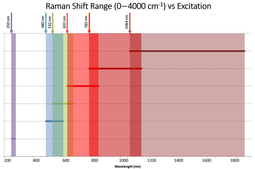
Aerospace 2021, 8, 173                                                                                            2 of 20

                               An in-situ analysis of the atmosphere, as proposed here, can be realised using com-
                         bined Raman spectroscopy and a laser-induced fluorescence (LIF) device. Measurements
                         from such instruments would improve our understanding of the composition and be-
                         haviour of the planet’s atmosphere. The need for spectroscopy experiments to study the
                         clouds of Venus has also been stressed by earlier mission proposals [3]. Furthermore,
                         performing atmospheric spectroscopy with balloon probes was suggested by the Venus
                         Science and Technology Definition Team in 2009 [11]. A recent example is the Russian
                         Venera-D mission [12], with an instrument package including an imaging camera, a gas
                         chromatography–mass spectrometer, an alpha P-X-spectrometer, a gamma spectrometer,
                         a laser spectrometer, a hazemeter, and a seismic detector [13]. The spectrometer uses a
                         multi-channel tunable diode laser spectrometer. Furthermore, NASA started developing
                         ideas for a CubeSat mission and descending probes for studying Venus’ atmosphere that
                         incorporate similar instruments [14,15].
                               The goal of the work presented here is to identify the specific science to be conducted
                         in-situ, to propose an optical payload baseline design for an atmospheric probe, and to
                         present a rough estimation of the system design budget for the realisation of the mission.

                         1.2. Missions to the Atmosphere of Venus
                               The history of Venus exploration started in the early 1960s with the first Soviet missions
                         performing flybys and eventually landings (in the 1970s). Although these first missions
                         were not as successful as planned, they paved the way for future Soviet missions, which
                         could finally analyse the planet’s atmosphere. The first successful atmospheric mission,
                         the Venera 4 probe (383 kg), was carried out by the Soviet Union in 1967 [16]. The mission
                         already included a UV spectrometer that helped to analyse its atmospheric composition for
                         the very first time. In 1985, the Vega balloon probes successfully studied the atmosphere of
                         Venus at an altitude of around 50–55 km. The use of a helium balloon, deployed by the
                         descending probe, helped scientists to obtain a much longer analysis time and region of
                         study, due to the dense atmosphere composition and presence of strong winds [17]. Earlier,
                         in 1978, NASA had sent the Pioneer Venus multiprobe (around 600 kg), which performed
                         an analysis of the atmosphere with different independent probes and instruments (amongst
                         others, a mass spectrometer and gas chromatograph to measure atmosphere composition,
                         a cloud particle size spectrometer, and temperature and pressure sensors) [18].
                               In 2005, ESA launched its first mission to Venus, the Venus Express. The spacecraft
                         spent more than eight years studying Venus and its atmosphere, mainly focusing on high-
                         resolution imagery and spectroscopy. Venus Express was a European flagship mission
                         that inspired many other mission concepts. It was followed by Akatsuki, a successful
                         Japanese Venus mission [19]. However, from the 1960s to the 1980s, no further landing
                         probes were sent into the planet’s atmosphere. Nowadays, the technical advances in
                         Raman spectrometry allow for more accurate and extensive analysis than the missions four
                         decades ago. Moreover, new technological developments allow the use of a considerably
                         smaller and lighter platform, which can result in a significantly more cost-effective mission.
                               In June 2021, both ESA [20] and NASA [21] announced the selection of three new
                         missions to explore Venus. ESA is planning to launch EnVision in 2032 [22] to address
                         three main aspects of our neighbour planet: its history (evolution of surface and interior),
                         its geological activity, and its climate. NASA is expecting to launch another two proposed
                         missions around 2028–2030. DAVINCI+ will be an atmospheric mission with a descent
                         sphere to understand the formation and evolution of the planet, and to also determine
                         whether Venus has ever had an ocean. VERITAS (SAR mission like EnVision) aims at
                         mapping the geological history and development of the planet. The newly selected missions
                         are all unique and complementary.

                         1.3. Space Raman Devices
                              Raman spectroscopy is an interesting technology for planetary science, since it allows
                         for in-situ analysis of samples thanks to the inelastic scattering of light. Fundamentally,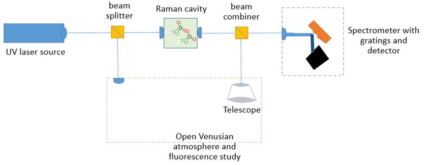
Aerospace 2021, 8, 173                                                                                                   3 of 20

                         the instrument only requires a narrow light excitation source, usually realised by a laser,
                         and a spectrometer to analyse the Raman light shift (Figure 1). The latter provides accurate
                         information about the vibrational and rotational molecule levels of the illuminated sample.
                         Raman spectroscopy can measure samples at a distance of up to 200 m and is therefore
                         useful for long-range atmospheric measurements [23].

                         Figure 1. Raman shift range versus laser excitation. Raman shift or excitation of bounced light into
                         the target material depends on the excitation source/laser. For a certain wavelength input, a different
                         output shifted wavelength is obtained with different peaks. This shift can be used to identify the
                         analysed molecules. Reprinted from [24].

                              Raman spectroscopy allows for precise identification of both mineral and organic
                         phases down to sub-picogram levels [25] without disturbing the analysed sample. This
                         analysis can be conducted in any state in which the sample is found (solid, liquid, or gas)
                         and with micrometre resolution. In addition, Raman spectroscopy is a very fast technique
                         that allows measurement within a few seconds. Along with this, the data products are
                         very simple, so the memory consumption and processing requirements are minimal. This
                         technique can be applied both in contact mode, bringing the signal through optics and
                         fibres to the spectrometer, as well as remotely, from a few centimetres to tens of metres.
                         Contact measurements can be done using a continuous laser and in low light conditions,
                         while remote acquisition is carried out using a pulsed laser.
                              Over the last decades, several research groups have been developing compact Raman
                         systems that are capable of operating in extreme space and planetary environments. In 2006,
                         a team at the University of Hawaii implemented several changes to standard Raman
                         spectroscopy devices to be able to create a small portable system for outdoor operation [26].
                         Already planning for space exploration, they designed a device with a 532 nm laser, an
                         energy of 35 mJ, and 8 ns pulses. The team reported that they were successful in their
                         goals, thanks to the use of volume holographic transmission gratings with a resolution
                         of 9 cm−1 . The device used a Nd:YAG laser with second harmonic generation (SHG) to
                         obtain the 532 nm emission. The incoming light from the sample was later collected using
                         a Makusutov Cassegrain 127 mm telescope [26].
                              Furthermore, several planetary missions are currently using compact Raman devices
                         to perform research, the most recent example being NASA’s Mars 2020 mission [27]. Its
                         rover Perseverance uses the SuperCam instrument to perform Raman spectroscopy at up to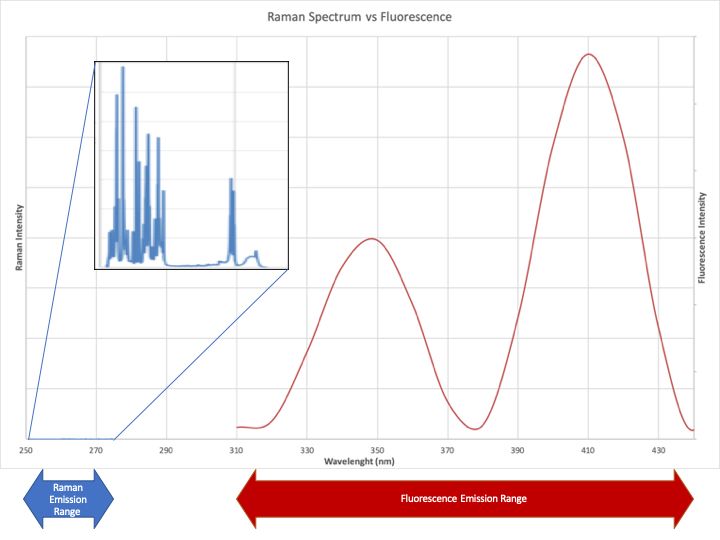
Aerospace 2021, 8, 173                                                                                              4 of 20

                         7 m distance. SuperCam includes, in addition to Raman, a suite of measurement techniques
                         such as Laser-Induced Breakdown Spectroscopy (LIBS), Time-Resolved Fluorescence (TRF)
                         spectroscopy, Visible and InfraRed (VISIR) reflectance spectroscopy, and high-resolution
                         visual imaging. The mission also uses a robotic arm that includes the Scanning Habitable
                         Environments with Raman & Luminescence for Organics & Chemicals (SHERLOC) Raman
                         device, to perform proximity measurements with a 248.6 nm laser emission [27]. Similarly,
                         ESA is planning to launch an instrument in the frame of the ExoMars mission in 2022,
                         which will also have Raman capabilities [28].
                               A Raman instrument specifically designed for the investigation of Venus’ atmosphere
                         would be very suitable for the detection of amino acids and their precursors. There
                         is already extensive experience in the use of this technology in the determination and
                         differentiation of amino acids in various environments, whether deposited on inorganic
                         surfaces, in solution, or in aerosols. In addition, the Raman spectroscopy technique is
                         capable of distinguishing types of amino acid by generating a unique fingerprint based
                         on its molecular composition. Moreover, recent publications [9] state that phosphine in
                         Venus’ atmosphere could be produced by certain types of bacteria. This can also be easily
                         studied with a Raman technique. The Raman shift range between 500 and 1700 cm−1
                         provides a sufficient signal for the precise determination of target amino acids (Figure 1).
                         In particular, performing distance Raman and fluorescence analysis using a pulsed UV
                         excitation source can help to determine the presence of organics, amino acids, or other
                         more complex biomarker molecules in Venus’ atmosphere (Figure 2).

                                                           Raman3Spectrum3vs3Fluorescence

                                                       Raman
                                                       Emission
                                                       Range

                                                                                                                    Fluorescence3Intensity
                         Raman3Intensity

                              250          270   290      310     330    350      370       390     410      430
                                                                  Wavelength3(nm)
                                                                       Fluorescence3Emission3Range

                         Figure 2. Raman and fluorescence emission ranges for a 250 nm excitation. Reprinted from [24].

                         1.4. Venus Atmospheric Conditions
                               One major constraint of performing Raman spectroscopy in Venus’ atmosphere is the
                         presence of extreme and challenging conditions under which the entire probe will have
                         to operate. The investigation of existing chemicals and possible amino acids requires the
                         probe to operate in highly variable pressure and temperature regimes, depending on the
                         altitude [6,29].
Aerospace 2021, 8, 173 5 of 20
The atmosphere of Venus is commonly divided into the lower, middle, and upper
atmosphere. The lower atmosphere commonly refers to the region below ∼65 km above
the surface, while the middle atmosphere ranges from ∼65 to ∼95 km and includes the
stratosphere and the mesosphere [30]. The upper atmosphere is the region above ∼95 km
and includes the thermosphere and the exosphere [30]. The atmospheric region of interest
for the present study is between 40 and 70 km altitude. Here, the temperature and pressure
varies from approximately 225–400 K and 10–1000 mbar, respectively [6,30,31]. Figure 3
shows the density and temperature versus altitude and pressure, as obtained from the
Venus International Reference Atmosphere (VIRA) model. VIRA was originally published
in 1985 [32] and has since been updated continuously as new data and important findings
were provided by later Venus missions, such as Vega 1, Vega 2, and Venus Express, and
by new ground based observations. Venus has a dense cloud layer that ranges from
around 48 to 65 km, above which the particle concentration falls off with a scale height of
around 3 km [30]. The different cloud layers and their respective altitude ranges are also
shown in Figure 3. The clouds are primarily composed of liquid droplets of sulphuric acid
(H2 SO4 ) [30].
−5 −4 −3 −2 −1 0 1 2
−1
Targeted
altitude
range
Figure 3. Atmospheric density (red line) and temperature (black line) versus altitude and pressure,
based on the VIRA model. Figure adapted from Figure 1 in [33].
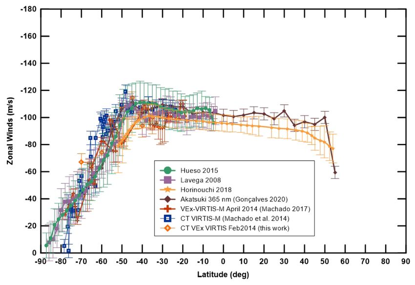
Recent studies [34–36] combine the analysis of zonal winds at Venus’ cloud-top from
observations in space and on the ground. A clear common wind profile, between 50 degrees
south and 50 degrees north (midlatitude region) with an average value of 100 m/s, can be
seen in Figure 4. At around 50 degrees, a smooth jet of, at most, 10 m/s is noticeable in
both hemispheres, whereas at higher latitudes there is a steady and steep decrease. For the
purpose of the present study, an average zonal wind velocity of 100 m/s can be considered.
These strong winds make balloon exploration very favourable, since the probe would be
able to travel horizontally, covering vast atmospheric areas [37]. The Soviet Vega 1 and
2 missions in 1985 had already taken advantage of this, and a similar approach was also
proposed to ESA in 2013 in response to the Cosmic Vision Call for Ideas [38].Aerospace 2021, 8, 173 6 of 20
Figure 4. Space and ground observation results of zonal wind latitudinal profiles at Venus’ cloud-top
(70 km). Reprinted from [36].
The atmosphere of Venus is composed of 96.5% CO2 , 3.5% N2 , and several trace
gases, such as SO2 , Ar, H2 O, CO, He, and Ne. The individual abundance in the region
of interest is listed in Table 1. HCl, Kr, HF, and Xe have also been observed, but with an
abundance between 1ppb and 1 ppm [30]. A recent detection of PH3 , with an abundance
of around 20 ppb above 48 km, sparked new interest in the search for life on Venus [9].
Investigation of various chemical processes that could be the source of the PH3 suggested
that no currently known process could explain the detection. The presence of PH3 was
suggested to be due to some unknown photochemistry or geochemistry process, or due to
the presence of life [9]. The planet-averaged PH3 abundance was later revised to 1–4 ppb,
with peaks at 5–10 ppb [39]. However, the presence of PH3 in the atmosphere of Venus is
controversial and has been questioned by recent studies. For example, [40,41] showed that
the data processing method used by [9] can result in spurious lines, including the spectral
feature of PH3 .
Table 1. Composition of the atmosphere of Venus. The given abundances are obtained from [30,42,43].
Gas Abundance
Carbon Dioxide (CO2 ) 96.5%
Nitrogen (N2 ) 3.5%
Sulfur Dioxide (SO2 ) 10–260 ppm
Argon (Ar) 20–200 ppm
Water Vapour (H2 O) 20–30 ppm
Carbon Monoxide (CO) 17–40 ppm
Helium (He) 12–17 ppm
Neon (Ne) 5–7 ppm
2. Proposed Mission Scenario
2.1. Mission Objectives
The overall scientific objective of the proposed mission is to characterise the abundance
of biomarkers (phosphine, amino acids, and other constituents) in the atmosphere of Venus.Aerospace 2021, 8, 173 7 of 20
To ensure the achievement of this objective, the following top-level mission requirements
are derived:
• TR1: The mission shall be able to determine the atmospheric conditions and com-
position, particularly the presence and abundance of phosphine and other relevant
biomarkers in the atmosphere of Venus at altitudes between 40 and 70 km.
• TR2: The UV absorption characteristics shall be analysed in different atmospheric
regions of Venus.
• TR3: The mission shall be feasible within a budget of a maximum of 50 million Euro
(ESA S-class mission).
• TR4: The mission shall achieve flight readiness level in less than 4 years.
• TR5: Commercial off-the-shelf (COTS) components should be used wherever possible,
to demonstrate their suitability for space exploration missions.
• TR6: The probe’s lifetime in the atmosphere of Venus shall be a minimum of two weeks.
The current state-of-the-art technologies required to satisfy the above requirements
allow for a mission with moderate cost and fast development [37], as compared to previous
Venus probes. A small probe that makes use of COTS components for nanosatellites is
presented here, taking advantage of the existing standardisation in this field and the wide
availability of components. The probe, comprising the scientific payload and all required
subsystems for survival, shall be carried on an atmospheric balloon to enable long-term
observations in the atmosphere.
2.2. Flight Opportunities
The proposed probe shall be launched as a secondary payload together with a pri-
mary mission, which will also deliver it to the atmosphere of Venus. The main reason
for this approach is to reduce cost and development time. Besides the shared launch
opportunity, the mission shall use the existing communication/relay network established
for the primary mission. A potential joint flight opportunity would be the ESA mission
EnVision. The proposed baseline launch date for EnVision is 2032, with a back-up date
in 2033. EnVision is planned to be launched with Ariane 62 into a Highly Elliptical Orbit
(HEO). Once in HEO, two escape sequence manoeuvres will take the spacecraft into the
interplanetary transfer trajectory, a phase that will last 134 days. After the Venus Orbit
Insertion (VOI), the spacecraft will go through an aerobraking phase of around 25 months,
which will lower the apoapsis from 250,000 to 470 km while holding the periapsis at 220
or 250 km. With this suggested mission timeline, the total EnVision mission duration will
range from 5.1 to 6.3 years, depending on the launch date [44].
As a secondary payload, the proposed Venus probe will be able to use EnVision’s
Earth communication link, thus reducing the antenna requirements. Furthermore, the
launch costs will be shared.
3. Probe Design
Figures 5 and 6 show the preliminary design and configuration of the probe. The instru-
ment section in the lower compartment encloses a volume of approximately 200 × 300 × 100 mm
and contains the UV laser, spectrometer, telescope, and camera. The electronics compartment
with dimensions 200 × 300 × 200 mm contains the battery (BAT), the power control and distri-
bution unit (PCDU), the communications unit (COM) with the S-band antenna module, and the
onboard computer (OBC). The probe also includes a number of additional sensors to measure
the atmospheric ambient conditions, such as temperature, pressure, humidity, and wind speed.
At the sides of the electronics section, the parachutes and the balloon are stowed, together with
the deployable antennas. The heat shield at the bottom of the probe protects the probe during
entry and will be ejected after arriving at the altitude targeted for balloon deployment.
Table 2 shows the average system power and mass budgets. Regarding the power and
mass requirements of the science payload, the NASA SHERLOC instrument [45,46] serves
as an example.Aerospace 2021, 8, 173 8 of 20
The balloon consists of the floating mass, which is comprised of the balloon fabric,
the buoyant gas, and the gondola, which carries the scientific payload. The floating mass
is contained in the entry capsule together with the parachute. Additionally, the capsule
includes the inflation mechanism and balloon support structure. The mass breakdown for
the entry capsule is not accounted for in Table 2, however, for the 9 kg payload, a maximum
of 115 kg would be needed to bring the science probe into the atmosphere [47] (compared
to the planetary capsules designed for missions of a similar size [48]). Given the new
technological material developments in the area of lighter-than-air systems, it is very likely
to even further reduce the mass budget [49].
Figure 5. Conceptual design of the proposed Venus probe in stowed (left, during cruise and entry) and deployed (right,
during operations in the atmosphere) configurations.
Figure 6. Detailed views of the electronics and instrument compartment of the probe, showing dummy volumes for the
subsystems (housing not shown on right image).Aerospace 2021, 8, 173 9 of 20
Table 2. System power and mass budget.
Device/Instrument Power [W] Mass [kg]
(Added Individual Margin) (Added Individual Margin)
Science payload 1
Payload Raman
(UV laser/Telescope/Spectrometer) 55.0 (10%) 1.7 (5%)
Science payload 2
High-resolution camera
(Imperx B3412) 5.4 (5%)Aerospace 2021, 8, 173 10 of 20
States), in a mission to Jupiter’s moon Europa. The mission plans to use a combination of
fluorescence/Raman instruments to search for organic material [55]. Thus, the following
instrument baseline architecture is suggested (see Figure 7) [24]:
• The UV laser source is separated using beam-splitters to transport the emitted light in
free space into the different regions of study:
– One of the beams is directed into a small probe side cavity (a few mm). Across
the cavity, designed to stabilise the atmosphere, the device performs transmis-
sion Raman. On the opposite side of the cavity, the receiving optics guide the
incoming light into the spectrometer. The instrument would be able to provide a
more accurate study of single proximity molecules and possible amino acids.
– The other beam is directed through an aperture into the atmosphere. The laser
illuminates a few tens of metres and the fluorescence signal is collected with a
small telescope (around 100 mm aperture).
• Both fluorescence and Raman signals are joined using a beam combiner. The incoming
signals are independently analysed using a single spectrometer. The Raman signal is
used to study the chemical bonds and possible functional groups of the molecules,
while the fluorescence signal is focused on electronic structure to analyse aromatics
and aldehydes [56].
Figure 7. Schematic of the instrument baseline. The laser is obliquely placed near the receiving tele-
scope.
The laser source and sensitive spectrometer parts need to be protected from the
extreme environment and therefore accommodated inside the instrument compartment of
the probe.
Due to the temperature ranges of the atmosphere and the interest in studying the
presence of amino acids and their response to certain wavelengths, the proposed excitation
source is in the UV region, where these molecules show great absorption and fluorescence.
UV lasers have recently been market accessible [57]. Even if, nowadays, reliable UV lasers
can perform Raman spectroscopy in a laboratory environment, the laser qualification for
space missions is not yet a straightforward and standardised process [58]. However, there
are examples of space-qualified UV laser spectrometer devices, such as the SHERLOC
instrument of the Mars 2020 mission [27] or the UV-DPSS of the MOMA (Mars Organic
Molecule Analyser) instrument on the ExoMars 2022 mission [59].
Different instrument options are available for this mission, however, the best solution
will always be a trade-off between science capabilities (different sample analysis and used
methods) and the mission constraints (budgets and environmental conditions). Due to
the principal objective of studying larger molecules, plus budget constraints and space
heritage, the preferred baseline is an NeCu hollow cathode ion laser, emitting at 248 nm
wavelength [60], similar to the one used for the SHERLOC instrument [61]. Other UV
configurations, for instance changing the hollow cathode ion laser to a frequency dou-Aerospace 2021, 8, 173 11 of 20
bled solid state laser, or even tunable lasers with a wider emission wavelength [62], are
possible alternatives.
Within this mission concept, it is proposed to perform a time-resolved Raman anal-
ysis [23] by using an intensified charge-coupled device (ICCD) time gated measurement
detector, to better separate the Raman and fluorescence signals.
Additionally, the science payload includes a high definition camera for the visualisa-
tion of the analysed atmosphere region. Miniaturised COTS cameras for such purposes
have been widely implemented in space missions over the recent decades [63]. For the
proposed concept, the HiREV2 camera [64] was selected.
3.2. Power
The power subsystem architecture represents one of the major design trade-offs. Using
an architecture to manage either non-rechargeable battery cells or rechargeable cells has
a considerable effect on the mission performance, especially regarding the system mass
and complexity, as well as the mission duration. The first option (non-rechargeable cells)
was selected as the baseline, while the second one (rechargeable cells) was studied as an
alternative. Both options are analysed in the following sections.
3.2.1. Option 1: Non-Rechargeable Cells, No Solar Arrays
Non-rechargeable battery cells show a superior power density compared to recharge-
able ones. Their main drawback is that, in contrast to a solar-array-based power subsystem,
the mission will be terminated as soon as the batteries are depleted. On the other hand,
the electrical power system is simpler, since no solar array regulators (SARs) are needed,
complemented by a simplified structure of the probe that does not require any deploy-
ment mechanism.
Battery Sizing
Several battery cells have been investigated, focusing on lithium-based Li-SOCl2 and
Li-SO2 , given their outstanding energy density [65]. Table 3 shows their main characteristics.
It can be seen that the LSH20-150 cell offers a distinct extended operating temperature
range, which could be interesting for exploring a wider atmosphere area. On the other
hand, the LS33600 cells show the highest energy density, leading to a lower system mass.
Table 3. Characteristics of investigated non-rechargeable battery cells.
Cell name LS14250 LS33600 LSH20 LSH20-150 LO34SX LO25SX LO 29 SHX LO 39 SHX G 06/6 G 62/1
Type Li-SOCl2 Li-SOCl2 Li-SOCl2 Li-SOCl2 Li-SCl2 Li-SCl2 Li-SCl2 Li-SCl2 Li-SCl2 Li-SCl2
Energy [Wh] 4.3 61.2 46.8 50.4 2.8 22.4 10.5 32.2 2.7 95.2
Typical weight [g] 8.9 90 100 104.5 16 96 40 125 15 300
Operating temp. [◦ C] −60/+85 −60/+85 −60/+85 −40/+150 −40/+70 −60/+70 −60/+70 −60/+70 −60/+70 −60/+70
Energy density [Wh/kg] 485.4 680.0 468.0 482.3 175.0 233.3 262.5 257.6 177.3 317.3
The mission requirement TR6 states that the system shall be operating for at least two
weeks. The instrument measurements can be performed in a few seconds and repeated
with a certain frequency over that period of two weeks. There is a compromise between
the available energy and the mass of the system. Therefore, it was assumed that the battery
should provide enough energy storage to operate for a total time of 12 h, distributed over
the nominal mission duration, at the maximum power level of 109.3 W as stated in Table 3.
With this assumption, the required energy is 1.3 kWh. Table 4 summarises the required
battery module configuration (number of cells in a series, assuming a 28 V bus voltage and
cells in parallel, to provide enough energy and discharge capability) and the corresponding
mass for all the analysed non-rechargeable battery cells.Aerospace 2021, 8, 173 12 of 20
Table 4. Required number of non-rechargeable cells and corresponding mass, excluding the module mechanical assembly.
Cell name LS14250 LS33600 LSH20 LSH20-150 LO34SX LO25SX LO 29 SHX LO 39 SHX G 06/6 G 62/1
Type Li-SOCl2 Li-SOCl2 Li-SOCl2 Li-SOCl2 Li-SCl2 Li-SCl2 Li-SCl2 Li-SCl2 Li-SCl2 Li-SCl2
Series cells 8 8 8 8 10 10 10 10 10 10
Parallel cells 38 3 4 4 47 6 13 5 50 2
Cells mass [kg] 2.7 2.2 3.2 3.3 7.5 5.8 5.2 6.3 7.5 6
Total mass [kg] 3.2 2.6 3.8 4.0 9.0 6.9 6.2 7.5 9 7.2
The option with LS33600 cells appears to be the most suitable option in terms of mass.
However, for the sake of extending the possible altitude range of the probe with respect to
ambient temperatures, the battery module with LSH20-150 cells is preferable. Furthermore,
the mass of the LSH20-150 modules is still in a feasible range. Hence, the selected battery
module uses LSH20-150 cells, in a configuration of 8s4p (eight cells in series, four in
parallel), with a total assembly mass of 4 kg.
Architecture
There are two options regarding the bus voltage: regulated or unregulated. For the
first case, only a Battery Discharge Regulator (BDR) is required to keep the bus voltage
at 28 V. This BDR must include overdischarge protections, maximum current discharge
control and high output dynamics. For the second case, the batteries would determine the
bus voltage, leading to a voltage range from 16.8 V to 29.4 V with the LSH20-150 battery.
Nevertheless, overdischarge protections must also be included in this option. Given the
sensitivity of the instrument, a regulated bus voltage is preferable. The Power Conditioning
and Distribution Unit (PCDU) must also include a dedicated power supply for the UV
laser [46].
3.2.2. Option 2: Rechargeable Cells and Solar Arrays
Despite the adverse environmental conditions of Venus’ atmosphere, a solution with
solar cells might potentially be feasible [66]. Adding solar arrays to the probe increases
the system complexity, since SARs are required to condition the power they provide, as is
a BCDR module to regulate the charge and discharge of the batteries. Nevertheless, this
design option provides continuous electrical power generation during daytime, allowing
to recharge the batteries and hence enabling a much longer mission duration. On the
other hand, the operating temperature of these batteries is more restrictive, which would
limit the altitude range that can be explored. Hence, this option is analysed just as a
secondary alternative.
The batteries are considered as a backup electrical energy storage, either to comple-
ment the solar arrays to provide some extra peak power or to provide some energy in
survival mode (i.e., when the solar arrays are not capable of providing enough power for
the platform).
Battery Sizing
Despite the lower energy density of rechargeable battery cells compared to non-
rechargeable ones, they will be recharged by the solar arrays, ultimately leading to a longer
lifetime. Nevertheless, the measurements shall be duty-cycled in order to keep a positive
energy balance.
Table 5 shows the main characteristics of several Lithium-ion cells [65]. Despite
showing the highest energy density, the maximum operating temperature of the MP 176065
xlr cells is constrained to 60 ◦ C. For this mission, MP 176065 xtd cells are more suitable,
since they can be operated up to 85 ◦ C and the energy density is close to that of the
previous cells.Aerospace 2021, 8, 173 13 of 20
Table 5. Characteristics of investigated rechargeable battery cells.
Cell name MP 174565 XTD MP 176065 XTD VL 34570 xlr MP 176065 xlr VES16
Type Li-ion Li-ion Li-ion Li-ion Li-ion
Life cycles @100DoD,
C-C/2, 25 ◦ C 2700 2700 600 1800 5000
Energy [Wh] 14.6 20.4 19.7 24.8 16
Typical weight [g] 97 135 130 150 155
Discharging temp. [◦ C] −40/+ 85 −40/+ 85 −35/+60 −35/+60 +10/+40
Charging temp. [◦ C] −30/+ 85 −30/+ 85 −30/+60 −30/+60 +10/+40
Energy density [Wh/kg] 150.5 151.4 151.6 165.5 103.2
As mentioned in the previous section, mission objective TR6 establishes that the life-
time of the probe should be at least two weeks. The solar cells will provide continuous
power during the daytime, although the effective solar flux diminishes with lower altitudes.
Hence, the batteries should be sized to provide at least 2 h of continuous discharge at the av-
erage power from Table 5 (109.3 W, 2 h, 80% DoD, 90% retained energy at EOL = 303.6 Wh
nameplate energy) and also to provide at least enough energy for a pulse with the peak
power (130 W, 60 µs = 7.8 mWh ). Hence, batteries must have a nameplate energy higher
than 303.6 Wh. This way, once the batteries reach 80% DoD, the payload would remain
inactive until the batteries are recharged again if the solar arrays are receiving sunlight.
Otherwise, if the probe is in eclipse condition after those two hours, the whole platform
would remain dormant until sunlight is received again so that the batteries will start being
recharged again.
Considering a DoD of 80% would lead to a degradation below 90% at EOL (assumed
2 months, depending on the descending speed, hence on the temperature and the frequency
of the measurements too), approximately. Applying these factors, the required mass of
battery cells is shown in Table 6 for different cells.
Table 6. Required number of rechargeable battery cells (series and parallel), cells’ mass and total
mass of the battery module (including the mechanical assembly and electrical connectors).
Cell name MP 174565 XTD MP 176065 XTD VL 34570 xlr MP 176065 xlr VES16
Type Li-ion Li-ion Li-ion Li-ion Li-ion
Series cells 8 8 8 8 8
Parallel cells 3 2 2 3 3
Cells mass [kg] 2.3 2.2 2.1 2.4 3.7
Total mass [kg] 2.8 2.6 2.5 2.9 4.5
MP 176065 xtd cells are selected as an alternative battery for this mission due to their
wide operating temperature range. Since its nominal voltage is 3.65 V, the configuration
of the battery module must be 8s2p (eight cells in series, two in parallel). With this
configuration, the mass of the battery only is 2.4 kg and 2.9 kg after adding the mass of the
electrical connectors and the mechanical assembly.
Solar Array Sizing
There are different factors that influence the performance of the solar cells in the
atmosphere. The absorption and scattering of the light depends on the altitude, and is
mainly affected by the thick main cloud layer (48 km to 65 km). Furthermore, the tem-
perature increases with lower altitudes, hence reducing the efficiency of the solar cells.
The generated power is also dependent on the Sun angle, therefore the equator is the most
favourable scenario in terms of power due to a higher angle of incidence. Furthermore,
the clouds contain corrosive components, so a special coating would be required for the
solar arrays.
As mentioned in Section 1.4, the region of interest is the equator, targeting altitudes
from 40 km to 70 km, although, as will be shown in the next section, altitudes below 55 km
might not be feasible from a thermal perspective. The corresponding power generated perAerospace 2021, 8, 173 14 of 20
unit area of triple-junction solar cells is 112.2 W/m2 , 256 W/m2 and 700 W/m2 for 40 km,
55 km and 70 km, respectively [66].
The simplest option would be mounting as many cells as possible on the top surface
of the probe, whose size is 300 × 200 mm (see Figure 5). Assuming a packing factor of
85%, it is possible to mount 16 Azurspace (AZUR SPACE Solar Power GmbH, Heilbronn ,
Germany) 3G30 cells, leading to 0.048 m2 of cell surface.
Another option is adding deployed panels to expand the solar array (SA) surface,
at the expense of increasing the mass of the probe and the complexity of the mechanical
structure of the probe and the additionally required deployment mechanism. In this case,
there would be two 300 × 200 mm panels in addition to the previous body mounted.
In other words, the solar cell surface would be triplicated, leading to 0.145 m2 .
Lastly, in order to further increase the power generated, these deployed SA can be
doubled. As a consequence, the solar cells’ surface is multiplied by five compared to the
body-mounted option.
Table 7 summarises the power generated with these two options depending on the
altitudes of interest.
Table 7. Power generated by different solar array configurations at different altitudes.
Altitude (power per unit area) 40 km (112.2 W/m2 ) 55 km (256 W/m2 ) 70 km (700 W/m2 )
1 body mounted SA (16 cells = 0.048 m2 ) Power [W] 5.4 12.3 33.7
1 body mounted + 2 deployed SA = 48 cells = 0.145 m2 ,Power [W] 16.2 37.0 101.2
1 body mounted + 4 deployed SA = 80 cells = 0.241 m2 ,Power [W] 27.0 61.7 168.7
Operating at 40 km should be regarded as a critical case, due to thermal constraints.
On the other hand, at 55 km, none of the options are capable of providing enough power
to operate the complete system continuously with only the power from the SA. Therefore,
the SA must be used only to charge the batteries, but not to supply all subsystems in a
continuous manner. Instead, instruments and communications shall be duty-cycled in
order to ensure a positive energy balance.
With the aim of increasing the reliability of the system, the option with a body mounted
panel is more suitable and the mass increase due to this SA is just 400 g. However, the main
drawback is the long time required to recharge the batteries (about 9 h, at 55 km altitude,
to recharge after 1 h of operations with all subsystems active).
The other options with two or four deployed SA would increase the mass by 1.2 kg
and 2.4 kg on top of that. In addition, these options would require a deployment mech-
anism, which might introduce some risk—the mission would be compromised if this
mechanism fails.
Architecture
As mentioned above, a regulated bus is preferable given the sensitivity of the instru-
ment. However, in this case, not only is a BDR required, but also a BCDR and an SAR.
The SAR can be implemented either using Maximum Power Point Tracking (MPPT) or
a Sequential Switching Shunt Regulator (S3R). MPPT is more suitable, since it is able to
maximise the power that can be generated given the variable environmental conditions
of this mission. There are some commercial EPS compatible with these features, such
as [67,68], although an additional specific power supply for the UV laser must be included
in the PCDU.
3.2.3. Selected Option and Performance
Given the characteristics of the mission and with the aim of maximising the reliability
while minimising the system mass and complexity, the selected power subsystem consists
of non-rechargeable cells (in particular, a battery module with LSH20-150 cells, with a 8s4p
configuration) and a PCDU, which contains a BDR to regulate the bus voltage to 28 V andAerospace 2021, 8, 173 15 of 20
a dedicated power supply for the instrument’s laser. With this configuration, the target of a
two week lifetime is achieved by duty-cycling the instruments.
3.3. Thermal
Following the mission objective TR1 (see Section 2.1), the probe should operate at an
altitude between 40 and 70 km. The estimated ambient conditions in this altitude region
are temperatures of 225–400 K (−48 to 127 ◦ C), pressures on the order of 10–1000 mbar
and wind speeds around 40–100 m/s. Temperature profiles measured by earlier missions,
such as Vega-2 and the Pioneer Venus probes, indicate a very low temporal and spatial
variability on the order of 5 K at a given pressure or altitude level [33,69].
The main subsystems of the probe impose thermal requirements on the design, as
summarised in Table 8. It is clear from these requirements that the upper end of the
expected temperature range will be more challenging for the thermal design than the
lower temperatures. High-performance insulation can be utilised to protect the probe
from the hot atmosphere. Aerogels, multi-layer-insulation (MLI) and phase-changing
materials (PCM) have previously been identified as relevant technologies to extend the
lifetime of Venus probes [70]. However, it needs to be considered that not all of these
materials might be qualified for high-temperature or high-g entries. The efficiency of
porous insulators like aerogel and MLI also heavily depends on gas pressure, hence they
typically find their application in the free molecular flow regime. Due to the ambient
pressure of approximately 10–1000 mbar in the targeted altitude range, passive cooling and
heating is mainly achieved via convection. Active cooling options include heat pipes and
miniaturised cryo-coolers, but these require additional mass and power and only provide
limited cooling capability on this small scale.
Table 8. Temperature requirements (non-operational and operational) and estimated heat dissipation of all subsystems.
Subsystem Non-Op Min [◦ C] Op Min [◦ C] Op Max [◦ C] Non-Op Max [◦ C] Heat Dissipation [W]
UV laser a n/a −135 70 n/a 3.4
Spectrometer −60 −30 50 70 8.2
Telescope −60 −30 50 70 3.4
Camera b −40 −30 60 85 1.0
BAT c n/a −40 150 n/a 0.6
PCDU d −40 −30 60 85 2.0–10.3
OBC −55 −30 85 125 0.4
COM e n/a −40 70 n/a 2.2
a Photon Systems NeCu laser, b Imperx B3412, c Saft LSH 20-150 (8s4p), d incl. laser power supply, e Gomspace ANT2000.
Due to the atmospheric gas pressure and wind speeds, the temperature at the external
surfaces is less sensitive to the orientation of the probe. Table 9 provides an overview of the
estimated flow conditions in the atmosphere at different altitudes, with associated ambient
temperature and pressure (compare Figure 3). The convective heat exchange coefficient
over a plate with length 300 mm, which equals the length of the probe’s external surface,
was calculated for a wind speed of 40–100 m/s, covering the relevant range at the expected
altitudes. The actual relative wind speed between the probe and the ambient atmosphere
is difficult to estimate at this stage, since this requires knowledge of the probe–balloon
dynamics and the relative motions involved. As Table 9 shows, the increasing temperature
and pressure at lower altitudes lead to an increasingly turbulent flow and thus to higher
heat transfer on the external surfaces of the probe. This further complicates maintaining
the operational temperatures within their limits at lower altitudes. Furthermore, in the
lower cloud (ca. 46–55 km), the probe will experience stronger updraft and downdraft
on the order of 2–3 m/s, which additionally contributes to a stronger convective heat
exchange [71]. Assuming an absolute worst case with no relative motion between the
atmosphere and the probe (and also neglecting natural convection), the maximum steady
state temperatures are 48 ◦ C at 70 km, 136 ◦ C at 55 km, and 223 ◦ C at 40 km, and thereforeAerospace 2021, 8, 173 16 of 20
clearly exceed the operational range. However, such a case is rather unlikely, as there will
always be convection to some extent.
Table 9. Estimated ambient conditions and calculated convective heat transfer properties for a 300 mm long plate. The value
range corresponds to wind speeds between 40 m/s and 100 m/s.
Max. Steady State Temp.
Altitude Temperature Pressure Reynolds Number Nusselt Number Heat Exchange Coefficient
(Science Payload Off)
70 km −48 ◦ C 10 mbar 1.9 × 10⁴ –4.8 × 10⁴ (laminar) 43–68 2–4 W/(m2 K) −45 . . . −43 ◦ C
55 km 40 ◦ C 100 mbar 1.4 × 10⁵ –3.4 × 10⁵ (laminar) 115–182 6–10 W/(m2 K) 41 . . . 42 ◦ C
1.4 × 10⁵ –3.4 × 10⁵ (turbulent) 356–741 20–41 W/(m2 K) 40 . . . 41 ◦ C
40 km 127 ◦ C 1000 mbar 1.1 × 10⁶ –2.7 × 10⁶ (turbulent) 1509–4004 84–223 W/(m2 K) 127 ◦ C
The preliminary thermal analysis showed that the steady state temperatures of the
components listed in Table 8 are only a few degrees above the ambient temperature for
different boundary conditions (Table 9). There are only very small thermal gradients
between the subsystems, because the inside of the probe is at ambient pressure. The results
suggest that the required operational temperatures can be maintained, at least in parts of the
targeted altitudes (55–70 km), representing the upper and middle cloud layer. Descending
further down, the minimum temperatures will ultimately reach the ambient value (127 ◦ C
at 40 km) in the absence of an active cooling mechanism. For operation at and above
70 km, with the science payload being switched off, the probe requires additional heaters to
maintain a safe margin to the minimum temperatures of all subsystems. With appropriate
insulation of the science payload, short excursions into cloud layers below 55 km might in
principle be possible, assuming a colder initial temperature when starting the descent.
To further investigate the transient thermal behaviour, a baseline operational mode
was applied to the science payload (UV laser, spectrometer, telescope and camera) with a
duty cycle of 60 s on, followed by 540 s off, so that a measurement is performed every 10 min.
The PCDU, onboard computer, as well as the communication subsystem and the sensors,
are constantly active during operations. The resulting temperature evolution is depicted
in Figure 8 for an altitude of 70 km (−48 ◦ C and 10 mbar ambient) and 55 km (40 ◦ C and
100 mbar ambient). The proposed duty cycle appears to be appropriate for limiting the
temperature increase during nominal operation to a few degrees, while providing sufficient
time for a full measurement with the spectrometer and imaging with the camera. However,
the presented thermal analysis is only preliminary and more details on the placement of
components and their material properties will have to be taken into account for a more
conclusive analysis.
Figure 8. Transient heating of the subsystems with baseline duty cycle of laser, spectrometer, telescope and camera.
The initial temperature equals the steady state temperatures with the aforementioned components switched off.Aerospace 2021, 8, 173 17 of 20
4. Conclusions
In the present work, a conceptual design for a small probe to study the atmoshpere of
Venus is proposed. The science objectives were analysed and it was shown that the mission
can be realised using existing COTS components (already used in previous space missions,
mainly LEO) that favour a lower total cost. Therefore, the indicated technical requirements,
TR3, TR4, and TR5 (see list of mission objectives in Section 2.1), can be satisfied.
The main technical challenge for the probe is the thermal control at lower altitudes,
where ambient temperature and pressure complicate the cooling of the internal compo-
nents. A preliminary analysis showed that, without active cooling mechanisms, the lowest
operational altitude of the probe should be approximately 55 km, where the temperature is
around 40 ◦ C. While it is recommended to use a science payload with flight heritage, such
as the SHERLOC instrument on board the Mars 2020 rover, it is also strongly recommended
to put effort into qualifying such instruments already available in Europe for operation in
space and planetary environments.
Here, a preliminary design is presented, based on the scientific payload using UV
and Raman spectroscopy together with a visual camera and a complementary sensor suite.
However, the current design is not limited to these instruments, and accommodation of
others, such as a nephelometer, might be a valuable addition. With the current scientific
instruments baseline, the mission will fulfill the scientific objective TR2. Furthermore, as a
detailed power system trade-off showed, the mission will be able to operate for several
days across different atmospheric regions, and thus satisfy the operational objective TR6.
Author Contributions: All authors contributed equally. All authors have read and agreed to the
published version of the manuscript.
Funding: This research received no external funding.
Institutional Review Board Statement: Not applicable.
Informed Consent Statement: Not applicable.
Data Availability Statement: Not applicable.
Acknowledgments: The authors want to thank Antonio Sansano-Caramazana, Helene Strese and
Luca Maresi, co-authors of a previous conference publication (ICSO2021), which inspired the idea for
the present article.
Conflicts of Interest: The authors declare no conflict of interest.
References
1. Cockell, C.S. Life on Venus. Planet. Space Sci. 1999, 47, 1487–1501. [CrossRef]
2. Grinspoon, D.H.; Bullock, M.A. Astrobiology and Venus Exploration. In Exploring Venus as a Terrestrial Planet; Esposito, L.W.,
Stofan, E.R., Cravens, T.E., Eds.; Wiley: New York, NY, USA, 2007. [CrossRef]
3. Limaye, S.S.; Mogul, R.; Smith, D.J.; Ansari, A.H.; Słowik, G.P.; Vaishampayan, P. Venus’ Spectral Signatures and the Potential for
Life in the Clouds. Astrobiology 2018, 18, 1181–1198. [CrossRef] [PubMed]
4. Limaye, S.; Bullock, M.A.; Baines, K.H.; Cockell, C.; Cordova, J.A.; Cutts, J.A.; Way, M.J. Venus, an Astrobiology Target. Bull. AAS
2021, 53. [CrossRef]
5. Otroshchenko, V.A.; Surkov, Y.A. The possibility of organic molecule formation in the Venus atmosphere, Origins of life. Springer
Exobiol. 1974, 5, 487–490. [CrossRef]
6. Taylor, F.W.; Svedhem, H.; Head, J.W. Venus: The Atmosphere, Climate, Surface, Interior and Near-Space Environment of an
Earth-Like Planet. Space Sci. Rev. 2018, 214. [CrossRef]
7. Seager, S.; Petkowski, J.J.; Goa, P.; Bains, W.; Ranjan, S.; Greaves, J. The Venusian Lower Atmosphere Haze as a Depot for
Desiccated Microbial Life: A Proposed Life Cycle for Persistence of the Venusian Aerial Biosphere. Astrobiology 2020. [CrossRef]
8. Andreichikov, B.M.; Mukhin, L.M.; Korchuganov, B.N.; Akhmetshin, I.K.; Tokarev, E.N.; Medvedev, A.V.; Goldfeld, M.N.;
Fajnbojm, V.M.; Kalyuzhnyj, A.V.; Petryanov, I.N.; et al. Element Abundances in Venus Aerosols by X-ray Radiometry—
Preliminary Results. Pisma Astron. Zhurnal 1986, 12, 120–122.
9. Greaves, J.S.; Richards, A.M.S.; Bains, W.; Rimmer, P.B.; Sagawa, H.; Clements, D.L.; Seager, S.; Petkowski, J.J.; Sousa-Silva, C.;
Ranjan, S.; et al. Phosphine gas in the cloud decks of Venus. Nat. Astron. 2020. [CrossRef]
10. Frandsen, B.N.; Wennberg, P.O.; Kjaergaard, H.G. Identification of OSSO as a near-UV absorber in the Venusian atmosphere.
Geophys. Res. Lett. 2016, 43. [CrossRef]Aerospace 2021, 8, 173 18 of 20
11. Bullock, M.A.; Senske, D.A.; Balint, T.S.; Benz, A.; Campbell, B.A.; Chassefiere, E.; Colaprete, A.; Cutts, J.A.; Glaze, L.; Gorevan,
S.; et al. A Venus Flagship Mission: Report of the Venus Science and Technology Definition Team. In Proceedings of the 40th
Lunar and Planetary Science Conference, The Woodlands, TX, USA, 23–27 March 2009.
12. Venera-D. Available online: https://www.esa.int/About_Us/ESA_Permanent_Mission_in_Russia/Venera-D (accessed on 17
June 2021).
13. Report of the Venera-D Join Science Definition Team. Venera-D: Expanding Our Horizon of terrestrial Planet Climate and Geology
through the Comprehensive Exploration of Venus. Available online: http://iki.rssi.ru/events/2017/venera_d.pdf (accessed on
17 June 2021).
14. NASA Venus CubeSat. Available online: https://www.nasa.gov/feature/goddard/2017/nasa-studies-cubesat-mission-to-solve-
venusian-mystery (accessed on 17 June 2021).
15. NASA Venus Probe. Available online: https://www.nasa.gov/feature/goddard/2020/nasa-goddard-team-selected-to-design-
concept-for-probe-of-mysterious-venus-atmosphere (accessed on 17 June 2021).
16. NASA Venus S/C. Available online: https://nssdc.gsfc.nasa.gov/nmc/spacecraft/display.action?id=1967-060A (accessed on 17
June 2021).
17. NASA Vega 2 Balloon. Available online: https://nssdc.gsfc.nasa.gov/nmc/spacecraft/display.action?id=1984-128F (accessed on
17 June 2021).
18. NASA Pioneer. Available online: https://solarsystem.nasa.gov/missions/pioneer-venus-2/in-depth/ (accessed on 17 June
2021).
19. Nakamura, M.; Titov, D.; McGouldrick, K.; Drossart, P.; Bertaux, J.; Liu, H. Special issue Akatsuki at Venus: The First Year of
Scientific Operation. Earth Planets Space 2018, 70, 1–3. [CrossRef]
20. ESA Selects Revolutionary Venus Mission EnVision (June 2021). Available online: https://www.esa.int/Science_Exploration/
Space_Science/ESA_selects_revolutionary_Venus_mission_EnVision (accessed on 21 June 2021).
21. NASA Selects 2 Missions to Study ’Lost Habitable’ World of Venus (June 2021). Available online: https://www.nasa.gov/press-
release/nasa-selects-2-missions-to-study-lost-habitable-world-of-venus (accessed on 21 June 2021).
22. EnVision, Understanding Why Earth’s Closest Neighbour Is So Different (Feb 2021). Available online: https://www.cosmos.esa.
int/documents/5763359/5763378/EnVision_YB_final.pdf/e9612355-67de-42a3-c25a-af1683f6fda3?t=1616679461807 (accessed on
21 June 2021).
23. Angel, S.M.; Gomer, N.R.; Sharma, S.K.; McKay, C. Remote Raman Spectroscopy for Planetary Exploration: A Review. Appl.
Spectrosc. 2012, 66, 137–150. [CrossRef]
24. Ribes-Pleguezuelo, P.; Sansano-Caramazanam, A.; Strese, H.; Maresi, L. UV-BIOmarker Mapper Raman optical instrument for
Venus AtmosPhere (UV-BIOMAP). In Proceedings of the International Conference on Space Optics—ICSO 2020, Virtual, 30
March–2 April 2021.
25. Bhartia, R.; Salas, E.C.; Hug, W.F.; Reid, R.D.; Lane, A.L.; Edwards, K.J.; Nealson, K.H. Label-Free Bacterial Imaging with
Deep-UV-Laser-Induced Native Fluorescence. Am. Soc. Microbiol. J. 2010, 76, 7231–7237. [CrossRef] [PubMed]
26. Misra, A.K.; Sharma, S.K.; Lucey, P.G. Remote Raman Spectroscopic Detection of Minerals and Organics Under Illuminated
Conditions from a Distance of 10 m Using a Single 532 nm Laser Pulse. Appl. Spectrosc. 2006, 60, 223–228. [CrossRef]
27. Beegle, L.; Bhartia, R.; White, M.; DeFlores, L.; Abbey, W.; Wu, Y.H.; Cameron, B.; Moore, J.; Fries, M.; Burton, A.; et al. SHERLOC:
Scanning habitable environments with Raman and luminescence for organics and chemicals. In Proceedings of the 2015 IEEE
Aerospace Conference, Big Sky, MT, USA, 7–14 March 2015; pp. 1–11. [CrossRef]
28. Ribes-Pleguezuelo, P.; Guilhot, D.; Gilaberte Basset, M.; Beckert, E.; Eberhardt, R.; Tünnermann, A. Insights of the Qualified
ExoMars Laser and Mechanical Considerations of Its Assembly Process. Instruments 2019, 3, 25. [CrossRef]
29. Venus Temperature Profile. Available online: https://www.esa.int/Science_Exploration/Space_Science/Venus_Express/The_
unexpected_temperature_profile_of_Venus_s_atmosphere (accessed on 18 June 2021).
30. Taylor, F.W.; Hunten, D.M. Venus: Atmosphere. In Encyclopedia of the Solar System; Spohn, T., Breuer, D., Johnson, T.V., Eds.;
Elsevier Inc.: Amsterdam, The Netherlands, 2014; pp. 305–322.
31. Tellmann, S.; Pätzold, M.; Häusler, B.; Bird, M.K.; Tyler, G.L. Structure of the Venus neutral atmosphere as observed by the Radio
Science experiment VeRa on Venus Express. J. Geophys. Res. 2009, 114, E9. [CrossRef]
32. Kliore, A.J.; Moroz, V.I. The Venus International Reference Atmosphere. In Advances in Space Research; Keating, G.M., Ed.; Elsevier
Science Pub Co.: Amsterdam, The Netherlands, 1985; ISBN 0-08-034631-6.
33. Lebonnois, S.; Schubert, G. The deep atmosphere of Venus and the possible role of density-driven separation of CO2 and N2. Nat.
Geosci. 2017, 10, 473–477. [CrossRef]
34. Gonçalves, R.; Machado, P.; Widemann, T.; Peralta, J.; Watanabe, S.; Yamazaki, A.; Satoh, T.; Takagi, M.; Ogohara, K.; Lee, Y.; et al.
Venus’ cloud top wind study: Coordinated Akatsuki/UVI with cloud tracking and TNG/HARPS-N with Doppler velocimetry
observations. Icarus 2020, 335, 113418. [CrossRef]
35. Gonçalves, R.; Machado, P.; Widemann, T.; Brasil, F.; Ribeiro, J. A Wind Study of Venus’s Cloud Top: New Doppler Velocimetry
Observations. Atmosphere 2021, 12, 2. [CrossRef]
36. Machado, P.; Widemann, T.; Peralta, J.; Gilli, G.; Espadinha, D.; Silva, J.E.; Brasil, F.; Ribeiro, J.; Gonçalves, R. Venus Atmospheric
Dynamics at Two Altitudes: Akatsuki and Venus Express Cloud Tracking, Ground-Based Doppler Observations and Comparison
with Modelling. Atmosphere 2021, 12, 506. [CrossRef]Aerospace 2021, 8, 173 19 of 20
37. Wilson, C.F.; Widemann, T. Venus: Key to understanding the evolution of terrestrial planets, White paper: L2/L3 Missions in the
ESA science programme. arXiv 2013, arXiv:1908.04269.
38. Wilson, C.F.; Chassefière, E.; Hinglais, E.; Baines, K.H.; Balint, T.S.; Berthelier, J.; Blamont, H.; Durry, G.; Ferencz, C.S.; Grimm,
R.E.; et al. The 2010 European Venus Explorer (EVE) mission proposal. Exp. Astron. 2012, 33, 305–335. [CrossRef]
39. Greaves, J.S.; Richards, A.M.S.; Bains, W.; Rimmer, P.B.; Clements, D.L.; Seager, S.; Petkowski, J.J.; Sousa-Silva, C.; Ranjan, S.;
Fraser, H.J. Re-analysis of Phosphine in Venus’ Clouds. arXiv 2020, arXiv:2011.08176v2.
40. Snellen, I.A.G.; Guzman-Ramirez, L.; Hogerheijde, M.R.; Hygate, A.P.S.; van der Tak, F.F.S. Re-analysis of the 267 GHz ALMA
observations of Venus—No statistically significant detection of phosphine. Astron. Astrophys. 2020, 644, L2. [CrossRef]
41. Thompson, M.A. The statistical reliability of 267-GHz JCMT observations of Venus: No significant evidence for phosphine
absorption. Mon. Not. R. Astron. Soc. Lett. 2021, 501, L18–L22. [CrossRef]
42. Oschlisniok, J.; Häusler, B.; Pätzold, M.; Tellmann, S.; Bird, M.K.; Peter, K.; Andert T.P. Sulfuric acid vapor and sulfur dioxide in
the atmosphere of Venus as observed by the Venus Express radio science experiment VeRa, Ground-Based Doppler Observations
and Comparison with Modelling. Icarus 2021, 362, 114405. [CrossRef]
43. Von Zahn, U.; Moroz, V.I. Composition of the Venus atmosphere below 100 km altitude. Adv. Space Res. 1985, 5, 173–195.
[CrossRef]
44. EnVision. Available online: https://sites.lesia.obspm.fr/envision/ (accessed on 18 June 2021).
45. NASA Mars 2020, SHERLOC. Available online: https://mars.nasa.gov/mars2020/spacecraft/instruments/sherloc/ (accessed
on 18 June 2021).
46. Caffrey, M.; Boyd, K.; Gasway, D.; McGlown, J.; Michel, J.; Nelson, A.; Newell, R.; Peterson, G.; Quinn, H.; Sackos, J.; et al.
The Processing Electronics and Detector of the Mars 2020 SHERLOC Instrument. In Proceedings of the 2020 IEEE Aerospace
Conference, Big Sky, MT, USA, 7–14 March 2020. [CrossRef]
47. Kerzhanovich, V.V.; Cutts, J.A.; Hall, J.L. Low-cost balloon missions to Mars and Venus. In Proceedings of the 16th ESA
Symposium on European Rocket and Balloons St. Gallen, Sankt Gallen, Switzerland, 2–5 June 2003.
48. Blamont, J. Planetary balloons. Exp. Astron. 2008, 22, 1–39. [CrossRef]
49. Babu, K.M.K.; Pant, R.S. A review of Lighter-than-Air systems for exploring the atmosphere of Venus. Prog. Aerosp. Sci. 2020, 122,
100587. [CrossRef]
50. McDaniels, K.; Downs, R.J.; Meldner, H.; Beach, C.; Adams, C. High strength-to-weight ratio non-woven technical fabrics for
aerospace applications. AIAA Balloon Syst. Conf. 2009, 117, 430–439. [CrossRef]
51. Yavrouian, A.; Plett, G.; Yen, S.; Cutts, J.; Baek, D. Evaluation of materials for Venus aerobot applications. In Proceedings of the
International Balloon Technology Conference, Norfolk, VA, USA, 1 November 1999. [CrossRef]
52. Hall, J.L.; Baines, K.H.; Zahnle, K.J.; Limaye, S.; Atreya, S.K. Exploring Venus with Balloons—Science Objectives and Mission
Architectures for Small and Medium-Class Missions. In Proceedings of the Sixth International Planetary Probe Workshop, Atlanta,
GA, USA, 21–27 June 2008.
53. Doherty, K.; Carton, J.G.; Norman, A.; McCaul, T.; Twomey, B.; Stanton, K.T. A thermal control surface for the Solar Orbiter. Acta
Astronaut. 2015, 117. [CrossRef]
54. Coustenis, A.; Atreya, S.K.; Balint, T.; Brown, R.H.; Dougherty, M.K.; Ferri, F.; Fulchignoni, M.; Gautier, D.; Gowen, R.A.; Griffith,
C.A.; et al. TandEM: Titan and Enceladus mission. Exp. Astron. 2009, 23, 893–946. [CrossRef]
55. Los Alamos National Laboratory. Searching for life on Europa. Available online: https://www.lanl.gov/discover/publications/
connections/2018/2018-12/science.php (accessed on 18 June 2021).
56. Hug, W.F.; Nguyen, Q.; Reid, M.; Sijapati, K.; Reid, R.D. Deep UV Raman and fluorescence spectroscopy for real-time in-situ
process monitoring. Proc. SPIE Next-Gener. Spectrosc. Technol. XIII 2020, 11390, 113900X. [CrossRef]
57. RP-Photonics UV Lasers. Available online: https://www.rp-photonics.com/ultraviolet_lasers.html (accessed on 18 June 2021).
58. Guilhot, D.; Ribes-Pleguezuelo, P. Laser Technology in Photonic application for Space. Instruments 2019, 3, 50. [CrossRef]
59. Wessels, P.; Büttner, A.; Ernst, M.; Hunnekuhl, M.; Kalms, R.; Willemsen, L.; Kracht, D.; Neumann, J. UV-DPSS Laser Flight Model
for the MOMA Instrument of the ExoMars 2020 Mission. Proc. SPIE 2019, 11180, 111801B. [CrossRef]
60. Storrie-Lombardi, M.C.; Hug, W.F.; McDonald, G.D.; Tsapin, A.I.; Nealson, K.H. Hollow cathode ion lasers for deep ultraviolet
Raman spectroscopy and fluorescence imaging. Rev. Sci. Instruments 2001, 72, 4452–4459. [CrossRef]
61. Photonsystems—Space Qualified Deep UV. Available online: https://photonsystems.com/space-qualified/ (accessed on 18 June
2021).
62. Fahey, M.; Yu, A.; Grubisic, A.; Getty, S.; Arevalo, R.; Li, X.; Liu, R.; Mamakos, W. Ultraviolet Laser Development for Planetary
Lander Missions. In Proceedings of the 2020 IEEE Aerospace Conference, Big Sky, MT, USA, 7–14 March 2020. [CrossRef]
63. Space Cameras. Available online: https://microcameras.space/cameras/ (accessed on 18 June 2021).
64. Cho, D.H.; Choi, W.S.; Kim, M.K.; Kim, J.H.; Sim, E.; Kim, H.D. High-resolution image and video CubeSat (HiREV): Development
of space technology test platform using a low-cost CubeSat platform. Int. J. Aerosp. Eng. 2019, 2019, 8916416. [CrossRef]
65. SAFT Batteries, Selection Guide. Available online: https://www.saftbatteries.com/products-solutions/products/ls-lsh-lsp
(accessed on 18 June 2021).
66. Landis, G.A.; Haag, E. Analysis of Solar Cell Efficiency for Venus Atmosphere and Surface Missions. In Proceedings of the AIAA
11th International Energy Conversion Engineering Conference, San Jose, CA, USA, 15–17 July 2013. [CrossRef]You can also read


