EXTREME Auto Processor - Excavator Attachment - SAS Forks
←
→
Page content transcription
If your browser does not render page correctly, please read the page content below
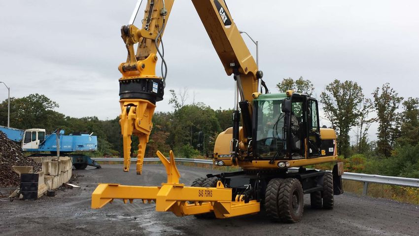
EXTREME                                              ™

                                         Auto Processor
                                             Excavator Attachment
                                             ==================
                                          Manual v17
USA Patents: D672,369 ; D704,752 ; D740,861, 9,211,832 ; D747,170 ; 8,414,704 ; D779,564; D779,565,
                               9,414,704 & Other Patents Pending

 SAS/op/proc/forks/op manuals/Ex/EXTREME MANUAL v17.pub 5/19/2021   Page   © 2014-2021 S.A.S. of Luxemburg, LLC.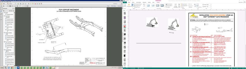
SERIAL NUMBER LOCATIONS (PAGE 2)
                                             SAS™ EXTREME™ AUTO PROCESSOR

      Local Distributor or Supplier Name ____________________ Phone ___________________
      Locate serial numbers and model numbers on SAS EXTREME Auto Processor Attachment..
      Note reference below. Providing this information when contacting your local Distributor,
         Supplier, Service Representative, or SAS will improve accuracy and level of service.

      SAS EXTREME
      Head Assembly                                                           SAS EXTREME

      Model………..._________                                                    Rotator Only:
      Serial Number _________                                                 Model:_______________
                                                                              S/N:    _______________

                                                                              PATENTED JAWS
                                                                              & patented tips

      SAS EXTREME Hold Down Arm Assembly...……...Model…………______________
      SAS EXTREME Hold Down Arm Assembly...……...Serial Number ______________

                                                                                   PATENTED
                                                                                 WIRE STRIPPER

             S.A.S. of Luxemburg, LLC. 133 Center Drive Hwy 54, PO Box 260, Luxemburg, WI 54217 USA
              Phone: 920-845-2307 • 1-877-SAS-FORK • Fax: 920-845-2309 • Web: www.sasforks.com

SAS/op/proc/forks/op manuals/Ex/EXTREME MANUAL v17.pub 5/19/2021   Page 2   © 2014-2021 S.A.S. of Luxemburg, LLC.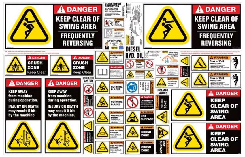
TABLE OF CONTENTS (PAGE 3)
                                             SAS™ EXTREME™ AUTO PROCESSOR
      Serial Number Location Reference…………………………………………….                                                    Page 2
      Limited intended use of this equipment………………………………………..                                               Page 3
      Introduction Letter………………………………………………………………..                                                         Page 4
      General Safety Guidelines……………………………………………………...                                                      Page 5 - 7
                                  Specific Notices CE ……………………………………..                                      Page 7
                                  Emergency STOP Function…………………………….                                       Page 7
                                  Safety Labels ……………………………………...…….                                        Page 8
      Installation Guidelines……………………………………………………………                                                        Page 9 - 14
                                  Optional Hold Down Hinge & Hydraulics Parts List                          Page 12 –13
                                  Pressure & Flow Settings Required…………………….                                Page 14
      Maintenance: …….. Torque intervals ………………………………………….                                                  Page 15
                                  Grease rotator & grapple ………………………………..                                   Page 16
      Pre-operation: ……. Checklist guide …………………………………………….                                                 Page 17
                                  Daily checklist………..………….…………………………                                       Page 18
                                  Determining Lift Capacity…………………………………                                    Page 19-20
      Operation Guidelines ……………………………………………………………..                                                        Page 21
      Parts lists……………………………………………………………………………                                                              Page 22-27
                                  Hold down arm ( EX25, EX30 & EX35 )………………...                              Page 12
                                  Claw tips            ( EX25, EX30 & EX35 )………………...                       Page 22
                                  Grapple head          ( EX25 v3, v4, v5    F5343 & higher)…               Page 23
                                                        ( EX30 v1………… F5902 & higher)…                      Page 28
                                                        ( EX35 v3………….F5764 & higher)…                      Page 29
                                                         (                                          .       Page 24
                                  Rotator Parts        ( EX25 F5692&UP,EX30 F5902&UP,EX35 F5764&UP ) Page 25-26
                                  Wire Stripper……………………………………………….                                          Page 27
      Limited warranty……………………………………………………………………                                                            Page 30
      CE Declaration of Conformity……………………………………………………                                                      Page 31
      LIMITED INTENDED USE OF THIS EQUIPMENT:
         SAS EXTREME™ Auto Processor excavator attachment is designed break recyclable scrap materials from
         end of life cars and trucks. Materials removed from cars and trucks will be damaged. Some excavators may
         require modification to pressures, valves, cylinders, reinforcement of x-frame, or other modifications for installa-
         tion and to operate in a desirable manner. This attachment is considered a non-OEM attachment and has not
         been approved by any specific excavator manufacturer. Customer is responsible to read the excavator’s manu-
         al and warranty documents, if any, and identify any impact installation and use of this attachment may have on
         the excavator’s warranty. Read this manual completely before installation or use.

        S.A.S. of Luxemburg, LLC. 133 Center Drive Hwy 54, PO Box 260, Luxemburg, WI 54217 USA
         Phone: 920-845-2307 • 1-877-SAS-FORK • Fax: 920-845-2309 • Web: www.sasforks.com

SAS/op/proc/forks/op manuals/Ex/EXTREME MANUAL v17.pub 5/19/2021      Page 3            © 2014-2021 S.A.S. of Luxemburg, LLC.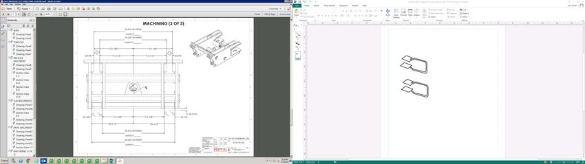
INTRODUCTION LETTER (PAGE 4)
                                             SAS™ EXTREME™ AUTO PROCESSOR
           TO THE OWNERS, MANAGERS, AND OPERATORS OF EXCAVATORS
                EQUIPPED WITH SAS™ EXTREME™ AUTO PROCESSOR
     Safety is the most important issue in the workplace. Observing safety guidelines, equipment
     capacities and using common sense will provide a work environment that is safe and efficient
     for employees, management and customers. It is important that you and your operators read
     and understand the information included in this manual prior to use of this equipment.

     Safety warnings are highlighted through out this manual. Understanding the significance of
     these symbols is important. The following is a definition of each symbol you will encounter in
     this manual:

                                The Symbol is intended to draw your attention to important safety
                                information, hazard or precaution.

                                The Danger Symbol indicates a hazardous situation that if not avoided will
                                result in serious injury or death

                                 The Warning Symbol indicates a hazardous situation that if not avoided
                                 could result in serious injury or death

                                 The Caution Symbol indicates a hazardous situation that if not avoided
                                 could result in minor injury or potential property damage

                        The Notice Symbol indicates worst credible severity of harm is property
                        damage.
                        The following information presented in this Operator Manual for SAS
     FORKS™ is intended to be a guide only, and is not meant to encompass all issues that may
     need to be addressed for your particular type of business operation.

     If you encounter additional information that would be helpful to us, or others, please contact us.

     Thank you for your business,
     SAS LLC.                                                  Phone:                       Email:
     S.A.S. OF LUXEMBURG, LLC.                                U.S.A. Dial: 920-845-2198     buyit@sasforks.com
     133 Center Dr Hwy 54 · PO Box 260                        International: 00+1+920-845-2198
     LUXEMBURG, WI 54217 U.S.A.

      ·Proprietary Rights: All designs and other proprietary rights provided by S.A.S. of Luxemburg, LLC. to Buyer
      are to remain the property of S.A.S. of Luxemburg, LLC., and Buyer shall honor all proprietary legends. Notice:
      The SAS FORKS™, this operator manual, www.sasforks.com web site, the pictures, content, designs, forks,
      and likeness of such, are property of S.A.S. of Luxemburg, LLC. and are protected under all applicable Copy-
      right, Trade Mark, Trade Dress, Patents and/or Pending Patent.
          USA Patents: D672,369 ;D704,752 ; D740,861; D779,564; 9,815,128; D779,565; 9,211,832; 9,414,704; D747,170
       No information, pictures, designs, products, features, or forks may be duplicated in part, entirety, or in likeness.

             S.A.S. of Luxemburg, LLC. 133 Center Drive Hwy 54, PO Box 260, Luxemburg, WI 54217 USA
              Phone: 920-845-2307 • 1-877-SAS-FORK • Fax: 920-845-2309 • Web: www.sasforks.com

SAS/op/proc/forks/op manuals/Ex/EXTREME MANUAL v17.pub 5/19/2021       Page 4          © 2014-2021 S.A.S. of Luxemburg, LLC.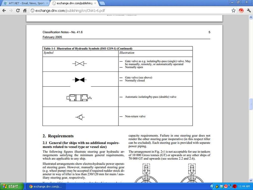
GENERAL SAFETY GUIDELINES (PAGE 5)
                                            SAS™ EXTREME™ AUTO PROCESSOR
  Installation & operation of equipment should only be performed by qualified and trained individuals. All per-
  sons operating or working in the area of operation should read this manual. A copy of this manual should
  be kept with the equipment. A qualified operator will operate the machine safely in accordance with, and:
      • Understand the written instructions supplied by the manufacturer of the device, the manufacturer of
          the excavator, all company rules and any applicable OSHA or regulatory governing body regulations.
      • Completed training including actual operation of the device and excavator to which it is attached.
      • Know and follow the safety rules and regulations of the jobsite.

                              Operation of equipment by un-qualified or un-trained individuals can result in seri-
                              ous injury or death. All operators must be properly trained prior to operation.

                              Not designed to be operated in an explosive environment. Only use this equipment
                              in well ventilated areas, a sufficient distance away from flammable or explosive gas-
                              es, liquids or substances to avoid risk of ignition. Operating in an explosive environ-
                              ment may cause an explosion and fire, resulting in injury, death, property damage.

                              Serious bodily injury, death and property damage can caused by an operator that is
                              under the influence of drugs or alcohol (of any type, illegal, prescribed or over the
                              counter) due to impaired operator judgment. Do not operate when impaired.
                              Consult your physician before operation of this equipment while on medication.

                              Inspect the device and perform all preventative maintenance before operation at the
                              start of every work shift. Failure to perform inspections or proper maintenance can
                              result in equipment failure resulting in serious injury or property damage.

                              This equipment is operated by high pressure hydraulics. Hydraulics are a stored
                              power source and as such must be treated as energized at all times. Be certain
                              pressure has been relieved prior to handling, inspecting or performing maintenance
                              on this unit. Follow lockout tag out procedures and release all stored energy before
                              servicing equipment. Failure to release energy or disable hydraulic energy can re-
                              sult in serious injury or death. High pressure fluids can also discharge at great ve-
                              locity and cause injection into skin. Wear safety glasses and appropriate gloves
                              while inspecting, operating and maintaining this equipment.

                              This equipment has numerous moving components. Operate only from the cab
                              equipped with safety glass windshield and adequate protective steel guard while
                              seated and wearing a safety belt. Be aware of potential pinch points and keep clear
                              during operation, inspection and maintenance. Pinch points exist between grapple
                              attachment jaws, cab swing, hold down arms and others, failure to keep clear while
                              in operation can result in serious injury or death.

                              Do not exceed posted weight limits on equipment. Review ‘Determining Lift Capacity’
                              section within this manual, lift capacity placards on machine, and within the machine’s
                              OEM operator manual. Exceeding rated load limits will result in equipment damage,
                              loss of steering control, machine tip over, serious injury or death.

             S.A.S. of Luxemburg, LLC. 133 Center Drive Hwy 54, PO Box 260, Luxemburg, WI 54217 USA
              Phone: 920-845-2307 • 1-877-SAS-FORK • Fax: 920-845-2309 • Web: www.sasforks.com

SAS/op/proc/forks/op manuals/Ex/EXTREME MANUAL v17.pub 5/19/2021   Page 5          © 2014-2021 S.A.S. of Luxemburg, LLC.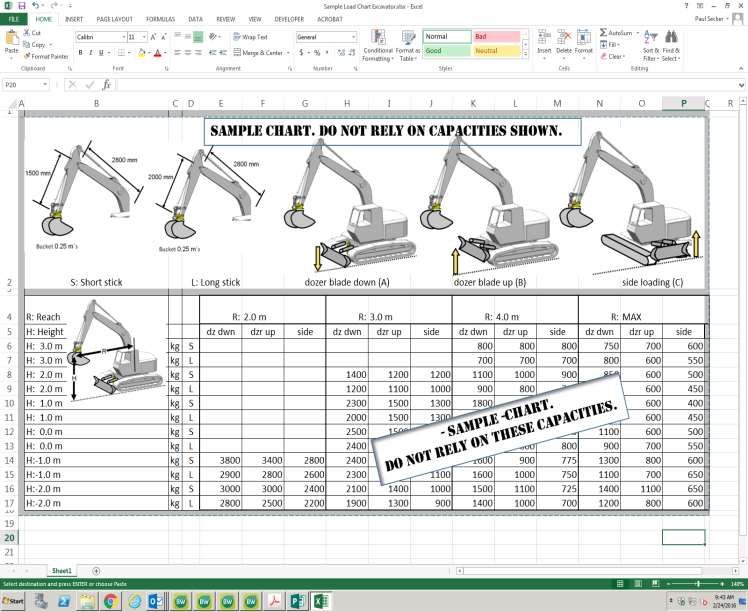
GENERAL SAFETY GUIDELINES (PAGE 6)
                                            SAS™ EXTREME™ AUTO PROCESSOR
        PROTECTIVE EQUIPMENT
                     • Safety glasses with side shields              ● Leather gloves
                     • Work boots with heavy sole and safety toes    ● Hard hat
                     • Fire extinguishing equipment                  ● Adequate spill kit, oil dry etc.
                     • Other such safety equipment to protect personnel from injury.

                              Puncture or cut injuries may occur if contact made with sharp objects. Sharp
                              objects are present from breaking materials out of scrap cars. Avoid contact.

                              Do not work under grapple claws, hold down, or any object lifted by this equip-
                              ment. An unexpected movement, shift in the object, or hydraulic failure may
                              cause claw, hold down, or object drop. Serious injury or death may occur.

        PERSONNEL TRAINING
                    Prior to installation or use of this equipment all personnel must review this operator
                    manual, excavator manufacturer’s manual and other pertinent safety manuals and be
                    trained by qualified personnel. All hazards must be identified to ensure personnel
                    avoid these hazards. Signed documentation certifying individual training has been
                    completed is a must. Periodic retraining is recommended. Failure to follow Manufac-
                    turers recommendations can result in serious injury and property damage.

        SITE PREPARATION & CLEAR OPERATING SPACE RECOMMENDED
                     • The Extreme™ Auto Processor should only be used in areas that are equipped
                        with proper fluid containment measures, to ensure capture and containment of
                        residual fluids in accordance with any and all environmental regulating body.
                     • Operation area must be sufficiently clear of buildings and overhead power lines.
                     • No Smoking, Safety Glasses & Hard Hat Required signage is recommended.
                     • Provide adequate space around this equipment to ensure all persons are kept at
                        least 15 Meters (50 feet) away from the equipment and cars being moving by it.

        VEHICLE PREPARATION PRIOR TO USING THE EXTREME™ AUTO PROCESSOR
                     • Prior to use of this attachment, remove all batteries, gasoline, diesel fuel, all
                       types of fuels, mercury switches, air conditioning Freon, engine oil, transmission
                       fluid, antifreeze and other fluids.
                     • Engines, transmissions, and other components will be damaged, and only be
                       suitable for metals recycling, not as cores or resalable operable parts.

                              Vehicles contain several hazardous elements that pose explosion, release of
                              toxic gas, and fire hazards, such as gasoline and electric batteries containing
                              battery acid, lithium-ion and other battery materials. Cars may have batteries
                              in multiple locations, some obvious and some hidden. Be sure all liquids and
                              batteries are safely removed prior to using EXTREME™ Auto Processor.
                              Failure to remove may result in explosion, release of toxic gas, fire & injuries.
                              Keep adequate fire suppression equipment accessible and persons trained on
                              operation.
             S.A.S. of Luxemburg, LLC. 133 Center Drive Hwy 54, PO Box 260, Luxemburg, WI 54217 USA
              Phone: 920-845-2307 • 1-877-SAS-FORK • Fax: 920-845-2309 • Web: www.sasforks.com

SAS/op/proc/forks/op manuals/Ex/EXTREME MANUAL v17.pub 5/19/2021   Page 6      © 2014-2021 S.A.S. of Luxemburg, LLC.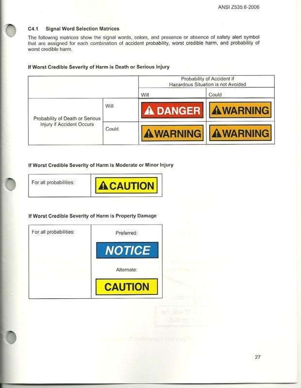
CE SPECIFIC NOTICES (PAGE 7)
                                             SAS™ EXTREME™ AUTO PROCESSOR
                              EMERGENCY STOP FUNCTION
                              To immediately stop the motion of this equipment:
                                   1. Operator is to release all joystick button(s).
                              Additional secondary measures to immediately stop the motion include:
                                   2. Moving excavator’s auxiliary hydraulic 3rd spool lever to neutral position
                                   3. Turn off ignition key of excavator to shut off engine
                              All three emergency stop options stop flow of hydraulic fluid. See excavator manufac-
                              turer’s operator manual to identify proper controls & functions prior to use.

                              Even after emergency stop function is followed, there is residual stored hy-
                              draulic pressure in the system. See following:

                               THIS EQUIPMENT IS OPERATED BY HIGH PRESSURE HYDRAULICS.
                               Hydraulics are a stored power source and as such must be treated as energized at
                              all times. Be certain pressure has been relieved prior to handling, inspecting or per-
                              forming maintenance on this unit. Follow lockout tag out procedures and release all
                              stored energy before servicing equipment. Failure to release energy or disable hy-
                              draulic energy can result in serious injury or death. High pressure fluids can also dis-
                              charge at great velocity and cause injection into skin. Wear safety glasses and appro-
                              priate gloves while inspecting, operating and maintaining equipment.

                              STAY CLEAR
                              • Do not lift persons with this equipment. Not intended to lift people
                              • Always maintain a safe distance away from this equipment.
                              • Do not go near or under this equipment or any object lifted by this
                                equipment. Failure to stay clear will result in injury or death.
                              • Refer to and follow all additional safety information in excavator
                                manufacturer’s operator, safety and service manuals.

                              POWER FAILURE
                              In the event of electrical or hydraulic supply failure from the excavator occurs, the
                              equipment will stop further motion. Under normal circumstances the equipment is not
                              expected to drop a load. The symbol at the left indicates the hydraulic controls on this
                              equipment are normally closed. Thus without electrical power the gate valves are
                              closed, in essence halting further movement. See excavator manufacturer’s oper-
                              ator manual to identify actual operation during power failure mode prior to use.

                              SOUND
                              This equipment does not emit more than 70dba.

                              VIBRATIONS
                              This equipment does not transfer vibrations in excess of 2.5m/s2.

                              OPERATING TEMPERATURE
                              Equipment is best suited to operate in temperatures 0°C to 32°C (32°F to 90°F )
                              with minimum temperature –30°C (–23°F) and maximum temperature 65°C (150°F)

             S.A.S. of Luxemburg, LLC. 133 Center Drive Hwy 54, PO Box 260, Luxemburg, WI 54217 USA
              Phone: 920-845-2307 • 1-877-SAS-FORK • Fax: 920-845-2309 • Web: www.sasforks.com

SAS/op/proc/forks/op manuals/Ex/EXTREME MANUAL v17.pub 5/19/2021    Page 7         © 2014-2021 S.A.S. of Luxemburg, LLC.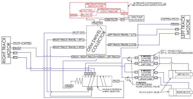
SAFETY LABELING (PAGE 8)
                                             SAS™ EXTREME™ AUTO PROCESSOR

   SERIAL NUMBER (Stamped in steel)
                                                                                   LABEL 2 (BOTH SIDES)
   LABEL 1

   LABEL 2 (BOTH SIDES)

   LABELS 3,4,5

                                                                             PATENTED JAWS
                                                                                   &
                                                                             patented tips

                                                     Label Description         Quantity      Label reorder #
                                  LABEL 1:           PRODUCT ID PLATE              1   ID PLATE CE-EX-V5

                                  LABEL 2:           KEEP BACK 15 METERS (50 FT)   2   W-LAB-STAYBACK50FT

                                  LABEL 3:           KEEP AWAY MOVING PARTS        1   W-LAB-WARNING-PINCH

                                  LABEL 4:           READ EQUIPMENT MANUALS        1   W-LAB-READ-504060

                                  LABEL 5:           HIGH PRESSURE HYDRAULICS1 1       W-LAB-PRES-503600

                                  LABEL 6:           STABILITY LABEL FOR CAB       1   W-LAB-EX-STABLE-1

             S.A.S. of Luxemburg, LLC. 133 Center Drive Hwy 54, PO Box 260, Luxemburg, WI 54217 USA
              Phone: 920-845-2307 • 1-877-SAS-FORK • Fax: 920-845-2309 • Web: www.sasforks.com

SAS/op/proc/forks/op manuals/Ex/EXTREME MANUAL v17.pub 5/19/2021    Page 8         © 2014-2021 S.A.S. of Luxemburg, LLC.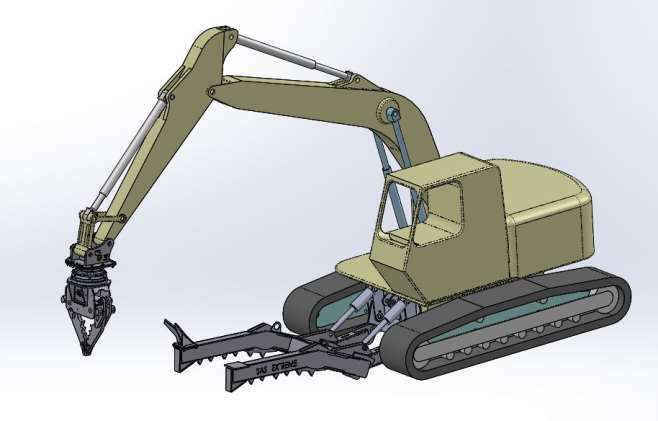
INSTALLATION: PREPARATION (PAGE 9)
                                             SAS™ EXTREME™ AUTO PROCESSOR
    ADVANCE PREPARATION BEFORE ARRIVAL & INSTALLATION OF EXTREME AUTO PROCESSOR
      • Review this operator manual. Review operator, safety & service manuals of excavator manufacturer.
    Items you need to obtain before arrival of Extreme™ Auto Processor:
      • Excavator must have two bi-directional auxiliary hydraulics at the end of the stick with cab controls.
      • If hold down arm is a component, excavator must hydraulic circuit on lower x-frame (or dozer)
      • Hydraulic fluid (specific for your machine). Identify fluid check and fill points.
      • Identify and obtain needed hydraulic hose quick connections on your machine and fitting required.
      • Locate supplier to make hydraulic hoses. Minimum recommend 19 mm (3/4”) diameter, 34 Mpa
         (5,000 PSI) hoses and fittings once proper length is determined during installation.
    Tools your mechanic may need for installation:
      • Sockets, wrenches, large adjustable wrench, large rubber hammer, hydraulic bottle jack, grease gun
    Service to do on your excavator in advance:
      • Have maintenance personnel replace hydraulic system filters & fluids (as needed)
      • Pressure and flow test. Have pressure results available. Set pressures:
           Grapple: Not to exceed: 130 L/m ( 35 gpm ) & 31 MPa, 350 Bar (4,500 psi)
           Rotator: Not to exceed: 40 L/m ( 10 gpm ) & 25 MPa, 250 Bar (3,600 psi)
      • Inspect pins & bushings in arm and dozer blade for wear (replace as needed)
      • SAS has no responsibility as to performance of excavator’s hydraulic system with this attachment.
    Available for training:
      • Designate an area (i.e. where it is safe to run equipment) and an employee to operate unit
      • Designate operator who can read and speak English, if SAS staff onsite to assist your mechanic.
                           Installation Hazards (Additional details covered elsewhere in this manual):
                           •Pinch & crush points, High pressure hydraulics, Stored pressure, Skin injection risk
                           •Installing this Extreme Head & Hold Down Assembly will change lifting dy-
                           namics & likely reduce lift capacity and reduce stability of the excavator.
      •Installer and operator must use caution in establishing reasonable lift capacities. Consider Head &
       HDA attachment weights and excavator manufacturer’s manual guidance. These hazards may cause
       equipment damage, injury or death. Only qualified persons should complete installation.

  COMPONENT IDENTIFICATION
                                                    STICK
                                                    MOUNT
                                                                              INSTALLATION           WIRE
     HYDRAULIC                                                                LIFT EYELETS           STRIPPER
     ROTATOR

        HEAD                                                   HOLD DOWN
    ASSEMBLY                                                    ASSEMBLY
     “HEAD ”                                                       “HDA”

                                                  CLAWS

          PATENTED JAWS & tips
             S.A.S. of Luxemburg, LLC. 133 Center Drive Hwy 54, PO Box 260, Luxemburg, WI 54217 USA
              Phone: 920-845-2307 • 1-877-SAS-FORK • Fax: 920-845-2309 • Web: www.sasforks.com

SAS/op/proc/forks/op manuals/Ex/EXTREME MANUAL v17.pub 5/19/2021     Page 9       © 2014-2021 S.A.S. of Luxemburg, LLC.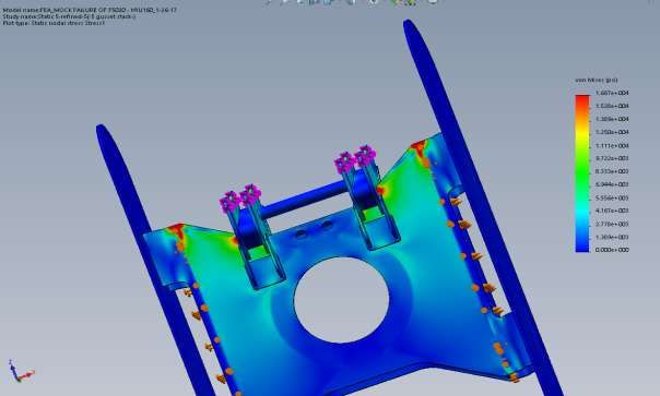
INSTALLATION: PREPARATION (PAGE 10)
                                            EXCAVATOR FRAME REINFORCEMENT
   POTENTIAL X-FRAME REINFORCEMENTS TO CONSIDER:
   Excavator OEM x-frame brackets which mount OEM dozer blade may not provide sufficient distribution of
   loads from SAS Extreme Hold Down Arm attachment & may result in x-frame & bracket structural failure.
   ●Careful consideration of this information will reduce the likelihood of x-frame & x-frame bracket failure.
   ●Operational advice: Minimize the amount of down force applied when restraining the car, specifically,
   avoid pushing down to the extent that the front of the excavator is lifted and suspended.
   ●This document is not authorization to modify excavator x-frame, it is intended to provide a guide for con-
   sideration of reinforcements for Customer, OEM, OEM authorized equipment tech., & professional welder.
           NOTICE: Any reinforcement work may cause Excavator OEM warranty, if any, to be void.
   ●Any reinforcement/modification of x-frame may cause other unintended cracking or damage. SAS is not responsible
   for reinforcement installation or performance, or resulting issues, if any.
   SAS Limited Warranty applies only to SAS manufactured components, not excavator, x-frame or x-frame brackets.

 Intent is to extend the force back further on x-frame where there is internal support to dissipate the loading forces.
 Reference:        1 - OEM hinge base plate existing                5 - NEW lower base plate expansion (two)
                   2 - NEW hinge base plate expansion (two)         6 - NEW lower load rib extension (four)
                   3 - NEW inner vertical load rib extension (two) 7 - NEW mid hinge frame tie in plate (one)
                   4 - NEW outer vertical load rib extension (two)
                            Upper view                                               Lower view

                               3     4
                         1 2

                                                                                                         5 6 7

                                     4                                                    7
                                     3
                                     2

                                     1
                                                                                                  5
                                                                                                  6

                                           Welding can damage excavator electronics.
                                      Read excavator manufacturer’s manual before welding.
 High pressure hydraulics. Stay clear of pinch points to avoid serious injury. Relieve pressure prior to work.
 Follow safety precautions in SAS EXTREME Auto Processor Manual prior to work.               www.sasforks.com/safety

SAS/op/proc/forks/op manuals/Ex/EXTREME MANUAL v17.pub 5/19/2021     Page 10           © 2014-2021 S.A.S. of Luxemburg, LLC.
INSTALLATION: HOLD-DOWN ASSEMBLY (PAGE 11)
SAS™ EXTREME™ AUTO PROCESSOR
INSTALLATION OF SAS™ EXTREME™ AUTO PROCESSOR HOLD DOWN ASSEMBLY (HDA):
INSTALLATION SHOULD BE COMPLETED BY AN EXPERIENCED HEAVY EQUIPMENT MECHANIC
1. Remove existing dozer blade. Inspect pins and bushings. Replace as needed.
2. Hold Down Assembly (HDA) weight approximately 1,620 kg ( 3,575 LB ).
Eyelets in center of HDA is balance point. If excavator is sufficiently rated to
lift such, align stick with lifting eyelets. Using safe and adequately rated rig-
ging chains, keeping all persons clear, lift HDA off pallet. Move away from
shipping pallet and place on ground with block in place which will allow upper
surface of HDA to be level.
3. HDA should be set level as shown below for staging. Drive excavator up to
HDA and align lower pivot holes in dozer blade mount on excavator with holes
“A” in HDA. Insert and secure pivot pins into assembly.
4. With pivot pins inserted and secure, slowly extend dozer blade hydraulic cylin-
ders to align holes in rod end of cylinder to lift holes “B” in HDA. Keep clear of
pinch points. Insert and secure pivot pins into assembly.
5. Replace any guarding that may have been removed during the removal of the
dozer blade assembly.
SAS has no responsibility as to performance of excavator’s Hydraulic system or
structural adequacy or durability with this attachment.
A B
block
GROUND
AFTER INSTALLATION, PRIOR TO OPERATION
1. Grease all pivot points with Stick and HDA resting on the ground and machine engine off.
2. Stay clear of pinch points. Slowly engage controls. Watch for interference. Stop if interference occurs.
a) Test up and down motions of HDA. Due to differences in machines and cylinder control valves,
if down cycle is not smooth, a jerking condition may occur.
Typically this can be rectified by installing simple flow control
valves on hydraulic lines which feed extend side of dozer
cylinders. (Indicated by arrows). (see Hold Down Parts list on
separate page). Two flow control valves are included in parts kit
with Qty 2, SAS Part No. HV-FLW-D-EF30S : Thread #8 NPT
Install flow control valves with fittings between car body frame
hose connection and hydraulic hose. Turn settings to near zero.
Test motion. Slightly open valves uniform amount. Retest. Repeat
until jerking occurs, then turn back to achieve smooth motion.
b) Test rotational clearance with HDA raised incrementally high-
er. Stay clear of pinch points, overhead electrical wires, and other structures, slowly and cautiously
rotate cab and counter weight visually checking for interference of lower cab and counter weight
with HDA lifted at highest level.
Stop if interference occurs & contact SAS FORKS with serial number for engineering assistance.
S.A.S. of Luxemburg, LLC. 133 Center Drive Hwy 54, PO Box 260, Luxemburg, WI 54217 USA
Phone: 920-845-2307 • 1-877-SAS-FORK • Fax: 920-845-2309 • Web: www.sasforks.com
SAS/op/proc/forks/op manuals/Ex/EXTREME MANUAL v17.pub 5/19/2021 Page 11 © 2014-2021 S.A.S. of Luxemburg, LLC.INSTALLATION: HINGE & HYDRAULICS (PAGE 12)
SAS™ EXTREME™ AUTO PROCESSOR
OPTIONAL: SAS SUPPLIED HINGE, HYDRAULIC DIVERTER BLOCK & CYLINDERS:
INSTALLATION SHOULD BE COMPLETED BY AN EXPERIENCED HEAVY EQUIPMENT MECHANIC
(Hoses are not included)
I.4 N, N.1, N.2
K, K.1,K.2, K.3
J, J.1, J.2
I, I.1, I.2, I.3 I.5
L, L.1, L.2, L.3
I.6
J, J.1, J.2
N
DESCRIPTION QTY PART NUMBER
[ I ] Cylinder for SAS Hinge & Hold Down 2 HY-CYL-5.0X11.25-5K
This cylinder is not for use with excavator which had existing dozer blade. Call excavator manufacturer.
I.1 Cylinder seal rebuild kit 2 HK-5.00-783-244
I.2 Cylinder pin bushing 4 W-B2.500X3.000X2.000
I.3 Cylinder pin grease seal 4 W-WIPER-2.5X3.0
I.4 Hinge (weldment) 1 0-EX-HGN- (Custom # per machine)
Read warnings on “Excavator Frame Reinforcement’ page & separate instructions provided with hinge.
I.5 Id plate 1 ID-PLATE-CE-EX (Specify serial no.)
I.6 Hold down arm (weldment)……………… 1 0-EX-HD- (Custom # per machine)
[J] Pin (cylinder to hold down: rod end) 2 1903-202VOL220-5112
J.1 Bolt (for cyl rod end pin) 2 WBOLT 0.375X425 GR8
J.2 Nut (for cyl rod end bolt)………………… 2 WNUT 0.375-16-GR8-NY
[K] Pin (cylinder to hinge: base end) 2 1904-006VOL220-5112A
K.1 Bolt (cylinder base pin) 2 WBOLT 0.625X1.50 GR8
K.2 Pin lock spacer (cylinder base pin)…….. 2 SPACER-0625-0000
K.3 Flat Washer (cylinder base pin)…………2 WASHER-F 0.625 GR8
[L] Pin (hold down to hinge: lower pivot) 2 1315TILT-3454 ASY
L.1 Bolt (lower pivot pin) 2 WBOLT 0.625X1.50 GR8
L.2 Pin lock spacer (lower pivot pin)………...2 SPACER-0625-0000
L.3 Flat Washer (lower pivot pin) 2 WASHER-F 0.625 GR8
[M] HYDRAULICS
These parts are not for use with excavator which had existing dozer blade. Call excavator manufacturer.
M.1 Flow valves (thread #8 NPT)…… 2 HV-FLW-D-EF30S
If jerking occurs during lowering Hold Down Arm (HDA), install flow valves on hydraulic lines
which feed extend side of both cylinders, adjust equally reduce flow to eliminate or reduce this issue.
M.2 Counter balance block (empty block) 2 HV-BLK-S-YEJ-S
M.3 Counter balance valve (valves for block) 4 HV-CB-S-CBPA20MNS050
After cycling the Hold Down Arm a number of times to eliminate air in lines, if Hold Down Arm does
not hold it’s positioning, install counter balance valve block with valves in line before each cylinder.
M.4 Pilot valve……………………..… 1 HV-BLK-F-DS70HP-1
See following page for additional information.
[N] CYLINDER GUARD (Only units with SAS hinge F5972 & UP) 2 1902-027
N.1 1/2” x 6 1/2” Hex bolt 4 WBOLT 0.500X6.50 GR8
N.2 1/2” Nyloc nut 4 WNUT 0.500-13-GR8-NY
SAS/op/proc/forks/op manuals/Ex/EXTREME MANUAL v17.pub 5/19/2021 Page 12 © 2014-2021 S.A.S. of Luxemburg, LLC.INSTALLATION: HINGE & HYDRAULICS (PAGE 13)
SAS™ EXTREME™ AUTO PROCESSOR
OPTIONAL: SAS SUPPLIED HINGE, HYDRAULIC DIVERTER BLOCK & CYLINDERS:
INSTALLATION SHOULD BE COMPLETED BY AN EXPERIENCED HEAVY EQUIPMENT MECHANIC
(Installation may impact or void machine OEM warranty, if any)
(Hoses are not included)
DESCRIPTION QTY PART NUMBER
M.4 Pilot Operated Selector Valve Block [‘Valve’]……………….. 1 HV-BLK-F-DS70HP-A
Locate ‘Valve’ for installation within protected area inside the x-frame belly.
Purpose: Divert fluid from right track to hydraulics to SAS Extreme hold down cylinders.
●Ports A & B are input Into ‘Valve’ which are pulled downstream of swivel/collector underneath the excavator that
would originally route to one drive motors for one of the tracks, SAS has always used the ‘right’ track hydraulics.
●Ports E & F are then routed to drive motor for right track in standard position.
●The high speed pilot line that originally runs to each the left and the right track drive motors is disconnected from
the motors and now only is routed to the pilot port on this ‘Valve’. This pilot line is typically the smaller of the two
small lines that run through the swivel/collector. This enables the 2 nd position of the ‘Valve’ to function when the
‘high speed’ function is actuated in the cab of the excavator.
●With pilot line pressurized, ports C & D are now live & will be routed to cylinders to position hold down up/down.
●’Drain line’ is final port on ‘Valve’, this will be need to be T’d into existing drain line that runs from each track drive
motor & back up through the swivel. This line is typically larger of two ‘small’ lines running through swivel/collector.
If arm operates as expected, keep OEM pilot source at ‘P?’ If track unexpectedly moves, cap off OEM pilot at P?,
? then install Alternate Pilot Feed (APF?), valve, drain & switch to connect to “Pilot In” rather than OEM pilot.
M.5 Valve Block [for Alternative Configuration]………………………………….1 HV-BLK-E-AT180585
Hydraulic Schematic ?
S.A.S. of Luxemburg, LLC. Phone: • 920-845-2307 • 1-877-SAS-FORK • Web: www.sasforks.com
SAS/op/proc/forks/op manuals/Ex/EXTREME MANUAL v17.pub 5/19/2021 Page 13 © 2014-2021 S.A.S. of Luxemburg, LLC.INSTALLATION: HEAD (PAGE 14)
SAS™ EXTREME™ AUTO PROCESSOR
INSTALLATION OF SAS™ EXTREME™ AUTO PROCESSOR HEAD ASSEMBLY:
INSTALLATION SHOULD BE COMPLETED BY AN EXPERIENCED HEAVY EQUIPMENT MECHANIC
1. Remove existing bucket and inspect pins and bushings.
Replace as needed.
2. Line up palletized head assembly & machine. Image (i).
Note: Head weight approximately:
Model EX-25 & 35: 1,300 kg ( 2,850 lb )
3. Lower stick of excavator down to line up with hole at top of
assembly and insert and secure pin “A” into head assembly.
(i)
4. With pin “A” secure in head assembly, lift assembly so that
only the tips of the head assembly are resting on pallet as
shown in image (ii). Align curl linkage to other hole in head
Assembly mount. Insert & secure pin “B” in head assembly.
5. Connect hydraulic hoses.
Hose specification 34 Mpa, 344 Bar (5,000 psi) Min. dia. 19 mm 3/4”
SAS has no responsibility as to performance of excavator’s hydraulic
system with this attachment.
Jaws (Grapple) connection (EX: v4 & v5 only)
Fittings: #12 BSP (thread in type) /or/
#16 CODE 62 (4 bolt type)
Flow (Maximum):
130 L/min (35 gpm) (ii)
Pressure (Maximum)
31 MPa, 310 Bar
(4,500 psi)
A
B
Rotator connection
(EX: v4 & v5 only)
Fittings: #8 BSP
Flow (Maximum)
40 L/min (10 gpm)
Pressure (Maximum)
25 MPa, 250 Bar (3,600 psi)
AFTER INSTALLATION PRIOR TO OPERATION
1. Grease all pivot points with Head and Hold Down resting on ground and machine engine off.
2. Read excavator manufacturer’s manual to identify control levers operation, method to stop mo-
tions, safety parameters related to operation of the excavator with any specialized attachment.
3. Stay clear of pinch points. Slowly engaging controls, test all motions of Head Assembly.
Watch for interference points and stop further motion if interference occurs.
S.A.S. of Luxemburg, LLC. 133 Center Drive Hwy 54, PO Box 260, Luxemburg, WI 54217 USA
Phone: 920-845-2307 • 1-877-SAS-FORK • Fax: 920-845-2309 • Web: www.sasforks.com
SAS/op/proc/forks/op manuals/Ex/EXTREME MANUAL v17.pub 5/19/2021 Page 14 © 2014-2021 S.A.S. of Luxemburg, LLC.PREVENTIVE MAINTENANCE (PAGE 15)
SAS™ EXTREME™ TORQUE INTERVALS
Set attachments on ground, turn off excavator, depressurize hydraulic supply to attachments, stay clear of pinch points during
greasing. Safe & proper daily maintenance will help ensure long term performance and prevent failures. Failure to follow pre-
ventive maintenance guidelines can result in equipment failure resulting in injury or property damage.
Visual Inspections: Frequency daily pre-operation inspection (or every 10 operating hours)
Re-Torque interval chart: After first 50 hours of operation & every 250 hours thereafter.
Replace Loose Bolt & Bolt on each side: During daily pre-operation inspection if any bolt
(specifically Ref. C, D, E, F, G) are found to be more than 80% out of stated tightening torque or require
more than 1/4 of turn to obtain required re-torque, install new bolt & adjacent bolts and set torque.
Ref. Thread Location # Torque Wrench Hour Interval
Bolts Spec Size
10 50 Every 12000
250 replace
bolts
A
A Metric Hoses to stick 4 70-78 ft-lb 1 - 3/8”
B
B Pins 2 Per OEM
C
C SAE Stick mount to stick 18 500 ft-lb 1 - 1/2”
adaptor
(Prior to s/n: F5909) Adaptor plate not used s/n F5909 & higher. D
D Metric Stick adaptor to 12 580 ft-lb Metric
rotator (v4 & v5) 36 mm C
Prior to s/n:F5908 Bolts hidden location under stick mount. Remove stick mount to inspect annually.
s/n F5909 & higher Bolts are open and visible on top of stick mount. E
E SAE Rotator lower 30 160 ft-lb 15/16”
mount
F SAE Lower adaptor to 36 160 ft-lb 15/16”
clamp body (v4 only) F
G Cylinder hoses & 4 50 ft-lb 30mm:
fittings fitgs 1-3/16” G
H SAE Cylinder service 4& Hand tighten 9/16”
cover 4
I SAE Bolts, clip & pin 5 Hand tighten 15/16”
(head) H
J SAE Claw tips bolts 10 160 ft-lb 3/8” HEX
& 15/16
Socket
K SAE Hold down bolts & 4 Hand tighten 9/16”
pins
Replace all bolts every 12,000 hours: Specifically Ref. C, D, E, F
Apply Blue Loctite 243 to bolts Ref. C, D, E, F when replacing.
S.A.S. of Luxemburg, LLC. 133 Center Drive Hwy 54, PO Box 260, Luxemburg, WI 54217 USA
Phone: 920-845-2307 • 1-877-SAS-FORK • Fax: 920-845-2309 • Web: www.sasforks.com
SAS/op/proc/forks/op manuals/Ex/EXTREME MANUAL v17.pub 5/19/2021 Page 15 © 2014-2021 S.A.S. of Luxemburg, LLC.PREVENTIVE MAINTENANCE (PAGE 16)
SAS™ EXTREME™ GREASING
Place grapple on firm level surface, turn off machine & avoid pinch points.
Lubricating the rotating grapple head (For models: SAS EXTREME EX-25 v4 & v5 )
Lubricate the SAS EXTREME Auto Processor rotating grapple head daily. Use this opportunity to closely
inspect the pins and pin retaining hardware and conduct necessary repairs.
Recommended grease:
Brand Raceway Grease Brand Pin Grease
Mobil Mobilux EP2 Mobil Centaur Moly EP2
1/14/2019 Indexator 2014 Service InfoSheet (11/4/2016 Per Eric @ Harlon Oil)
Shell Gadus S2 V220 2 Mobil Mobilegrease CM-P
Castrol Spheerol EPL2 Comparable Comparable
Lubrication interval chart
Indexator XR600 Raceway EXTREME head Grapple Pins EXTREME hold down Pivot Pins
Quantity of nipples 6 nipples Quantity of nipples 5 nipples Quantity of nipples 4 nipples
Every 40 hours Apply to all nipples to Every 10 hours* 4 pumps Every 10 hours* 2 pumps
operating* obtain even amount
grease appears Every 40 hours* 4 pumps Every 40 hours* 4 pumps
around the entire
bearing seal *operating hours
Grease nipple locations Grease
Grease
√ Bolt √ Bolt
√ C Clip √ C Clip
√ Pin √ Pin
√ Bolt(s)
√ Pin
√ Bolt(s)
√ Pin
√ Bolt √ Bolt
√ Pin √ Pin
√ Bolt √ Bolt(s)
√ C Clip √ Pin √ Bolt(s)
√ Pin √ Pin
JAWS, WIRE STRIPPER & HOLD DOWN ARM PATENTED
S.A.S. of Luxemburg, LLC. 133 Center Drive Hwy 54, PO Box 260, Luxemburg, WI 54217 USA
Phone: 920-845-2307 • 1-877-SAS-FORK • Fax: 920-845-2309 • Web: www.sasforks.com
SAS/op/proc/forks/op manuals/Ex/EXTREME MANUAL v17.pub 5/19/2021 Page 16 © 2014-2021 S.A.S. of Luxemburg, LLC.PRE-OPERATION CHECKLIST (PAGE 17)
SAS™ EXTREME™ AUTO PROCESSOR
READ & FOLLOW SAFETY INFORMATION IN ORIGINAL EXCAVATOR MANUFACTURER’S
OPERATOR, SAFETY AND SERVICE MANUALS. This checklist is limited to pre-operations
inspection focused on Extreme Head and Hold Down Arm assemblies (HDA).
Additional inspection points will be recommended in the excavator manufacturer manuals.
Failure to follow instructions and precautions noted in excavator manufacturer’s
manuals and this manual can result in serious damage to equipment and/or result
in injury or death.
Use caution while inspecting. Be aware of:
• Pinch points (and additional risks covered throughout this manual)
• High pressure hydraulic fluids or stored energy
• Location of other individuals in the work area
Prior to conducting inspection;
• Stick and Head assembly must be resting on firm level ground.
• Hold Down Assembly (HDA) must be resting on firm level ground.
• Excavator must be parked on firm level ground
• Excavator engine must be turned ‘off’
EXTREME AUTO PROCESSOR ATTACHMENT INSPECTION POINTS:
Head to stick fastening pins Single direct stick mount Stick mount & stick adaptor
• Check rotator to stick mount bolts s/n F5909 & up s/n under F5908
• Check pins for properly secured
• Check stick mount for cracks
Rotator
• Check bolts fastening rotator to clamp body
• Check rotator for cracks
• Check for leaks or damage on hoses.
Clamp body
• Check for damaged pins, pin retention
hardware or misaligned pins
• Check clamp body for cracks
Claws & tips
• Check claws for cracks
• Check claw tip bolts
Hold Down Assembly (HDA)
• Check all pins for properly secured
• Check HDA for cracks
• Check wire stripper for loose or missing bolts
Excavator x-frame inspection
• Look from bottom up & or cracks around hinges
Operator cab
• Cab should have Roll Over Protection System
• Verify safety glass windshield in place
• Verify exterior steel guard is in place over front wind-
shield to protect operator.
Repair all problems before operation. Lock out / tag out excavator if defects present.
Repairs must only completed by authorized mechanic.
SAS/op/proc/forks/op manuals/Ex/EXTREME MANUAL v17.pub 5/19/2021 Page 17 © 2014-2021 S.A.S. of Luxemburg, LLC.DAILY PRE-OPERATION CHECKLIST (PAGE 18)
SAS™ EXTREME™ AUTO PROCESSOR
Set attachments on ground, turn off excavator, depressurize hydraulic supply to attach-
ments, stay clear of pinch points during greasing. Safe & proper daily maintenance will help
ensure long term performance and prevent failures. Failure to follow preventive mainte-
nance guidelines can result in equipment failure resulting in injury or property damage.
Item √ √ √ √ √ √ √ √ √ √
Stick pin & bolt
Stick pin & bolt
Stick mount bolts
Stick mount cracks
All Rotator bolts
Rotator cracks
R-Cyl bolt, clip, pin √ Bolt √ Bolt
L-Cyl bolt, clip, pin √ C Clip √ C Clip
√ Pin √ Pin
Main pivot grease
Main pivot grease
Main pivot pin, bolt
Main pivot pin, bolt
Clamp body cracks
√ Bolt √ Bolt
Parallel bar pin, √ Pin √ Pin
bolt, clip
R-Claw tip bolts √ Bolt
L-Claw tip bolts √ C Clip
Claw cracks √ Pin
Hold arm bolt, pin
Hold arm bolt, pin √ All Fasteners
√ Bolt(s)
Hold arm cracks √ Pin
Wire stripper bolts √ Bolt(s)
√ Pin
Machine x-frame
Structural cracks
Grease
Date
Machine hours √ Bolt(s)
√ Pin
√ Bolt(s)
√ Pin
Inspection by:
JAWS, JAW TIPS, WIRE STRIPPER
& HOLD DOWN ARM PATENTED
SAS/op/proc/forks/op manuals/Ex/EXTREME MANUAL v17.pub 5/19/2021 Page 18 © 2014-2021 S.A.S. of Luxemburg, LLC.DETERMINING LIFT CAPACITY (PAGE 19)
SAS™ EXTREME™ AUTO PROCESSOR
READ & FOLLOW SAFETY INFORMATION IN ORIGINAL EXCAVATOR MANUFACTURER’S
OPERATOR, SAFETY AND SERVICE MANUALS.
Excavator will handle loads differently than with the original dozer blade & bucket.
The purpose of this document is to describe tmethod of load rating and operating limitation parameters
of Extreme auto processor as indicated on operating data plate of device.
On this product, SAS Forks installs a data plate on the product which specifies ;
■ Product model
■ Product serial number
■ Product weight
■ Product production date
■ Notice to refer to Excavator OEM positional lift chart and make appropriate reductions in permissible lift
capacities to offset any differential in the original rated attachment, if any, and the weight of the Product,
the Extreme Head Assembly.
It is important to note that the actual load (lift) ratings of the product are impacted by multiple factors
in which the operator is responsible to take into account and to reduce the weight of any potential
item to lift, to ensure machine remains stable, and does not tip. The below items are not a comprehensive
list, but these complex work variables must be taken into account by the operator to ensure
safe operation;
■ Ground or working surface stability
■ More unsafe: soft, unpredictable or variable surface compaction /vs/
■ More safe: solid surface
■ Positioning of excavator on such working surface
■ More unsafe: angled and tilted /vs/
■ More safe: flat & level
■ Proximity in which excavator is to work and materials to be lifted.
■ More unsafe: Extending lift arms and lifting /vs/
■ More safe: working close with minimum reach
■ Lowering and engagement of outriggers to working surface
■ More unsafe: Outriggers removed and/or not engaged to ground /vs/
■ More safe; Outriggers lowered fully and engaged with solid working surface.
■ Amount of hydraulic pressure operator allocates to the grapple of the Extreme product
■ More unsafe: Operator not providing sufficient hydraulic pressure to engage object lifted /vs/
■ More safe: Operator engages excavator’s hydraulic system to ensure secure grappling.
■ Lift capacity limitation of excavator, based on excavator’s OEM lift capacity chart
■ More unsafe: Not understanding parameters and assumes within excavator’s OEM chart /vs/
■ More safe: Clearly understand excavator’s OEM load chart, product weight, & parameters.
■ Strength and durability of the item being lifted. (This product is meant only to lift scrap metal,
never lift any good resalable product. Never lift any persons or any device holding any persons.
■ Prohibited & dangerous: Attempting to lift persons in any manner will result in injury or death.
■ More unsafe: Lifting items in such a manner that may rip or separate /vs/
■ More safe: Grapple items on heavy surface that provides a secure grip with Extreme grapple.
SAS/op/proc/forks/op manuals/Ex/EXTREME MANUAL v17.pub 5/19/2021 Page 19 © 2014-2021 S.A.S. of Luxemburg, LLC.DETERMINING LIFT CAPACITY (PAGE 20)
SAS™ EXTREME™ AUTO PROCESSOR
Establishing Load Ratings
The structure of the Extreme auto processor grapple head attachment is designed to lift a load that
meets or exceeds the excavator’s boom lift capacity, when hydraulic pressure of between 80% and
100% of maximum pressure per the label on Extreme grapple head attachment is supplied by the excava-
tor, the Extreme’s grapple mechanism to adequately engage the item lifted.
The lift limitations set forth by the excavator OEM (Original Equipment Manufacturer) must be reviewed
and understood by the operator. The excavator OEM operator manual or in cab label is expected to pro-
vide a chart with lifting capacities at a variety of lift positions, in accordance with ISO 10567:2007 The
operator must apply the weight of the Extreme grapple head assembly and interpret the excavator OEM
chart whereas the position of the dozer blade or stabilizers are considered to be off the ground to deter-
mine the permissible load.
Sample chart. This chart does not contain any valid lift capacities for any excavator equipped with an
Extreme auto processor attachment.
In accordance with typical excavator OEM lifting charts, with general reference to sample chart
above, positions that effectively reduce the load threshold at which tipping occurs, include:
●Lifting dozer blade, downriggers or Extreme hold down arm, as shown in sample illustration (B) or (C).
●Turning of excavator’s cab across tracks or wheels with the dozer up, shown in sample illustration (C).
●Extending the reach of the boom and stick.
Operator must identify load chart for specific excavator, not included herein, and use limits
per the chart which specifies ‘dozer up and side lift’ or ‘outriggers up and side lift’, and sub-
tract weight of Extreme grapple head assembly, to identify the net lift capacity permissible.
SAS/op/proc/forks/op manuals/Ex/EXTREME MANUAL v17.pub 5/19/2021 Page 20 © 2014-2021 S.A.S. of Luxemburg, LLC.OPERATION GUIDE (PAGE 21)
SAS™ EXTREME™ AUTO PROCESSOR
FOLLOW SAFETY INFORMATION IN EXCAVATOR Minimize amount of
MANUFACTURER OPERATOR MANUAL. down force applied
Be cautious, as working load capacities are determined. when restraining
Secure car down with Hold Down Arm. car. Avoid pushing down to extent that
Use jaws to pull and break out desired scrap metal. front of excavator is lifted and suspend-
ed. Excess stress can cause x-frame fail-
Tip over & crush
risk. Extreme
Head Assembly
may weigh more than the original bucket
which the excavator manufacturer in-
stalled, thus reducing the po-
tential lift capacity. Lifting
excess weight may cause tip
over, damage & injury or
death. Wear seat belt.
Move controls
slowly, not jerking
machine. Rough
or jerking motions may cause damage to
machine or Extreme attachment.
Electrocution and
crush risk if con-
tact made with electric power lines or
building structure.
Prior to rotating cab be sure Hold Down Arm is lowered against car or flat on ground.
Tip over risk.
Rotating machine
with hold down arm or any out-riggers
not in firm contact with ground or at-
tempting to travel with an elevated load,
may cause the machine to tip over.
To provide best stability prior to rotating
the cab, place hold down arm firmly
against ground or on car. Wear seat
belt.
Risk of claw contact
with cab & damage
and or injury to op-
erator if operator curls boom, stick, and jaws
in. Do not fully curl boom, stick, jaws in.
Avoid Head & wire
stripper contact
when rotating cab.
Damage may occur.
Multiple times during work day, complete several full rotations to circulate fresh fluid from tank to rotator.
If Hold Down Arm appears to sway to side or lift height becomes reduced it may indicate x-frame damage
SAS/op/proc/forks/op manuals/Ex/EXTREME MANUAL v17.pub 5/19/2021 Page 21 © 2014-2021 S.A.S. of Luxemburg, LLC.PARTS DIAGRAM (PAGE 22)
SAS™ EXTREME™ AUTO PROCESSOR
FITS ALL EX CLAWS W/REPLACEABLE TIPS
Quantity Quantity
One Tip Two Tips
Req.Tip-1 & Tip-2
1 2
5 10
5 10
5 10
5 10
2
3
1
4
5
PATENTed JAWS & JAW TIPS.
Pinch points will cause serve injury. Stay clear of pinch points at all times.
Only an authorized and experienced person should perform this work.
S.A.S. of Luxemburg, LLC. 133 Center Drive Hwy 54, PO Box 260, Luxemburg, WI 54217 USA
Phone: 920-845-2307 • 1-877-SAS-FORK • Fax: 920-845-2309 • Web: www.sasforks.com
SAS/op/proc/forks/op manuals/Ex/EXTREME MANUAL v17.pub 5/19/2021 Page 22 © 2014-2021 S.A.S. of Luxemburg, LLC.EX-25 PARTS DIAGRAM (PAGE 23)
SAS™ EXTREME™ AUTO PROCESSOR
15-26 TON EX-25 SERIAL NUMBER F5343 & UP
Pin Type R-3
R-3.3
R-3.4
R-3.5
N-4 & N-5
N, N-1, N-2, N-3
P-3.2
SAS
O-3
PATENTED
JAWS & tips
DESCRIPTION QTY PART NUMBER
[N] CLAW CYLINDER 1 HY-CYL-5.0X11.25-5K
N-1 CYLINDER SEAL REBUILD KIT 1 HK-5.00-783-244
N-2 CYLINDER PIN BUSHING…………………………………………. 2 W-B2.500X3.000X2.000
N-3 CYLINDER PIN GREASE SEAL 4 W-WIPER-2.5X3.0
N-4 HOSE KIT - EX25v4 only EXTEND & RETRACT HOSES 1 HY-EXTREME-KIT-V4
- EX25v5 (& V3) EXTEND & RETRACT HOSES…..1 HY-EXTREME-KIT
N-4.1 FITTING w/O-rings BETWEEN HOSE & ROTATOR (w/hose kit) 2 HY-12MBSPPX10MORF
N-4.2 FITTING w/O-rings BETWEEN HOSE & CYLINDER (w/hose kit) 2 HY-848-TTO-10X10
N-5 HOSE CLAMP-HOLDS HOSES UNDER ROTATOR 1 HY-CLAMP-.750-2HOSE
[O-3] CLAW ASSEMBLY W/TIP (FASTENED W/2 PINS: R-3.1, O-3.1) 1 EP-EX25-CLAW-LH-V3-3
O-3.1 PIN (CONNECTS CYLINDER ROD END TO CLAW) LH 1 1902-004-V3 ASY
O-3.2 BUSHING (1 REQUIRED FOR EACH CLAW PIVOT PIN).. 1 W-B3.002X3.505X6.437
O-3.3 GREASE ZERK (INSIDE BOTH ENDS OF PIN “0-3.1”) 2 WGREASE ZERK 1/4-28
O-3.4 REPLACEABLE CLAW TIP WITH 2 RIDGES……………… 1 EP-EXC-CLAW-TIP-2-V3
[P-3] CLAW ASSEMBLY W/TIP (FASTENED W/3 PINS: R-3.1, P-3.1, P-3.2) 1 EP-EX25-CLAW-RH-V3-3
P-3.1 PIN (CONNECTS CYLINDER BASE END TO CLAW) RH 1 1902-007-V3 ASY
P-3.2 PIN-PARALLEL BAR PIN - RH………………...…………….. 1 1902-008-V3 ASY
P-3.3 RETAINER BOLT FOR PINS 5 WBOLT 0.625X1.50 GR8
P-3.4 WASHER RETAINER BOLT………………………… 5 WASHER-F 0.625 GR8
P-3.5 PIN-LOCK SPACER 5 SPACER-0625-0000
P-3.6 C-CLIP RING………………………………………….. 3 MCC-98410A231
P-3.7 GREASE ZERK (INSIDE END OF PIN “P-3.2”) 1 WGREASE ZERK 1/4-28
P-3.8 BUSHING (1 REQUIRED FOR EACH CLAW PIVOT PIN).. 1 W-B3.002X3.505X6.437
P-3.9 REPLACEABLE CLAW TIP WITH 1 RIDGE 1 EP-EXC-CLAW-TIP-1-V3
P-3.10 TIP FASTENERS - QTY 5 PER TIP - QTY 10 TOTAL…….10 EP-EXC-CLAW-TFAST-V3
(3/4” X 2-1/4” SHOULDER BOLT, 3/4” WASHER, 5/8” WASHER & 5/8” LOCK NUT)
[Q-3] PARALLEL BAR (s/n F5343 & Higher) 1 EP-EX25-PBR-V31
[R-3] CLAMP BODY EX25 s/n F5720 & higher (include F5712) 1 EP-EX25-CBY-V5
EX25 s/n F5703 & earlier (include F5713, F5717) 1 EP-EX25-CBY-V3
R-3.1 MAIN CLAW PIVOT PIN 2 1901-011-V3-ASY
R-3.2 3” ID SHIM X 0.09375” THICK……………………… 4 W-SC-SHIM-.094
R-3.3 BOLT TO RETAIN MAIN CLAW PIVOT PIN 2 W BOLT 0.625X1.50 GR8
R-3.4 FLAT WASHER……………………………………… 2 WASHER-F 0.625
R-3.5 PIN LOCK SPACER 2 SPACER 0625-000
SAS/op/proc/forks/op manuals/Ex/EXTREME MANUAL v17.pub 5/19/2021 Page 23 © 2014-2021 S.A.S. of Luxemburg, LLC.EX-25, EX-30 & EX-35 PARTS (PAGE 24)
SAS™ EXTREME™ AUTO PROCESSOR
STICK MOUNT & ROTATOR
EX-25 S/N F5692 TO F5903 S.4 EX-25 S/N F5909 & HIGHER
EX-30 S/N F5902 S.3 EX-30 HIGHER THAN F5909
EX-35 S/N F5764 TO F5801 EX-35 HIGHER THAN F5909
S
S.1 S
T.1
S.5
T
S.2 U.1
U
V.1
Only
EX25v4
V
N-5
N-5 N-4.1
N-4 N-4.2
N-4.2
HY-848-TT0-10X10
HY-848-TT0-10X10 #10 MOFRX#10MORB
#10 MOFRX#10MORB
R-3
DESCRIPTION QTY PART NUMBER
[S] STICK MOUNT 1 EP-EX25-STK...BY MACHINE
S.1 BOLTS FOR STICK MOUNT 1”-8 X 3” GR8 18 WBOLT 1.00X03.00 GR8
RE-TORQUE PAGE REF: C (BLUE LOCTITE 243 & 500 FT-LBS)
S.2 NUTS FOR STICK MOUNT 18 WNUT 1.000-8 GR8
S.3 HOSE GUARD……………………………………………………….. 1 1901-065
S.4 HOSE GUARD BOLTS 2 WBOLT 1.00X03.50 GR8
S.5 HOSE GUARD NUTS 2 WNUT 1.000-8 GR8
[T] ADAPTOR (STICK MOUNT TO ROTATOR) v4,v5 (S/N: F5692 & UP) 1 EP-EX25-STK-INADPTR
T.1 BOLTS ADAPTOR TO ROTATOR M24-3.0X65 10.9 12 WBOLT 24MM
SEE RE-TORQUE PAGE 15 REF: D (BLUE LOCTITE 243 & 580 FT-LBS)
F5692-F5903 BOLTS ARE HIDDEN, MUST UNCOVER TO RETORQUE
[U] ROTATOR XR600 1 HR-ROTAR-N-XR600
EX25-v4 & v5 #F5692&up;EX30 #F5902&up;EX35-v3 #F5764&up
U.1 BOLTS ROTATOR TO LOWER MOUNT 5/8”-11 X 5” GR8 30 WBOLT 0.625x5.00 GR8
RE-TORQUE PAGE REF: E (BLUE LOCTITE 243 & 160 FT-LBS)
[V] CLAMP BODY ADAPTOR v4 (S/N F5692-F5717) (exclude F5712) 1 EP-EX25-CBY-ROTIND
V.1 BOLTS CLAMP BODY ADAPTOR 5/8”-11 X 2-1/2” GR8 36 WBOLT 0.625X2.50 GR8
RE-TORQUE PAGE REF: F (BLUE LOCTITE 243 & 160 FT-LBS)
SAS/op/proc/forks/op manuals/Ex/EXTREME MANUAL v17.pub 5/19/2021 Page 24 © 2014-2021 S.A.S. of Luxemburg, LLC.You can also read