Fabrication of microvascular constructs using high resolution electrohydrodynamic inkjet printing - IOPscience
←
→
Page content transcription
If your browser does not render page correctly, please read the page content below
Biofabrication

PAPER • OPEN ACCESS

Fabrication of microvascular constructs using high resolution
electrohydrodynamic inkjet printing
To cite this article: Fei Zheng et al 2021 Biofabrication 13 035006

View the article online for updates and enhancements.

                                This content was downloaded from IP address 46.4.80.155 on 26/05/2021 at 04:48
Biofabrication 13 (2021) 035006 https://doi.org/10.1088/1758-5090/abd158
Biofabrication
PAPER
Fabrication of microvascular constructs using high resolution
OPEN ACCESS
electrohydrodynamic inkjet printing
RECEIVED
2 June 2020 Fei Zheng1, Brian Derby1 and Jason Wong2
REVISED 1
12 November 2020 Department of Materials, The University of Manchester, Manchester M13 9PL, United Kingdom
2
Division of Cell Matrix Biology and Regenerative Medicine, The University of Manchester, Manchester M13 9PL, United Kingdom
ACCEPTED FOR PUBLICATION
7 December 2020 E-mail: brian.derby@manchester.ac.uk and jason.k.wong@manchester.ac.uk
PUBLISHED
2 April 2021
Keywords: inkjet, electrohydrodynamic, HUVEC, fibroblast, capillary network
Original content from
this work may be used Abstract
under the terms of the
Creative Commons Fabrication of the intricate anatomy of vasculature within engineered tissue remains one of the key
Attribution 4.0 licence.
challenges facing the field of tissue engineering. We report the use of electrohydrodynamic (EHD)
Any further distribution
of this work must inkjet printing to create hydrogel-based microvascular tissues with hierarchical and branching
maintain attribution to
the author(s) and the title
channels, whose minimum feature size of 30 µm approaches the physical scale of native capillary
of the work, journal blood vessels. The principle relies on the use of complementary thermoreversible gelling properties
citation and DOI.
of Pluronic F127 (PF-127) and gelatin methacryloyl, which served as sacrificial templates and
permanent matrices respectively. Human dermal fibroblasts and human umbilical vein endothelial
cells were successfully co-cultured within the engineered microvascular tissue constructs for up to
21 days, and attained high cell viability. Tissue specific morphology was maintained on perfusion.
The ability to create cellularised, vascularised proto-tissues with high spatial resolution using EHD
inkjet printing, provides a new strategy for developing advanced vascular models with the potential
to impact upon an extensive range of biomedical applications.
1. Introduction widely used to build 3D scaffolds with sacrificial inks,
integrated with post processing procedures to remove
The field of regenerative medicine promises to the sacrificial networks and perfuse the resulting
progress the translation of engineered tissues towards channels with endothelial cells (ECs) [16–19]. Lim-
the clinical environment for the benefits of patients ited by the size of the printhead nozzle and rheological
[1, 2]. The success of tissue engineered constructs properties of the sacrificial inks, extrusion-based 3D
relies on a stable vascular network to facilitate the printing faces a challenge of improving its resolution
diffusion of nutrients, oxygen, growth factors and to fabricate microvascular networks with diameters
biochemical signalling factors to cells, thereby sup-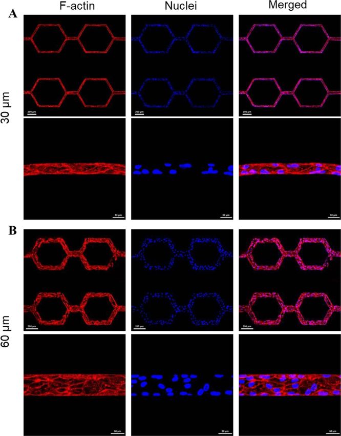
Biofabrication 13 (2021) 035006                                                                         F Zheng et al

excluded from these light-based additive manufacture       constructs with a spatial resolution significantly
approaches.                                                higher than extrusion based bioprinting. Aqueous
    Electrohydrodynamic (EHD) inkjet printing, is a        solution inks of Pluronic F127 (PF-127) were prin-
distinct material jetting technique that is related to     ted to provide sacrificial templates to form artificial
conventional drop-on-demand inkjet printing but            microvascular networks with a minimum channel
produces droplets considerably smaller in volume           diameter of 30 µm or 60 µm, embedded within
[26, 27]. Differing from conventional drop-on-             a gelatin methacryloyl (GelMA) hydrogel. Human
demand inkjet printing, EHD inkjet printing uses           dermal fibroblasts (HDFs) and human umbilical
electric fields, rather than thermal or acoustic energy,   vein endothelial cells (HUVECs) were seeded into
to create the fluid flows necessary for delivering inks    the engineered constructs to generate the structural
to a substrate [28]. By applying an electric potential     characteristics of a proto-tissue within an extracel-
difference between the printhead nozzle and the sub-       lular matrix (ECM). These cells formed supportive
strate, the ink fluid is charged, and the combination      ECM material and a functional endothelial layer after
of electrostatic and capillary forces leads to the form-   time in culture, exhibiting basic elements of a bioen-
ation of a characteristic conical shape, the Taylor cone   gineered artificial tissue with capillary scale vascu-
[29]. With the use of a pulsed potential, individual       lature. This approach provides a potential platform
drops can be ejected driven by the electric force. This    for creating artificial microvasculature at the capillary
drop formation mechanism allows EHD inkjet print-          scale in 3D.
ing to achieve droplet volumes in the 1 aL–fL range
(10−21 –10−18 m3 ) and a consequent line resolution        2. Materials and methods
from about 100 nm to a few microns (dependant on
ink surface contact angle [30]) after printing on sub-     2.1. Materials synthesis
strates. This improves the potential feature resolution    The synthesis of GelMA was achieved following a
compared to that of extrusion-based or conventional        sequential pH adjustment method, reported previ-
inkjet 3D printing by about three orders of mag-           ously [48]. Briefly, 20 g of type A gelatin (175 bloom)
nitude. This high-resolution printing capability has       derived from porcine skin tissue (Sigma-Aldrich,
enabled EHD inkjet printing to be used for a range         Gillingham, UK) was dissolved in 200 ml 0.1 M
of nano-/micro-fabrication applications, including:        carbonate-bicarbonate buffer (3.18 g Na2 CO3 and
DNA microarray printing [31], thin film transistor         5.86 g NaHCO3 in 1 l distilled water), 5 M NaOH
fabrication [32] and organic light emitting diode          or 6 M HCl was added as appropriate to achieve
devices [33]. The process is highly compatible with        pH = 9.0. Methacrylic anhydride (Sigma-Aldrich)
the deposition of hydrogels, thus EHD inkjet printing      was sequentially added (0.167 ml at each step) to the
has the potential to enable the fabrication of artifi-     gelatin solution every 30 min at 50 ◦ C. The solu-
cial microvasculature replicas at the native physical      tion pH value was monitored and readjusted to 9.0
scale. Note that although EHD printing has been            before each addition. The reaction was continued for
used to produce features with dimensions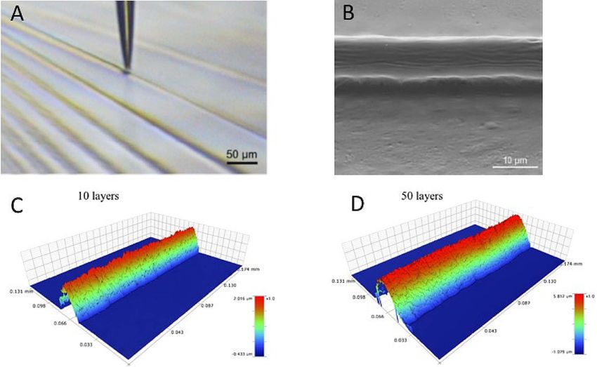
Biofabrication 13 (2021) 035006                                                                         F Zheng et al

dimethyl phenylphosphonite (1.5 g) and reacted at          [39] with minor modifications. Briefly, dopamine
room temperature under argon for 18 h. Four-fold           hydrochloride (Sigma-Aldrich) at 2 mg ml−1
excess of lithium bromide (Sigma-Aldrich) in 50 ml         (10.6 mM) was dissolved in sodium acetate (Sigma-
of 2-butanone (Sigma-Aldrich) was added to the             Aldrich) buffer at 50 mM, pH = 5.0. Next, sodium
reaction mixture and heated to 50 ◦ C for 10 min.          periodate (Sigma-Aldrich) was added as the oxidant
The mixture was cooled to ambient temperature,             to the solution at 4.5 mg ml−1 (21.2 mM) and quickly
allowed to rest for 4 h, and then filtered. The filtrate   vortex mixed until fully dissolved. The PDMS squares
was washed and filtered three times with 2-butanone        were then immediately immersed in the solution and
to remove unreacted lithium bromide, and excess            incubated at 40 ◦ C for 2 h. After the coating pro-
solvent was dried by vacuum. The final white powder        cess, the squares were rinsed with deionized water,
product was recovered in near quantitative yields and      air-dried and stored in dark conditions until further
analysed by proton nuclear magnetic resonance (1 H),       use.
matching literature data [37].
                                                           2.3. Construct fabrication
2.2. Ink, polymer solution and substrate                   Bioprinting was carried out using a commercial EHD
preparation                                                inkjet printing system (SLTS0505-KBD, SIJ Techno-
An aqueous solution of 10 wt% Pluronic F127                logy, Tsukuba, Japan). This was equipped with a
(PF-127, Sigma-Aldrich) in deionized water was used        glass capillary nozzle (tip diameter 2–2.5 µm), which
as the fugitive ink. The powder was homogenized in         was filled with 20 µl of the PF-127 ink using a
an ice bath with a magnetic stirrer, until fully dis-      micropipette. The ink was deposited onto a PDA-
solved. The ink was filtered using a 0.22 µm syringe       coated PDMS square substrate by applying pulsed
filter (Thermo Fisher Scientific, Waltham, MA, USA)        voltage >300 V. For monolayer printing, the nozzle
and subsequently stored at 4 ◦ C until further use.        tip ran at a working distance of ~3 µm from the sub-
     This study used GelMA as a pure hydrogel for          strate, while for multilayer printing, the nozzle tip was
structural fabrication and as a matrix for cell encap-     raised by 1 µm every three layers.
sulation. To prepare a pure GelMA solution, GelMA              Either pure GelMA solution or the GelMA cell
solid foam was dissolved in warm phosphate buffered        suspension was warmed to 37 ◦ C and cast onto
saline (PBS, Thermo Fisher Scientific) at 15 wt%,          the Pluronic patterned PDA-coated PDMS substrates,
with the LAP initiator added at 0.05 wt%. The mix-         which were contained in a 20 × 20 mm acrylic plastic
ture was vortex mixed and incubated at 37 ◦ C until        square box. The casting thickness was controlled at
fully dissolved. The solution was filtered by a 0.22 µm    ~500 µm. Following this, the GelMA hydrogel was
syringe filter and subsequently stored in dark condi-      crosslinked by illuminating with a UV light source
tions at 4 ◦ C until further use.                          (365 nm, 5 mW cm−2 ) for 30 s. After crosslinking, the
     For cell encapsulation studies, normal human          entire construct was flipped over and two stainless-
neonatal dermal fibroblasts (HDFs, PromoCell,              steel blunt nozzles with diameter 1 mm were inser-
Heidelberg, Germany) and green fluorescent pro-            ted through the PDMS substrate at two positions
tein expressing HDFs (GFP-HDFs, Angio Proteo-              of inlet and outlet. Nozzles were connected with an
mie, Boston, MA, USA) were used. Cells were first          external tubing (0.86 mm LDPE tubing, Portex, Smith
removed from culture flasks via the standard trypsin-      Medical, UK). Finally, the constructs were cooled to
ization procedure, then the cells were dispersed in a      4 ◦ C to liquify the embedded PF-127 features which
solution of GelMA and Dulbecco’s Modified Eagle            were extracted by applying a modest vacuum through
Medium (DMEM), with 15 wt% GelMA, 0.05 wt%                 the external tubing. The exposed hollow microchan-
LAP, at a concentration of 2 × 10⁶ cells ml−1 and          nels were rinsed with PBS buffer for three times,
gently pipetted up and down to mix evenly. A new           prior to further work of cell seeding and maintenance
batch of GelMA cell suspension was freshly prepared        in culture. Control specimens were prepared using
just prior to use.                                         identical substrates, without the printed Pluronic pat-
     To prepare polydimethylsiloxane (PDMS) sub-           tern, using the same volume of cell suspension and
strates with flat surfaces, degassed PDMS (Sylgard         hence cast thickness.
184, Dow Corning, Midland, MA, USA) liquid
mixture (10:1, oligomer:hardener) was poured               2.4. Cell seeding and culture
onto a silicon wafer (diameter 76.2 mm, Agar Sci-          Both normal human neonatal dermal fibroblasts
entific, Stansted, UK), contained in a Petri dish          (HDFs, PromoCell, Heidelberg, Germany) and
(100 × 15 mm). Thickness was set at 2 mm                   GFP-HDFs (Angio Proteomie, Boston, MA, USA)
and the mixture cured at 70 ◦ C for 2 h. The               were maintained in DMEM containing high gluc-
PDMS was then peeled from the silicon wafer and            ose and sodium pyruvate (DMEM, GlutaMAXTM,
trimmed into 20 × 20 mm squares. To improve                Gibco—Thermo Fisher Scientific) supplemented
cell adhesion, the surface of PDMS squares was             with 10% fetal bovine serum (FBS, Gibco) and 1%
coated by polydopamine (PDA). The coating treat-           penicillin/streptomycin (Thermo Fisher Scientific).
ment followed a protocol described previously              Both primary HUVECs (PromoCell, Germany)

                                              3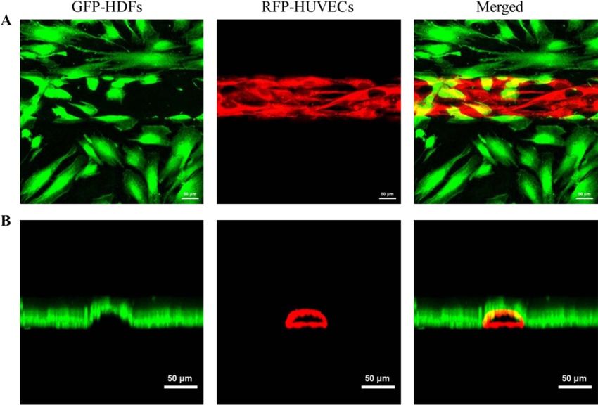
Biofabrication 13 (2021) 035006                                                                        F Zheng et al

and red fluorescent protein expressing HUVECs              with 1:2500 DAPI (Sigma-Aldrich) in PBS and 1:20
(RFP-HUVECs, Angio Proteomie, USA) were main-              phalloidin (Invitrogen) in PBS for 4 h. The fluores-
tained in EGM-2 medium (PromoCell, Germany)                cence images were captured using a TCS SP5 confocal
containing 1% penicillin/streptomycin (Thermo              microscope (Leica) with water-immersion objectives
Fisher Scientific). All the cell cultures were passaged    ranging from 10× to 40× using spectral lasers at 405,
following the respective vendor’s instructions and         488, 561, and 633 nm wavelengths. Z-stack images
incubated at 37 ◦ C, 5% CO2 . No cells were used bey-      were processed by the Leica provided software.
ond the ninth passage.                                         Fluorescein isothiocyanate–dextran (FITC-
    Prior to HUVEC seeding, the internal surfaces          dextran) dye, using 70 kDa dextran, was used to
of the microchannels were coated with fibronectin          visualize both bare and cell containing constructs.
to improve cell adhesion. Fibronectin solution at          For bare constructs, 25 µg ml−1 of FITC-dextran
0.01 mg ml−1 (Sigma-Aldrich) was injected into the         solution (FITC-dextran, Sigma-Aldrich) was directly
microchannels and incubated at 37 ◦ C for 30 min.          perfused into the microchannels. For cell containing
Then, the microvascular networks were flushed with         constructs, cell culture medium was first removed
fresh EGM-2 medium. 20 µl of HUVECs in sus-                and washed in PBS buffer three times, 25 µg ml−1 of
pension at the concentration of 1 × 10⁷ cells ml−1         Far-red-dextran (Alexa Fluor 647, Invitrogen) solu-
was injected to fill the network. Prior to the injec-      tion was then injected at a flow rate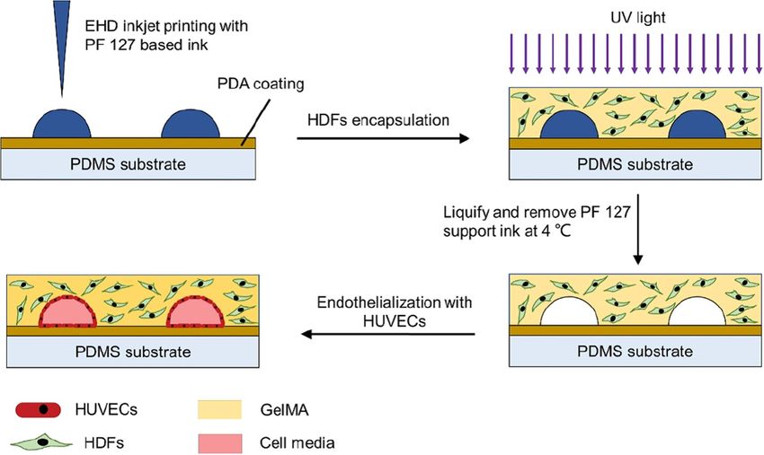
Biofabrication 13 (2021) 035006                                                                                            F Zheng et al

   Figure 1. Schematic of the manufacturing process using a sacrificial Pluronic F127 solution to form the microvasculature followed
   by casting a cell-containing GelMA suspension and photopolymerisation.

   Figure 2. (A) Image of the EHD inkjet printer in operation showing position of printer nozzle relative to the substrate. (B) SEM
   image of a printed Pluronic line formed by 20 repeated overprinting operations. Reconstructions of the printed ridges from
   optical profilometry data after: (C) 10, and (D) 50 layers overprinting.

was necessary to print 100 layers at a drop spacing                  of 30 µm and 60 µm, respectively. The PF-127 gel
of 3 µm. By adjusting the number of printed layers                   served as a temporary support to allow the patterning
and drop spacing, vascular channels with diamet-                     of internal features during the casting process,
ers in the range 20–60 µm were printed. For further                  and was removed by liquifying at low temperature
study with cell containing hydrogels two size scales                 (4 ◦ C) after the GelMA was photo-crosslinked and
were printed with minimum channel diameters                          gelled.

                                                       5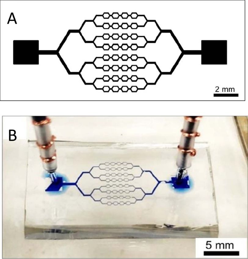
Biofabrication 13 (2021) 035006                                                                                       F Zheng et al

   Figure 3. (A) Schematic of an example microvascular network design showing large square injection and extraction manifolds at
   either end of a branching network. (B) Printed network in GelMA showing injection and extraction through the PDMA substrate
   layer.

     A typical microvascular network pattern is shown              channels, and their smallest branches connect each
in figure 3(A). It was designed to mimic the hierarch-             other to form a hexagonal network; here, the smallest
ical, bifurcating motifs found in biological systems,              channels were fabricated with the diameters of 30 µm
in which large channels bifurcate to form smaller                  and 60 µm, respectively. The images of the Z-stack 3D
channels that maximize efficient blood flow, nutri-                projections show a dome-like cross-section. Unlike
ent transport, and waste removal while minimizing                  soft lithography, which creates rectangular channels
the metabolic cost [9]. The central area of the pat-               with right angles, these half cylindrical channels with
tern was designed as a hexagonal network to mimic                  rounded corners fabricated by high resolution inkjet
the arteriole-venule connections at the capillary scale.           printing provides a more uniform tubular geometry,
Figure 3(B) displays an optical image of a microvas-               thereby offering a more suitable environment for fur-
cular tissue construct printed from the design in                  ther endothelial cell seeding.
figure 3(A). The engineered construct is fabricated on
a PDMS substrate, which serves as a waterproof and                 3.2. 3D culture of HDFs in microvascular tissue
self-sealing base. The PDMS substrate allows stain-                constructs
less steel needles to be inserted securely through at              To evaluate the ability of the microvascular net-
the inlet and outlet of the vascular mimic, to provide             works to support cells in the GelMA hydrogel matrix,
connection with external tubing. This eliminates the               HDFs were mixed with the GelMA precursor solu-
needles being inserted directly into the main body of              tion prior to photo-crosslinking. After casting and
the relatively fragile GelMA hydrogel. The PDMS sur-               cross-liking, the cell-containing microvascular con-
face is hydrophobic, which limits the affinity of mam-             structs were perfused with the DMEM cell culture
malian cells to effectively adhere [40, 41]. Thus, a PDA           medium, cells were maintained through perfusion at
coating was deposited on the PDMS, after which the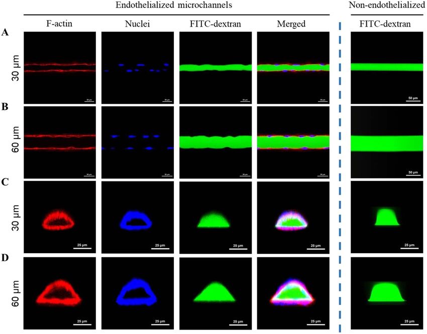
Biofabrication 13 (2021) 035006                                                                                           F Zheng et al

   Figure 4. Fluorescent images of FITC-dextran solution perfused through microchannels with smallest channel diameter of (A)
   30 µm and (B) 60 µm. Z-stack 3D projection images represent the lumen profile.

   Figure 5. Images of HDFs embedded in microvascular tissue constructs maintained by the perfused medium. Phalloidin was used
   to stain F-actin (green) and DAPI was used to stain the nuclei (blue). (A) Construct containing 60 µm diameter channels after 5 d
   (red dash lines highlight the vascular channel edge). (B) Construct containing 60 µm diameter channels after 21 d. (C) Construct
   containing 30 µm diameter channels after 21 d.

HDFs were encapsulated in GelMA hydrogel and                         cells colonized the entire hydrogel matrix, form-
displayed a rounded shape, scattered evenly within                   ing a densely populated structure. Identical results
the hydrogel matrix. After 5 d in culture, HDFs                      were observed with the GelMA constructs contain-
appeared spindle-shaped with filopodia-like protru-                  ing the smaller 30 µm diameter vascular channels
sions (figure 5(A)). These features became more obvi-                (figure 6(C)). HDFs extended along the surface of
ous after 21 d in culture and as shown in figure 5(B),               the microchannels. Preferential spreading around the

                                                      7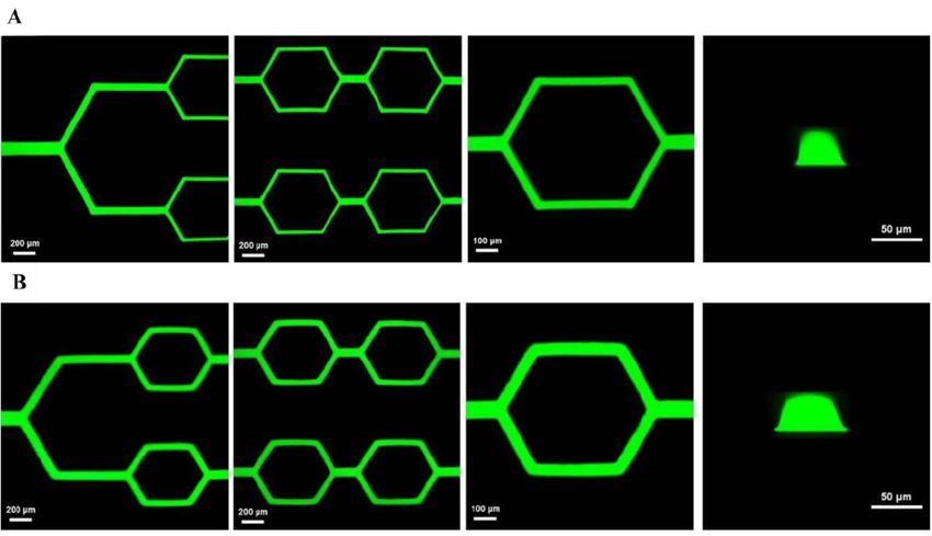
Biofabrication 13 (2021) 035006                                                                                          F Zheng et al

   Figure 6. Cell viability assay of HDFs embedded in the engineered 60 µm channel diameter microvascular patterned tissue
   constructs cultured over 21 d. (A) Fluorescence microscopy images showing live (green) and dead (red) cells, confirming high
   level of cell viability. (B) Cell viability in vascular GelMA constructs compared with control unvascularised GelMA.

   Figure 7. Fluorescent images of RFP-HUVECs seeded into 60 µm diameter microchannels showing uniform dispersion of
   HUVECs after seeding.

microchannels is likely related to the cells following              embedded in the vascular constructs exhibited high
contact guidance. The proximity of nutrient supply                  viability after 21 d in culture and formed dense cellu-
may also have promoted cells to migrate into the                    lar structures (figure 6(A)). There was a notable dif-
microchannel regions. Meanwhile, the actin microfil-                ference in the viability between the tissue constructs
aments of HDFs were found to wrap around the chan-                  with and without microvasculature (figure 6(B)).
nel walls forming ‘bridges’ across the microchannels.               Cells in the GelMA matrix without vascular channels
This phenomenon is likely because the microchan-                    died quickly and showed a clear reduction in viability
nel walls act as physical obstacle for cells to grow                with increasing time in culture, eventually only 13%
in the perpendicular direction, which is consist-                   of live cells remained after 21 d. Cells embedded in the
ent with other reports on topography-induced cell                   microvascular tissue constructs showed a high viabil-
alignment [42].                                                     ity (>90%) over 21 d culture. An analysis of variation
    Live/dead viability assays were performed over                  (one-way ANOVA) was performed across the time
21 d in 3D culture comparing the behaviour of                       points of the assay to test whether there was any vari-
the HDFs embedded in GelMA with 60 µm chan-                         ation in viability. The ANOVA returned p = 0.961,
nels and those cultured in an unvascularised GelMA                  this is considerably greater than the threshold for
structure of identical external dimensions. The HDFs                significance (p < 0.05) hence there was no reason

                                                      8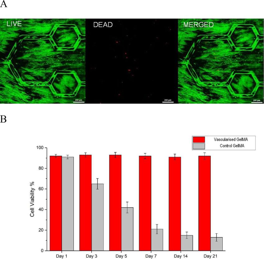
Biofabrication 13 (2021) 035006                                                                                         F Zheng et al

   Figure 8. Endothelialization of microvascular constructs. HUVECs were perfused into the microchannels with smallest feature
   size (A) 30 µm and (B) 60 µm and cultured for 3 d. Phalloidin was used to stain F-actin (red) and DAPI was used to stain the
   nuclei (blue).

to reject the null hypothesis. Although no live/dead                3.3. Endothelialization of microvascular tissue
assay was carried out with the cells in the GelMA with              constructs
30 µm diameter vasculature, comparison of the cell                  An endothelialization process was performed
density and morphology between cells grown in both                  by injecting HUVECs into the microchannels.
vascularised sample (figures 5(B) and (C)) found no                 This is illustrated in figure 7 through the use of
discernible difference. The fact that the presence of an            RFP-HUVECs to visualize the injection process
artificial perfused vascular network permits the main-              allowing imaging of the dynamic perfusion of cells.
tenance of cells in 3D culture supports the hypothesis              The seeded HUVECs were maintained at a perfused
that the presence of such a network is a necessary                  flow rate
Biofabrication 13 (2021) 035006                                                                                        F Zheng et al

   Figure 9. FITC-dextran flow perfusion in the endothelialized and non-endothelialized microvascular networks with channel size
   of (A), (C) 30 µm and (B), (D) 60 µm. (A) and (B) Top view presents different flow line profiles between endothelialized and
   non-endothelialized microchannels. (C) and (D) Cross-section view presents dome-like lumens formed by endothelial cells.
   Phalloidin was used to stain F-actin (red) and DAPI was used to stain the nuclei (blue).

phalloidin (Alexa Fluor 594) and DAPI for fluor-                   of the endothelium, thereby forming the irregular
escence imaging. As shown in figure 8, HUVECs                      line profile. Meanwhile, from the cross-sectional view
formed a confluent endothelial layer that covered the              of the microchannels, lumens were clearly visualized
entire surface of the microchannel network. HUVECs                 by F-actin, nucleus and the FITC-dextran solution
exhibited a cobble-stone pattern in keeping with a cel-            showing an arched lumen shape (figures 9(C) and
lular syncytium. Typically, HUVECs were observed                   (D)). Notably, unlike lithographic methods that cre-
with a venule-like morphology at the smallest branch-              ate rectangular channels with right angles, these half
ing channels of 30 µm and 60 µm in each construct                  cylindrical channels with rounded corners fabricated
design, respectively, which was likely induced by the              by multilayer EHD inkjet printing provides a more
low flow shear stress [43].                                        uniform tubular geometry, thereby offering a more
     In addition, to demonstrate the barrier func-                 suitable environment for the seeding of ECs [44].
tion of the confluent endothelial layer, we perfused
FITC-dextran solution through the endothelialized                  3.4. 3D co-culture of GFP-HDFs and RFP-HUVECs
microchannels to aid the visualization of flow. The                in microvascular tissue constructs
plan view of the constructs, as shown in figures 9(A)              To mimic the multiple cell types, present in nat-
and (B), demonstrated the fluorescent dextran flow                 ive vascularised tissue, we carried out co-culture
in the endothelialized microchannels, displayed an                 of GFP-HDFs and RFP-HVUECs in the engineered
irregular line profile created by the presence of the              microvascular tissue constructs. GFP-HDFs were
ECs lining the channel. This is in contrast to the                 encapsulated in the GelMA hydrogel patterned with
non-endothelialized bare GelMA constructs, where                   microvascular networks, followed by the endotheli-
the fluorescent dextran flow shows a well-defined                  alization with RFP-HUVECs. The cell seeded struc-
regular profile. It is believed that HUVECs formed                 tures were maintained by perfusing 1:1 ratio of
an endothelial layer attached to the inner wall of the             endothelial growth medium (EGM-2 medium) and
microchannels, which acts as a barrier between the                 HDF growth medium (DMEM plus 10% (vol/vol)
flow and the hydrogel matrix. The presence of nuc-                 FBS) in the microvascular networks. After 7 d cul-
lei in the cells leads to the non-uniform thickness                ture the GFP-HDFs spread into and colonized the

                                                    10
Biofabrication 13 (2021) 035006 F Zheng et al
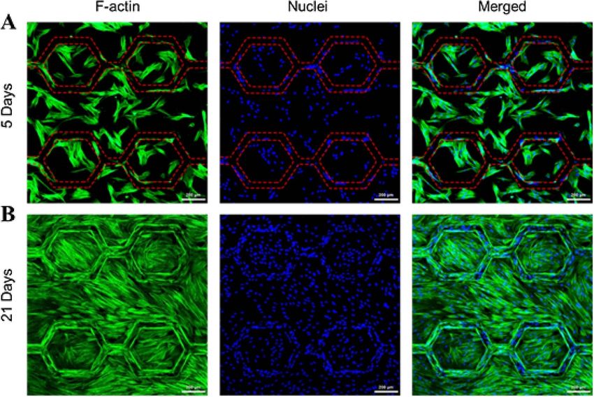
Figure 10. 3D co-culture of GFP-HDFs and RFP-HUVECs in 60 µm diameter microvascular tissue constructs for 7 d. (A)
GFP-HDFs formed supportive proto-tissue and RFP-HUVECs formed confluent endothelial layer (top view). (B) Cross-section
view presents a lumen of the endothelialized microchannels supported by the encapsulated GFP-HDFs with a typical cellular
density.
surrounding hydrogel matrix to form a dense proto- We consider whether EHD inkjet printing can
tissue (figure 10). The encapsulated GFP-HDFs pro- further push the limits of feature resolution for
duced reticular actin fibres wrapping around the biofabrication. It is clear from this work that we are
microchannels acting as a support structure. Mean- capable of printing tissue mimicking hydrogel struc-
while, HUVECs formed a confluent endothelium tures with a vasculature diameter of 30 µm that can
layer along the direction of microchannels. On cross- be successfully endothelialized and subsequently per-
section view, GFP-HDFs showed a typical spread- fused to maintain cells in 3D culture. In principle
ing confluent spindle cell morphology, which is likely the feature resolution can be pushed the required
due to their preference for surface adherence. RFP- factor of five smaller to achieve printed structures
HUVECs formed a monolayer of ECs along the with dimensions comparable to physiological capil-
lumens of microchannels. lary beds, although it is not clear whether channels
Finally, we developed a complete microvascu- of this scale could be endothelialized successfully by
lar tissue mimic by perfusing fluorescent dextran cell suspension perfusion without blockage. A fun-
solution into a GFP-HDFs/RFP-HUVECs co-culture damental issue with reducing the scale of feature
construct. To avoid colour overlap with fluorescent resolution is that the to maintain deposition rate,
cells, dextran was chosen with wavelength at 647 nm the drop generation frequency must scale with the
(far-red) and marked as blue pseudocolour in the inverse of drop volume and thus build times may
image post adjustments. Fluorescent dextran solu- become excessive. Another limitation to EHD depos-
tion represents blood flow perfused through the ition is the sensitivity of the process to the local elec-
microvascular networks, in which GFP-HDFs and tric field, and hence the substrate electrical proper-
RFP-HUVECs formed supportive prototissue and ties and the nozzle stand-off distance. This may limit
endothelium, respectively (figure 11). This engin- the accuracy of deposition when there is significant
eered 3D tissue construct simulates the basic com- heterogeneity in material composition during addit-
ponents of a perfusable microvasculature, includ- ive layer printing or non-planarity in the substrate
ing supportive ECM, viable tissue cells, a functional surface.
barrier endothelial layer, and blood flow; each of Finally, this is a preliminary platform that will
them was represented by GelMA hydrogel, GFP- be used to explore vascular development and bio-
HDFs, RFP-HUVECs and fluorescent dextran solu- logy. It is noted that vascular sprouting and neoan-
tion respectively. giogenesis beyond the construct channels has not
11Biofabrication 13 (2021) 035006 F Zheng et al
Figure 11. Perfusion of fluorescent dextran solution into a GFP-HDFs/RFP-HUVECs co-culture construct. Far-red dextran flow is
marked as blue pseudocolour after image processing.
been seen at 21 d. Future investigations aim to pro- the native microvasculature. Future utility of this
long the duration of study and add additional bio- approach can develop precise microvascular anatom-
logical triggers to try and develop the tissues further ies, and incorporate a range of different cell types to
by means of additional growth factor signalling [45], create bespoke vascularized tissues for drug testing or
mechanical forces [46] and other cells that facilitate even tissue replacement. The current platform opens
vascular development [47]. up a number of new avenues for fabricating and
investigating engineered functional tissues.
4. Conclusions
Acknowlegements
To conclude, we have presented a manufacturing
method based on high resolution EHD inkjet print-
This research was funded by the Engineering
ing to fabricate hydrogel-based microvascular tissue
and Physical Sciences Research Council (EPSRC),
constructs. The method integrates the printing/cast-
through grant EP/L012022/1, and by the Royal
ing process, offering superior spatial resolution, flex-
College of Surgeons of Edinburgh, through grant
ibility and hydrogel compatibility over conventional
SPPG/18/120. This work was also supported by
bioprinting approaches. Microvascular structures can
the Henry Royce Institute for Advanced Materi-
be fabricated with feature size down to 30 µm
als, funded through EPSRC grants EP/R00661X/1,
to mimic capillary vessels in the native arteriole-
EP/S019367/1, EP/P025021/1 and EP/P025498/1.
venule connections. Cells seeded in the microvascular
constructs exhibited their typical morphologies and
high cell viability after up to 21 d culture for both ORCID iDs
fibroblasts and ECs when compared to constructs
without microvascular channels. Heterogeneous tis- Brian Derby https://orcid.org/0000-0001-5753-
sue constructs with multiple cell types that are cap- 0166
able of long-term maintenance have been fabricated Jason Wong https://orcid.org/0000-0003-2592-
to replicate the basic composition and functions of 3226
12Biofabrication 13 (2021) 035006 F Zheng et al
References [24] Zhu W et al 2017 Direct 3D bioprinting of prevascularized
tissue constructs with complex microarchitecture
[1] Atala A, Bauer S B, Soker S, Yoo J J and Retik A B 2006 Biomaterials 124 106–15
Tissue-engineered autologous bladders for patients needing [25] Grigoryan B et al 2019 Multivascular networks and
cystoplasty Lancet 367 1241–6 functional intravascular topologies within biocompatible
[2] Macchiarini P et al 2008 Clinical transplantation of a hydrogels Science 364 458–64
tissue-engineered airway Lancet 372 2023–30 [26] Onses M S, Sutanto E, Ferreira P M, Alleyne A G and Rogers
[3] Kinstlinger I S and Miller J S 2016 3D-printed fluidic J A 2015 Mechanisms, capabilities, and applications of
networks as vasculature for engineered tissue Lab. Chip. high-resolution electrohydrodynamic jet printing Small
16 2025–43 11 4237–66
[4] Hasan A, Paul A, Vrana N E, Zhao X, Memic A, Hwang Y S, [27] Choi H K, Park J-U, Park O O, Ferreira P M, Georgiadis J G
Dokmeci M R and Khademhosseini A 2014 Microfluidic and Rogers J A 2008 Scaling laws for jet pulsations associated
techniques for development of 3D vascularized tissue with high-resolution electrohydrodynamic printing Appl.
Biomaterials 35 7308–25 Phys. Lett. 92 123109
[5] Sarker M D, Naghieh S, Sharma N K and Chen X 2018 3D [28] Derby B 2010 Inkjet printing of functional and structural
biofabrication of vascular networks for tissue regeneration: a materials: fluid property requirements, feature stability, and
report on recent advances J. Pharm. Anal. 8 277–96 resolution Annu. Rev. Mater. Res. 40 395–414
[6] Takei T, Sakai S and Yoshida M 2016 In vitro formation of [29] Yarin A L, Koombhongse S and Reneker D H 2001 Taylor
vascular-like networks using hydrogels J. Biosci. Bioeng. cone and jetting from liquid droplets in electrospinning of
122 519–27 nanofibers J. Appl. Phys. 90 4836–46
[7] Nomi M, Atala A, De Coppi P and Soker S 2002 Principals of [30] Stringer J and Derby B 2010 Formation and stability of lines
neovascularization for tissue engineering Mol. Aspects Med. produced by inkjet printing Langmuir 26 10365–72
23 463–83 [31] Park J U, Lee J H, Paik U, Lu Y and Rogers J A 2008
[8] Sarker M, Naghieh S, McInnes A D, Schreyer D J and Chen X Nanoscale patterns of oligonucleotides formed by
2018 Strategic design and fabrication of nerve guidance electrohydrodynamic jet printing with applications in
conduits for peripheral nerve regeneration Biotechnol. J. biosensing and nanomaterials assembly Nano Lett. 8 4210–6
13 1700635 [32] Kim S Y et al 2016 High-resolution electrohydrodynamic
[9] Fernandez C E, Achneck H E, Reichert W M and Truskey G inkjet printing of stretchable metal oxide semiconductor
A 2014 Biological and engineering design considerations for transistors with high performance Nanoscale 8 17113–21
vascular tissue engineered blood vessels (TEBVs) Curr. Opin. [33] Kim B H et al 2015 High-resolution patterns of quantum
Chem. Eng. 3 83–90 dots formed by electrohydrodynamic jet printing for
[10] Frerich B, Lindemann N, Kurtz-Hoffmann J and Oertel K light-emitting diodes Nano Lett. 15 969–73
2001 In vitro model of a vascular stroma for the engineering [34] Galliker P, Schneider J, Eghlidi H, Kress S, Sandoghdar V and
of vascularized tissues Int. J. Oral Maxillofac. Surg. 30 414–20 Poulikakos D 2012 Direct printing of nanostructures by
[11] Sarker M, Chen X B and Schreyer D J 2015 Experimental electrostatic autofocussing of ink nanodroplets Nat.
approaches to vascularisation within tissue engineering Commun. 3 890
constructs J. Biomater. Sci. Polym. Ed. 26 683–734 [35] Schneider J, Rohner P, Galliker P, Raja S N, Ying P, Tiwarib
[12] Udan R S, Culver J C and Dickinson M E 2013 M K and Poulikakos D 2015 Site-specific deposition of single
Understanding vascular development Wiley Interdiscip. Rev. gold nanoparticles by individual growth in
Dev. Biol. 2 327–46 electrohydrodynamically-printed attoliter droplet reactors
[13] Mironov V, Reis N and Derby B 2006 Bioprinting: a Nanoscale 7 9510
beginning Tissue Eng. 12 631–34 [36] Nie J, Gao Q, Xie C, Lv S, Qiu J, Liu Y, Guo M, Guo R, Fu J
[14] Derby B 2012 Printing and prototyping of tissues and and He Y 2019 Construction of multi-scale vascular chips
scaffolds Science 338 921–6 and modelling of the interaction between tumours and
[15] Murphy S V and Atala A 2014 3D bioprinting of tissues and blood vessels Mater. Horiz. 7 82–92
organs Nat. Biotechnol. 32 773–85 [37] Fairbanks B D, Schwartz M P, Bowman C N and Anseth K S
[16] Kolesky D B, Truby R L, Gladman A S, Busbee T A, Homan 2009 Photoinitiated polymerization of PEG-diacrylate with
K A and Lewis J A 2014 3D bioprinting of vascularized, lithium phenyl-2,4,6-trimethylbenzoylphosphinate:
heterogeneous cell-laden tissue constructs Adv. Mater. polymerization rate and cytocompatibility Biomaterials
26 3124–30 30 6702–7
[17] Bertassoni L E et al 2014 Hydrogel bioprinted microchannel [38] Majima T, Schnabel W and Weber W 1991
networks for vascularization of tissue engineering constructs Phenyl-2,4,6-trimethylbenzoylphosphinates as water-soluble
Lab. Chip. 14 2202–11 photoinitiators. Generation and reactivity of OṖ(C6H5)
[18] Kolesky D B, Homan K A, Skylar-Scott M A and Lewis J A (O−) radical anions Die Makromol. Chemie 192 2307–15
2016 Three-dimensional bioprinting of thick vascularized [39] Ponzio F, Barthès J, Bour J, Michel M, Bertani P, Hemmerlé J,
tissues Proc. Natl Acad. Sci. 113 3179–84 D’Ischia M and Ball V 2016 Oxidant control of
[19] Miller J S et al 2012 Rapid casting of patterned vascular polydopamine surface chemistry in acids: a
networks for perfusable engineered three-dimensional mechanism-based entry to superhydrophilic-
tissues Nat. Mater. 11 768–74 superoleophobic coatings Chem. Mater. 28 4697–705
[20] Chan V, Zorlutuna P, Jeong J H, Kong H and Bashir R 2010 [40] Lee J N, Jiang X, Ryan D and Whitesides G M 2004
Three-dimensional photopatterning of hydrogels using Compatibility of mammalian cells on surfaces of
stereolithography for long-term cell encapsulation Lab. Chip. poly(dimethylsiloxane) Langmuir 20 11684–91
10 2062–70 [41] Johnson L M, Gao L, Shields IV C, Smith M, Efimenko K,
[21] Arcaute K, Mann B K and Wicker R B 2006 Cushing K, Genzer J and López G P 2013 Elastomeric
Stereolithography of three-dimensional bioactive microparticles for acoustic mediated bioseparations J.
poly(ethylene glycol) constructs with encapsulated cells Ann. Nanobiotechnol. 11 22
Biomed. Eng. 34 1429–41 [42] Li H, Wong Y S, Wen F, Ng K W, Ng G K L, Venkatraman S S,
[22] Zhang A P, Qu X, Soman P, Hribar K C, Lee J W, Chen S and Boey F Y C and Tan L P 2013 Human mesenchymal stem-cell
He S 2012 Rapid fabrication of complex 3D extracellular behaviour on direct laser micropatterned electrospun
microenvironments by dynamic optical projection scaffolds with hierarchical structures Macromol. Biosci.
stereolithography Adv. Mater. 24 4266–70 13 299–310
[23] Tumbleston J R et al 2015 Continuous liquid interface [43] Chien S 2008 Effects of disturbed flow on endothelial cells
production of 3D objects Science 347 1349–52 Ann. Biomed. Eng. 36 554–62
13Biofabrication 13 (2021) 035006 F Zheng et al
[44] Green J V, Kniazeva T, Abedi M, Sokhey D S, Taslim M E and [47] Britto D D, Wyroba B, Chen W, Lockwood R A,
Murthy S K 2009 Effect of channel geometry on cell Tran K B, Shepherd P R, Hall C J, Crosier K E, Crosier P S
adhesion in microfluidic devices Lab. Chip. 9 677–85 and Astin J W 2018 Macrophages enhance Vegfa-driven
[45] Moccia F, Negri S, Shekha M, Faris P and Guerra G 2019 angiogenesis in an embryonic zebrafish tumour
Endothelial Ca2+ signaling, angiogenesis and xenograft model Dis. Model. Mech.
vasculogenesis: just what it takes to make a blood vessel Int. 11 dmm035998
J. Mol. Sci. 20 3962 [48] Lee B H, Shirahama H, Cho N J and Tan L P 2015 Efficient
[46] Gordon E, Schimmel L and Frye M 2020 The importance of and controllable synthesis of highly substituted gelatin
mechanical forces for in vitro endothelial cell biology Front. methacrylamide for mechanically stiff hydrogels RSC Adv.
Physiol. 11 684 5 106094–7
14You can also read