GETTING STARTED GUIDE AWS IOT CORE FOR LORAWAN - MULTITECH
←
→
Page content transcription
If your browser does not render page correctly, please read the page content below
Getting Started Guide
AWS IoT Core for LoRaWAN

                       Published 12/12/2020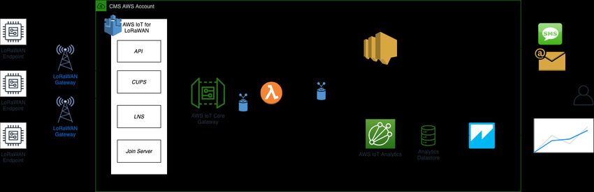
Table of Contents
1   Document Information ..................................................................................................................................... 3
2   Overview.......................................................................................................................................................... 3
3   Setup your AWS account and Permissions ......................................................................................................... 4
4   Set up the Gateway ........................................................................................................................................ 10
5   Add End Device(s)........................................................................................................................................... 12
6   Verifying Operation – a “Hello World” example ............................................................................................... 12
7   Debugging and Troubleshooting ..................................................................................................................... 19
1 Document Information
1.1 Naming Conventions
The term “downlink device” or “endpoint device” is used in this document to refer to a LoRaWAN device that
connects to a LoRaWAN “Gateway”. The “Gateway” in turn, connects to AWS IoT Core for LoRaWAN.

1.2 Revision History (Version, Date, Description of change)
1.1      12-Jan-2021

2 Overview
2.1 MultiTech Conduit® AP Access Point for LoRa® Technology:
The Conduit® AP conveniently provides deep in-building connectivity and improved performance for network
operators and enterprises connecting thousands of IoT assets by harnessing the power of the LoRaWAN® protocol.
Easy to deploy, the Conduit AP access point extends LoRa® connectivity in commercial buildings like hotels,
convention centers, offices and retail facilities providing coverage in difficult to reach areas cell tower or rooftop
deployments may not penetrate.
The Conduit AP offers a development environment for software developers and IT professionals alike. mPower™
edge intelligence features an easy-to-use graphical interface set-up and includes a built-in LoRa Network Server and
Packet Forwarder and basic station to connect locally clustered assets on a private LoRaWAN network directly to
your choice of IoT data platforms. The Conduit AP extends complex processing to the edge to reduce upstream
communication and operational costs. The Conduit AP provides Ethernet IP backhaul or optional 4G-LTE IP
backhaul.
mPower™ Edge Intelligence:
mPowerTM Edge Intelligence is a new embedded software offering, building on its popular application enablement
platform, to deliver programmability, network flexibility, enhanced security and manageability for scalable Industrial
Internet of Things (IIoT) solutions.

2.2 DataSheet
MTCAP-915-041 (US915) - https://www.multitech.com/documents/publications/data-sheets/86002211.pdf
MTCAP-868-041 (US868) - https://www.multitech.com/documents/publications/data-sheets/86002212.pdf

2.3 Standard Kit Contents
Your device ships with the following:

1 – MTCAP-915-041/ MTCAP-868-041
1 – 5 Volt, 2.5 Amp power supply
1 – RJ45 Ethernet cable
1 – LoRa antenna
1 – Dragino LHT65 Temperature & Humidity Sensor

2.4 User provided items:
A PC/Laptop with Ethernet capability.
2.5 3rd Party purchasable items
Look up more products at https://www.multitech.com/products/product-selector or Contact sales@multitech.com
for additional sensors.
2.6 Additional Hardware References
https://www.multitech.com/
https://www.multitech.com/products/product-selector
https://www.multitech.com/onboard
https://www.multitech.com/connect
https://www.multitech.com/brands/multiconnect-conduit-ap
3 Setup your AWS account and Permissions
If you don’t have an AWS account, refer to the instructions in the guide here. The relevant sections are Sign up for
an AWS account and Create a user and grant permissions.
3.1 Overview
The high-level steps to get started with AWS IoT Core for LoRaWAN are as follows:
1. Set up Roles and Policies in IAM
2. Add a Gateway (see section Add the Gateway to AWS IoT)
3. Add Device(s) (see section Add a LoRaWAN Device to AWS IoT)
a. Verify device and service profiles
b. Set up a Destination to which device traffic will be routed and processed by a rule.
These steps are detailed below. For additional details, refer to the AWS LoRaWAN developer guide.
3.2 Set up Roles and Policies in IAM
3.2.1 Add an IAM Role for CUPS server
Add an IAM role that will allow the Configuration and Update Server (CUPS) to handle the wireless gateway
credentials.
This procedure needs to be done only once, but must be performed before a LoRaWAN gateway tries to connect
with AWS IoT Core for LoRaWAN.
First, create the policy that will be used for the IAM role.
Go to the IAM console
Choose Policies from the navigation pane.
Choose Create Policy. Then choose the JSON tab to open the policy editor. Replace the existing template
with this trust policy document:
{
"Version": "2012-10-17",
"Statement": [
{
"Sid": "IoTWirelessGatewayCertManager",
"Effect": "Allow",
"Action": [
"iot:CreateKeysAndCertificate",
"iot:DescribeCertificate",
"iot:ListCertificates",
"iot:RegisterCertificate"
],
"Resource": "*"}
]
}
Choose Review Policy to open the Review page.
For Name, enter AWSIoTWirelessGatewayCertManager. Note that you must enter name as
AWSIoTWirelessGatewayCertManager and must not use a different name. This is for consistency with
future releases.
For Description, enter a description of your choice.
Choose Create policy. You will see a confirmation message showing the policy has been created.
Next, create the IAM role and assign the policy you just created.
Go to the IAM Roles page on the IAM console
Choose Create role.
On the Create Role page, choose Another AWS account.
For Account ID, enter your account id.
Choose Next: Permissions
In the search box next to Filter policies, enter AWSIoTWirelessGatewayCertManager.
Choose Next: Tags, and then choose Next: Review.
In Role name, enter IoTWirelessGatewayCertManagerRole, and then choose Create role.
o Note that you must enter name as IoTWirelessGatewayCertManagerRole and must not use a
different name. This is for consistency with future releases.
In the confirmation message, choose IoTWirelessGatewayCertManagerRole to edit the new role.
In the Summary, choose the Trust relationships tab, and then choose Edit trust relationship.
In the Policy Document, change the Principal property to represent the IoT Wireless service:
"Principal": {
"Service": "iotwireless.amazonaws.com"
},
After you change the Principal property, the complete policy document should look like this:
{
"Version": "2012-10-17",
"Statement": [
{
"Effect": "Allow",
"Principal": {
"Service": "iotwireless.amazonaws.com"
},
"Action": "sts:AssumeRole",
"Condition": {}
}
]
}
Choose Update Trust Policy to save your changes and exit.
At this point, you’ve created the IoTWirelessGatewayCertManagerRole and you won’t need to do this again.
3.2.2 Add IAM role for Destination to AWS IoT Core for LoRaWANPrepare your AWS account to work with AWS IoT Core for LoRaWAN. First, create an IAM role with permissions to
describe the IoT end point and to deliver messages to IoT cloud. Then, update the trust policy to grant AWS IoT Core
for LoRaWAN permission to assume this IAM role when delivering messages from devices to your account.
NOTE – The examples in this document are intended only for dev environments. All devices in your fleet must
have credentials with privileges that authorize only intended actions on specific resources. The specific
permission policies can vary for your use case. Identify the permission policies that best meet your business and
security requirements. For more information, refer to Example policies and Security Best practices.
Create the corresponding policy
Go to the IAM console
Choose Policies from the navigation pane.
Choose Create Policy. Then choose the JSON tab to open the policy editor. Replace the existing template
with this trust policy document:
{
"Version": "2012-10-17",
"Statement": [
{
"Effect": "Allow",
"Action":
[
"iot:DescribeEndpoint",
"iot:Publish"
],
"Resource": "*"
}
]
}
Choose Review Policy to open the Review page. For Name, enter a name of your choice. For Description,
enter a description of your choice.
Choose Create policy.
Create the corresponding role
In the IAM console, choose Roles from the navigation pane to open the Roles page.
Choose Create Role.
In Select type of trusted entity, choose Another AWS account.
In Account ID, enter your AWS account ID, and then choose Next: Permissions.
Choose Next: Permissions
Search for your IAM policy. Type in the policy name to find your policy. Select it.
Choose Next: Tags.
Choose Next: Review to open the Review page. For Role name, enter an appropriate name of your choice.
For Description, enter a description of your choice.
Choose Create role.
Update your policy's trust relationship.
In the IAM console, choose Roles from the navigation pane to open the Roles page
Enter the name of the role you created earlier in the search window, and click on the role name in the
search results
Choose the Trust relationships tab to navigate to the Trust relationships page.
Choose Edit trust relationship. The principal AWS role in your trust policy document defaults to root.
Replace the existing policy with this:
{"Version": "2012-10-17",
"Statement": [
{
"Sid": "",
"Effect": "Allow",
"Principal": {
"Service": "iotwireless.amazonaws.com"
},
"Action": "sts:AssumeRole",
"Condition": {}
}
]
}
Choose Update Trust Policy
3.3 Add the Gateway to AWS IoT
3.3.1 Preparation
To complete setting up your gateway, you need:
LoRaWAN region. For example, if the gateway is deployed in a US region, the gateway must support LoRaWAN
region US915.
Gateway LNS-protocols. Currently, the LoRa Basics Station protocol is supported.
Gateway ID (GatewayEUI) or serial number. This is used to establish the connection between the LNS and the
gateway. Consult the documentation for your gateway to locate this value.
Make sure your MultiTech gateway is on mPower™ version 5.3.0 or higher you can find the firmware download
here: http://www.multitech.net/developer/downloads/
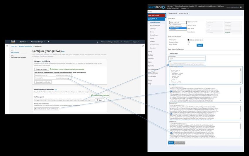
3.3.2 Add the LoRaWAN Gateway
To register the Gateway with AWS IoT Core for LoRaWAN, follow these steps:
Go to the AWS IoT Core console.
Select Wireless connectivity in the navigation panel on the left.
Choose Intro, and then choose Get started. This step is needed to pre-populate the default profiles.
Under Add LoRaWAN gateways and wireless devices, choose Add gateway.
In the Add gateway section, fill in the GatewayEUI and Frequency band (RF Region) fields.
Enter a descriptive name in the Name – optional field. We recommend that you use the GatewayEUI as the
name.
Choose Add gateway
On the Configure your Gateway page, find the section titled Gateway certificate.
Select Create certificate.
Once the Certificate created and associated with your gateway message is shown, select Download certificates to
download the certificate (xxxxx.cert.pem) and private key (xxxxxx.private.key).
(You will open these files in a notepad application and copy paste the contents into the gateway UI basic station
configuration)
In the section Provisioning credentials, choose Download server trust certificates to download the CUPS
(cups.trust) and LNS (lns.trust) server trust certificates.
Copy the CUPS and LNS endpoints and save them for use while configuring the gateway.
Choose Submit to add the gateway.
3.4 Add a LoRaWAN Device to AWS IoT
3.4.1 Preparation
Locate and note the following specifications about your endpoint device.
o LoRaWAN region. This must match the gateway LoRaWAN region. The following Frequency bands (RF
regions) are supported:
o EU868o US915
o EU433
o MAC Version. This must be one of the following:
o V1.0.2
o v1.0.3
o v1.1
o OTAA v1.0x and OTAA v1.1 are supported.
o ABP v1.0x and ABP v1.1 are supported.
Locate and note the following information from your device manufacturer:
For OTAA v1.0x devices: DevEUI, AppKey, AppEUI
For OTAA v1.1 devices: DevEUI, AppKey, NwkKey, JoinEUI
For ABP v1.0x devices: DevEUI, DevAddr, NwkSkey, AppSkey
For ABP v1.1 devices: DevEUI, DevAddr, NwkSEnckey, FNwkSIntKey, SNwkSIntKey, AppSKey
3.4.2 Verify Profiles
AWS IoT Core for LoRaWAN supports device profiles and service profiles. Device profiles contain the
communication and protocol parameter values the device needs to communicate with the network server. Service
profiles describe the communication parameters the device needs to communicate with the application server.
Some pre-defined profiles are available for device and service profiles. Before proceeding, verify that these profile
settings match the devices you will be setting up to work with AWS IoT Core for LoRaWAN.
Navigate to the AWS IoT Core console. In the navigation pane, choose Wireless connectivity.
In the navigation pane, choose Profiles
In the Device Profiles section, there are some pre-defined profiles listed.
Check each of the profiles to determine if one of them will work for you.
If not, select Add device profile and set up the parameters as needed. For US 915 as an example, the values
are:
o MacVersion 1.0.3
o RegParamsRevision RP002-1.0.1
o MaxEirp 10
o MaxDutyCycle 10
o RfRegion US915
o SupportsJoin true
Continue once you have a device profile that will work for you.
In the Service Profiles section, there are some pre-defined profiles listed. Check each of the profiles to
determine if one of them will work for you.
If not, select Add service profile and set up the parameters as needed. As an example, the default service
profile parameters are shown below. However, only the AddGwMetadata setting can be changed at this
time.
o UlRate 60
o UlBucketSize 4096
o DlRate 60
o DlBucketSize 4096
o AddGwMetadata true
o DevStatusReqFreq 24
o DrMax 15
o TargetPer 5
o MinGwDiversity 1
Proceed only if you have a device and service profile that will work for you.3.4.3 Set up a Destination for device traffic
Because most LoRaWAN devices don't send data to AWS IoT Core for LoRaWAN in a format that can be consumed
by AWS services, traffic must first be sent to a Destination. A Destination represents the AWS IoT rule that
processes a device's data for use by AWS services. This AWS IoT rule contains the SQL statement that selects the
device's data and the topic rule actions that send the result of the SQL statement to the services that will use it.
For more information on Destinations, refer to the AWS LoRaWAN developer guide.
A destination consists of a Rule and a Role. To set up the destination:
Navigate to the AWS IoT Core console. In the navigation pane, choose Wireless connectivity, and then
Destinations
Choose Add Destination
On the Add destination page, in the Permissions section select the IAM role you had created earlier, from
the drop-down.
Under Destination details enter ProcessLoRa as the Destination name, and an appropriate description under
Destination description – optional.
NOTE: The Destination name can be anything. For getting started and consistency, choose ProcessLoRa
for the first integration with AWS IoT Core for LoRaWAN.
For Rule name enter LoRaWANRouting. Ignore the section Rules configuration – Optional for now. The
Rule will be set up later in the “Hello World” sample application – see Create the IoT Rule for the
destination
Choose Add Destination. You will see a message “Destination added”, indicating the destination has been
successfully added.
3.4.4 Register the Device
Now register an endpoint device with AWS IoT Core for LoRaWAN as follows:
Go to the AWS IoT Core console.
Select Wireless connectivity in the navigation panel on the left.
Select Devices
Choose Add wireless device
On the Add device page, select the LoRaWAN specification version in the drop-down under Wireless device
specification.
Under LoRaWAN specification and wireless device configuration, enter the DevEUI and confirm it in the Confirm
DevEUI field.
Enter the remaining fields as per the OTAA/ABP choice you made above.
It is recommended that you enter the DevEUI for your device in the Wireless device name field.
In the Profiles section, under Wireless device profile, find a drop-down option that corresponds to your device
and region.
o NOTE: Compare your device details to ensure the device profile is correct. If there are no valid default
options, you will have to create a new profile (see the section Verify Profiles).
Choose Next
Choose the destination you created earlier (ProcessLoRa) from the drop-down under Choose destination.
Choose Add device
You will see a message saying “Wireless device added”, indicating that your device has been set up successfully.4 Set up the Gateway
4.1 Set up Gateway hardware
Connect the Ethernet cable from the gateway to the computer/laptop.
Screw in the LoRa antenna to the connector to the MTCAP.
Plug in the gateway to a power supply to power it up.
Gateway will go through the boot process
Gateway will be up and ready when the ‘status’ LED is flashing
LEDs
STATUS Blinks when operating system is fully loaded.
LORA Lights when LoRa software is active.
Ethernet Link Left LED on the Ethernet connector. Blinks when data is sent or received on the Ethernet link.
Steady light when there is a valid Ethernet connection.
Ethernet Speed Right LED on the Ethernet connector. Lit when the Ethernet is linked at 100 Mbps. If not lit,
the
Ethernet is linked at 10 Mbps.
Change Adapter settings to Connect to Gateway:
o On a Windows computer go to the control panel
o Select Network and Internet
o Select Network and sharing Center
o Select Change Adapter Settings
o Right Click Ethernet
o The Ethernet Dialog Box will open, select Internet Protocol Version 4(TCP/IPv4) and click the
Properties button
o Select Use the Following and fill out the following fields accordingly
IP Address: Enter an IP Address on the default subnet
Example: 192.168.2.XXX
Subnet Mask: 255.255.255.0 [Note:] leave the DNS address blank you do not need an IP
address for this configuration.
4.2 Set up Gateway Software
Open a web browser and enter the device’s default ip address http://192.168.2.1
A security window will open, click on the Advanced button to bypass, then click on “Proceed to
192.168.2.1”
This will open up commissioning mode, create username and strong password
Log into the gateway with new username to admin & strong password
This will take you to the First-Time Setup Wizard
Click Next, Click Next again to skip the Call Home Setup. Set the Date, Time and Time Zone
Exit the First-Time Setup Wizard
Configure the Gateway Ethernet as a WAN interface.
o Navigate to Setup -> Network Interfaces
o Click the edit Icon next to eth0
Set the following
Direction: WAN
Mode: Static
IP Address: Set your desired ip address on the same subnet as your routerEx. If router ip is 192.168.1.1 set ip address to 192.168.1.xxx
Mask: 255.255.255.0
Gateway: 192.168.1.151 Point to your router’s ip address
Primary DNS server: 8.8.8.8
Click Submit
Navigate to Administration -> Access Configuration
Make sure the following are checked.
o HTTP Redirect to HTTPS: all checked
o HTTPS via WAN
o SSH via LAN & via WAN
o ICMP Settings: All checked
Click Submit
Click Save and Apply, the gateway will reboot (Click “Ok” when prompted).
Check Internet Access on the Gateway:
o Remove your Ethernet port from computer and plug into your router
o Wait for the gateway to boot up
o On Windows, in the search window type “cmd” and select “Command Prompt”
o From the Command Line SSH into your gateway set ip address
o $ ssh admin@192.168.1.151
o Once logged into the gateway, type and enter “ping google.com” check in the gateway has
internet access. You should see bytes of data being sent.
o example:
Pinging www.google.com [172.217.8.164] with 32 bytes of data:
Reply from 172.217.8.164: bytes=32 time=25ms TTL=114
4.3 Additional Software References
There is additional support available for Multitech gateways at:
http://www.multitech.net/developer/
You can raise a support ticket at https://support.multitech.com/
4.4 Configure the Gateway device
LoRa and Basic Station Configuration:
o To setup basic station select "LoRaWAN" on the main UI then "Network Settings" (this should be
the default).
o Change the "Mode" combobox to "BASIC STATION". The fields on this page now correspond to
each of the files that Basic Station needs to initiate a connection (more information about this can
be found in the Semtech Basic Station documentation at https://doc.sm.tc/station/)
Credentials: set it to “CUPS”. (AWS uses CUPS authentication, not LNS. You can read
more about LNS and CUPS here https://doc.sm.tc/station/credentials.html#files-types)
URI: URI of the network server. The URI will be provided/generated when you create a
gateway on AWS. See Add the LoRaWAN Gateway for details on how to get the CUPS
endpoint.
Station config: This is the same as a Semtech UDP packet forwarder file. Use the
example file from the UI already populated for you.
Server Cert: This is the *.trust downloaded from AWS earlier. Copy and paste the
contents of the file into this field. Gateway Cert: This is the *.crt file downloaded from AWS earlier. Copy and paste the
contents of the file into this field.
Gateway Key: This is for the *.key file downloaded from AWS earlier. Copy and paste the
contents of the file into this field.
o After filling each of the fields click “Submit” at the bottom of the page, then "Save and Apply"
5 Add End Device(s)
Press and hold ACT button for 5 secs until the light flashes red.
For more info on device working refer to the LHT65 user manual
http://www.dragino.com/downloads/downloads/LHT65/UserManual/LHT65_Temperature_Humidity_Sensor_User
Manual_v1.3.pdf
6 Verifying Operation – a “Hello World” example
Once setup is completed, provisioned OTAA devices can join the network and start to send messages. Messages
from devices can then be received by AWS IoT Core for LoRaWAN and forwarded to the IoT Rules Engine.
Instructions for a sample Hello World application are given below, assuming that the device has joined and is
capable of sending uplink traffic. The architecture for this sample application is:6.1 Create lambda function for destination rule
Create the lambda function to process device messages processed by the destination rule.
Go to the AWS Lambda console (console.aws.amazon.com/lambda).
Click on Functions in the navigation pane
Click on Create function
Select Author from scratch. Under Basic information, enter the function name “sailboatdecoder” and
choose Runtime Node.js 12.x. from the drop-down under Runtime.
Click on Create function. Navigate to
https://github.com/MultiTechSystems/aws_lambda_example/blob/master/decode_dragino_lht65.js
and copy the code for the lambda function.
Under Function code, paste the copied code into the editor under the index.js tab.
Once the code has been pasted, choose “Deploy” to deploy the lambda code.
Click on the Permissions tab of the lambda function
Change the Lambda Role Policy permission
o Under Execution role, click on the hyperlink under Role name
o On the Permissions tab, find the policy name and click on it
o Choose Edit policy, and choose the JSON tab
o Append the following to the Statement section of the policy to allow publishing to AWS IoT. (Note the
leading comma below)
,
{
"Effect": "Allow",
"Action": [
"iot:Publish"
],
"Resource": [
"*"
]
}
o Choose Review Policy, then Save changes
Create a test event that will allow you to test the functionality of the lambda function.
o In the drop-down for Select a test event, choose Configure test events
o Enter a name for the test event under Event name
o Paste the following sample payload in the area under Event name:
{
"MessageId": "55d122ab-6355-2233-9874-ff47c5222108","WirelessDeviceId": "65d128ab-90dd-4668-9556-fe47c589610b",
"PayloadData": "zA0LYgHpAX//f/8=",
"WirelessMetadata":
{
"LoRaWAN":
{
"DevEui": "a84041000181bf255",
"FPort": 2,
"DataRate": 0,
"Frequency": 904500000,
"Gateways": [
{
"GatewayEui": "80029cfffeffff",
"Snr": 12.25,
"Rssi": -47
}
],
"Timestamp": "2020-12-14T08:23:56Z"
}
}
}
Choose Create to save the event
Navigate to the AWS IoT Core console, choose Test on the navigation pane, and select MQTT client.
Configure the MQTT client to subscribe to “#” (all topics)
Click on Test in the Lambda function page to generate the test event you just created
Verify the published data in the AWS IoT Core MQTT Test client. (Open another window. Goto AWS IoT
Console, select Test, under Subscription Topic, enter # and select to Subscribe to topic). It should look
similar to this:
6.2 Create the Destination rule
In this step, you create the IoT rule that forwards the device payload to your application. This rule is associated with
the destination created earlier in Set up a Destination for device traffic.
Navigate to the AWS IoT Core console.
In the navigation pane, choose Act. Then, choose Rules.
On the Rules page, choose Create.
On the Create a rule page, for Name, enter LoRaWANRouting. For Description, enter a description of your
choice. Note the name of your rule. The information will be needed when you provision devices to run on
AWS IoT Core for LoRaWAN.
Leave the default Rule query statement: ‘SELECT * FROM 'iot/topic' unchanged.
Under Set one or more actions choose Add action. On the Select an action page, choose Republish a message to an AWS IoT topic. Scroll down and choose
Configure action.
On the Configure action page, for Topic, enter project/sensor/decoded. The AWS IoT Rules Engine will
forward messages to this topic.
Under Choose or create a role to grant AWS IoT access to perform this action, choose Create Role.
For Name, enter a name of your choice.
Choose Create role to complete the role creation. You will see a “Policy Attached” tag next to the role
name, indicating that the Rules Engine has been given permission to execute the action.
Choose Add action.
Add one more action to invoke the Lambda function. Under Set one or more actions choose Add action.
Choose Send a message to a Lambda function
Choose Configure action
Select the sailboatdecoder lambda function created earlier and choose Add action
Then, choose Create rule.
A “Success” message will be displayed at the top of the panel, and the destination has a rule bound to it.
You can now check that the decoded data is received and republished by AWS by triggering a condition or event
on the device itself.
1. Go to the AWS IoT console. In the navigation pane, select Test, and choose MQTT client.
2. Subscribe to the wildcard topic ‘#” to receive messages from all topics
3. You should see traffic similar to that shown below.6.3 Configuring SNS
We will use the Amazon Simple Notification Service to send text messages (SMS) when certain conditions are met.
Go to the AWS SNS console.
Click on menu in the left corner to open the navigation pane.
Select Text Messaging (SMS) and choose Publish text message.
Under Message type, select Promotional.
Enter your phone number (phone number that will receive text alerts)
Enter “Test message” for the Message and choose Publish message.
If the phone number you entered is valid, you will receive a text message and your phone number will be
confirmed.
Create an SNS Topic as follows:
o In the navigation pane, choose Topics
o Select Create topic
o Under Details, select Standard
o Enter a name of your choice. Here we will use “text_topic”.
o Select Access Policy – optional
o Under Choose method, select Basic
o For Define who can send messages to this topic, select Everyone
o Choose Create topic
Create a subscription for this topic:
o In the page for the newly created text_topic, choose the Subscriptions tab
o Choose Create subscription
o Select Protocol as SMS from the drop-down
o Under Endpoint, enter the previously validated phone number to receive the SMS alertso Choose Create subscription. You should see a “Subscription to text_topic created successfully”
message.
6.3.1 Add a rule for SNS notification
Now add a new rule to send an SNS notification when certain conditions are met in a decoded message.
Navigate to the AWS IoT Core console.
In the navigation pane, choose Act. Then, choose Rules.
On the Rules page, choose Create
Enter the Name as text_alert, and provide an appropriate Description
Under Rule query statement, enter the following query:
SELECT DevEUI as device_id, "Temperature exceeded 80" as message,
Alert_Temp as temp, Humidity as humidity, Timestamp as time FROM
'+/project/sensor/decoded' where Alert_Temp > 80
Choose Add action
Choose Send a message as an SNS push notification
Choose Configure action
Under SNS target, select text_topic from the drop-down
Select RAW under Message format
Under Choose or create a role to grant AWS IoT access to perform this action, choose Create role.
Enter a name for the role and choose Add action
Choose Create rule. You should see a “Success” message, indicating that the rule has been created.
6.3.2 Test the complete flow from the sensor
Hold the sensor in your hand for a minute. If possible, place your hand to cover the sensor on top to
increase the reading due to body temperature.
Press and hold ACT button for 5 sec until the light flashes red.
Verify the SMS on your phone from the sensor.
6.4 IoT Analytics
We will use IoT Analytics to visually display data via graphs if there is a need in the future to do further analysis.
6.4.1 Create an IoT Analytics Rule
First create a rule
Navigate to the AWS IoT Core console.
In the navigation pane, choose Act. Then, choose Rules.
On the Rules page, choose Create
Enter the Name as Visualize, and provide an appropriate Description
Under Rule query statement, enter the following query:
SELECT * FROM '+/project/sensor/decoded'
Choose Add action
Select Send a message to IoT Analytics
Choose Configure Action
Choose Quick Create IoT Analytics Resources
Under Resource Prefix, enter an appropriate prefix for your resources, such as LoRa
Choose Quick Create
Once the Quick Create Finished message is displayed, choose Add action.
Choose Create rule. You should see a Success message, indicating that the rule has been created.6.4.2 Configure IoT Analytics
Set up IoT Analytics as follows:
Go to the AWS IoT Analytics console.
In the navigation panel, choose Data sets
Select the data set that was generated by the Quick Create in Create an IoT Analytics Rule
In the Details section, Edit the SQL query.
Replace the query with:
select Alert_Temp as temp, Humidity as humidity, DevEUI as device_id, Timestamp
as time from LoRa_datastore
Under Schedule, choose Add schedule
Under Frequency, choose Every 1 minute, and choose Save
6.4.3 Configure QuickSight
QuickSight lets you easily create and publish interactive BI dashboards that include Machine Learning-powered
insights.
Go to AWS Management console.
From the management console, enter “QuickSight” in the “Search for services, features..” search box.
Click on QuickSight in the search results
If you haven’t signed up for the service before, go ahead and sign up, as there is a free trial period.
Select the Standard Edition, and choose Continue
Enter a unique name in the field QuickSight account name
Fill in the Notification email address
Review the other checkbox options and change them as necessary. The AWS IoT Analytics option must be
selected.
Choose Finish. You will see a confirmation message.
Choose Go to Amazon QuickSight
Select Datasets.
Select New dataset
Select AWS IoT Analytics
Under Select an AWS IoT Analytics data set to import, choose the data set created in Create an IoT Analytics
Rule
Choose Create data source, and then choose Visualize
Select dataset created, then select Refresh or Schedule Refresh for periodic refresh of dataset.
6.5 Testing your “Hello World” Application
Using your device, create a condition to generate an event such as a high temperature condition. If the
temperature is above the configured threshold then you will receive a text alert on your phone. This alert will
include key parameters about the alert.
You can also visualize the data set as follows:
Go to the AWS IoT Analytics console
Choose Data sets
Select the dataset created earlier
Select Content. and ensure there are at least few uplink entries available in the data set. Go to the QuickSight console
Choose New analysis
Choose the dataset created in Create an IoT Analytics Rule
Select time on the X-axis, Value as temp (Average) and Color as device_id to see a chart of your dataset.
7 Debugging and Troubleshooting
On Windows, in the search window type “cmd” and select “Command Prompt”
From the Command Line SSH into your gateway ip address
$ ssh admin@192.168.1.151
Type “sudo –s” and enter the same password as the admin password to gain root privilege.
Type “/etc/init.d/lora-network-server stop” and hit return to stop the lora services running on the device.
Using an editor like vi edit the “log_level” from INFO to XDEBUG in the file /run/lora/1/ station.conf
o NOTE: Don’t forget to turn it back to INFO after you are finished debugging.
You are ready to run the basic station as an executable which will provide debug level logs for
troubleshooting. Type “./station” to run.
The output should look something like below:root@mtcap:/run/lora/1# ./station
A normal operation should look like below
2020-12-13 05:16:08.816 [SYS:INFO] Logging : stderr (maxsize=100000, rotate=3)
2020-12-13 05:16:08.817 [SYS:INFO] Station Ver : 2.0.5(mlinux/std) 2020-10-20 09:11:05
2020-12-13 05:16:08.817 [SYS:INFO] Package Ver : (null)
2020-12-13 05:16:08.817 [SYS:INFO] proto EUI : 80:0:1:5de8 (station.conf)
2020-12-13 05:16:08.817 [SYS:INFO] prefix EUI : ::0 (station.conf)
2020-12-13 05:16:08.817 [SYS:INFO] Station EUI : 80:0:1:5de8
2020-12-13 05:16:08.818 [SYS:INFO] Station home: ./ (builtin)
2020-12-13 05:16:08.818 [SYS:INFO] Station temp: /var/tmp/ (builtin)
2020-12-13 05:16:08.818 [SYS:WARN] Station in NO-CUPS mode
2020-12-13 05:16:09.020 [TCE:INFO] Starting TC engine
2020-12-13 05:16:09.035 [any:INFO] ./tc.trust:
cert. version : 3
serial number : 92:B3:BA:16:EA:B1:F1:11:BC:A9:BF:C2:48:18:BE:AF
issuer name : C=US, O=AWS IoT, OU=sailboat, ST=Washington, CN=RootCA, L=Seattle
subject name : C=US, O=AWS IoT, OU=sailboat, ST=Washington, CN=RootCA, L=Seattle
issued on : 2020-06-15 06:01:10
expires on : 2030-06-15 07:01:10
signed using : RSA with SHA-256
RSA key size : 2048 bits
basic constraints : CA=true
key usage : Digita2020-12-13 05:16:09.138 [any:INFO] ./tc.crt:
cert. version : 3
serial number : 3E:FB:31:84:B1:BE:FF:FF:FF:FF:FF:FF:FF:FF:FF:FF
issuer name : C=US, O=AWS IoT, OU=sailboat, ST=Washington, CN=RootCA, L=Seattle
subject name : CN=364711729629.gateway
issued on : 2020-10-28 00:12:51
expires on : 2021-11-28 01:12:51
signed using : RSA with SHA-256
RSA key size : 2048 bits
basic constraints : CA=false
subject alt name : 364711729629.gateway
key usage : Digital 2020-12-13 05:16:09.138 [AIO:INFO]
2020-12-13 05:16:09.337 [AIO:XDEB] [3] ws_connecting state=1
2020-12-13 05:16:09.339 [TCE:INFO] Connecting to INFOS:
2020-12-13 05:16:09.443 [AIO:XDEB] [3] ws_connecting state=1
2020-12-13 05:16:10.623 [AIO:XDEB] [3] ws_connecting state=1
2020-12-13 05:16:10.626 [AIO:XDEB] [3] ws_connecting state=2
2020-12-13 05:16:10.712 [AIO:XDEB] [3] ws_connecting state=3
2020-12-13 05:16:10.712 [AIO:XDEB] [3|WS] > {"router":"80:0:1:5de8"}
2020-12-13 05:16:10.896 [AIO:XDEB] [3|WS] < {"router","muxs":"0080:0000:0001:5de8","uri":":443/gateway/"}
2020-12-13 05:16:10.896 [TCE:INFO] Infos: 0080:0000:0001:5de8 ":":443/gateway/
2020-12-13 05:16:10.896 [AIO:DEBU] [3] ws_close reason=1000
2020-12-13 05:16:10.897 [AIO:ERRO] Recv failed: SSL - The peer notified us that the connection is going to be closed
2020-12-13 05:16:10.897 [AIO:DEBU] [3] WS connection shutdown...
2020-12-13 05:16:10.900 [any:INFO] ./tc.trust:
cert. version : 3
serial number : 92:B3:BA:16:EA:B1:F1:11:BC:A9:BF:C2:48:18:BE:AF
issuer name : C=US, O=AWS IoT, OU=sailboat, ST=Washington, CN=RootCA, L=Seattle
subject name : C=US, O=AWS IoT, OU=sailboat, ST=Washington, CN=RootCA, L=Seattle
issued on : 2020-06-15 06:01:10
expires on : 2030-06-15 07:01:10
signed using : RSA with SHA-256
RSA key size : 2048 bits
basic constraints : CA=true
key usage : Digita2020-12-13 05:16:10.933 [any:INFO] ./tc.crt:
cert. version : 3
serial number : 3E:FB:31:84:B1:BE:54:C2:4D:5A:4C:11:BC:81:8D:50
issuer name : C=US, O=AWS IoT, OU=sailboat, ST=Washington, CN=RootCA, L=Seattle
subject name : CN=364711729629.gateway
issued on : 2020-10-28 00:12:51
expires on : 2021-11-28 01:12:51
signed using : RSA with SHA-256
RSA key size : 2048 bits
basic constraints : CA=false
subject alt name : 364711729629.gateway
key usage : Digital 2020-12-13 05:16:10.933 [AIO:INFO]
2020-12-13 05:16:11.018 [AIO:XDEB] [3] ws_connecting state=1
2020-12-13 05:16:11.020 [TCE:VERB] Connecting to MUXS...
2020-12-13 05:16:11.112 [AIO:XDEB] [3] ws_connecting state=1
2020-12-13 05:16:12.406 [AIO:XDEB] [3] ws_connecting state=1
2020-12-13 05:16:12.408 [AIO:XDEB] [3] ws_connecting state=2
2020-12-13 05:16:12.484 [AIO:XDEB] [3] ws_connecting state=3
2020-12-13 05:16:12.485 [TCE:VERB] Connected to MUXS.
2020-12-13 05:16:12.485 [AIO:XDEB] [3|WS] > {"msgtype":"version","station":"2.0.5(mlinux/std)","firmware":null,"package":null,"model":"mlinux","protocol":2,"features":"rmtsh prod"}
2020-12-13 05:16:12.566 [AIO:XDEB] [3|WS] < {"msgtype":"router_config","NetID":[0],"JoinEUI":[[0,18446744073709551615]],"region":"US902","hwspec":"sx1301/1","freq_range":[902000000,928000000],"DRs":[[10,125,0],[9,125,0],[8,125,0],[7,125,0],[8,500,0],[-1,0,0],[-1,0,0],[-1,0,0],[12,500,1],[11,500,1],[10,500,1],[9,500,1],[8,500,0],[7,500,1],[-
1,0,0],[-1,0,0]],"sx1301_conf":[{"radio_0":{"enable":true,"freq":904300000},"radio_1":{"enable":true,"freq":905300000},"chan_FSK":{"enable":false},"chan_Lora_std":{
2020-12-13 05:16:12.566 [AIO:XDEB] [3|WS] . "enable":true,"radio":0,"if":300000,"bandwidth":500000,"spread_factor":8},"chan_multiSF_0":{"enable":true,"radio":0,"if":-400000},"chan_multiSF_1":{"enable":true,"radio":0,"if":-
200000},"chan_multiSF_2":{"enable":true,"radio":0,"if":0},"chan_multiSF_3":{"enable":true,"radio":0,"if":200000},"chan_multiSF_4":{"enable":true,"radio":0,"if":400000},"chan_multiSF_5":{"enable":true,"radio":1,"if":-400000},"chan_multiSF_6":{"enable":true,"radio":1,"if":-200000},"cha
2020-12-13 05:16:12.567 [AIO:XDEB] [3|WS] . n_multiSF_7":{"enable":true,"radio":1,"if":0}}],"protocol":0,"regionid":0,"max_eirp":0}
2020-12-13 05:16:12.567 [S2E:WARN] Unknown field in router_config - ignored: protocol (0xFD309030)
2020-12-13 05:16:12.567 [S2E:WARN] Unknown field in router_config - ignored: regionid (0xE6FFB211)
2020-12-13 05:16:12.569 [RAL:INFO] Lora gateway library version: Version: 5.0.1-mts-5;
2020-12-13 05:16:12.616 [RAL:VERB] Connecting to device: /dev/spidev0.0
2020-12-13 05:16:12.616 [RAL:DEBU] SX130x txlut table (16 entries)
2020-12-13 05:16:12.616 [RAL:VERB] SX1301 txlut 0: dig_gain=2 pa_gain=1 dac_gain=3 mix_gain=15 rf_power=10
2020-12-13 05:16:12.616 [RAL:VERB] SX1301 txlut 1: dig_gain=3 pa_gain=3 dac_gain=3 mix_gain=8 rf_power=11
2020-12-13 05:16:12.616 [RAL:VERB] SX1301 txlut 2: dig_gain=2 pa_gain=2 dac_gain=3 mix_gain=11 rf_power=12
2020-12-13 05:16:12.616 [RAL:VERB] SX1301 txlut 3: dig_gain=0 pa_gain=2 dac_gain=3 mix_gain=10 rf_power=13
2020-12-13 05:16:12.616 [RAL:VERB] SX1301 txlut 4: dig_gain=3 pa_gain=2 dac_gain=3 mix_gain=14 rf_power=14
2020-12-13 05:16:12.616 [RAL:VERB] SX1301 txlut 5: dig_gain=1 pa_gain=2 dac_gain=3 mix_gain=12 rf_power=15
2020-12-13 05:16:12.616 [RAL:VERB] SX1301 txlut 6: dig_gain=0 pa_gain=2 dac_gain=3 mix_gain=12 rf_power=16
2020-12-13 05:16:12.616 [RAL:VERB] SX1301 txlut 7: dig_gain=2 pa_gain=2 dac_gain=3 mix_gain=14 rf_power=17
2020-12-13 05:16:12.617 [RAL:VERB] SX1301 txlut 8: dig_gain=2 pa_gain=2 dac_gain=3 mix_gain=15 rf_power=18
2020-12-13 05:16:12.617 [RAL:VERB] SX1301 txlut 9: dig_gain=1 pa_gain=2 dac_gain=3 mix_gain=15 rf_power=19
2020-12-13 05:16:12.617 [RAL:VERB] SX1301 txlut 10: dig_gain=0 pa_gain=3 dac_gain=3 mix_gain=9 rf_power=20
2020-12-13 05:16:12.617 [RAL:VERB] SX1301 txlut 11: dig_gain=1 pa_gain=3 dac_gain=3 mix_gain=10 rf_power=21
2020-12-13 05:16:12.617 [RAL:VERB] SX1301 txlut 12: dig_gain=0 pa_gain=3 dac_gain=3 mix_gain=10 rf_power=22
2020-12-13 05:16:12.617 [RAL:VERB] SX1301 txlut 13: dig_gain=0 pa_gain=3 dac_gain=3 mix_gain=11 rf_power=23
2020-12-13 05:16:12.617 [RAL:VERB] SX1301 txlut 14: dig_gain=2 pa_gain=3 dac_gain=3 mix_gain=14 rf_power=24
2020-12-13 05:16:12.617 [RAL:VERB] SX1301 txlut 15: dig_gain=0 pa_gain=3 dac_gain=3 mix_gain=15 rf_power=25
2020-12-13 05:16:12.617 [RAL:VERB] SX1301 rxrfchain 0: enable=1 freq=904.3MHz rssi_offset=-162.000000 type=2 tx_enable=1 tx_notch_freq=0
2020-12-13 05:16:12.617 [RAL:VERB] SX1301 rxrfchain 1: enable=1 freq=905.3MHz rssi_offset=-162.000000 type=2 tx_enable=0 tx_notch_freq=0
2020-12-13 05:16:12.618 [RAL:VERB] SX1301 ifchain 0: enable=1 rf_chain=0 freq=-400000 bandwidth=0 datarate=0 sync_word=0/0
2020-12-13 05:16:12.618 [RAL:VERB] SX1301 ifchain 1: enable=1 rf_chain=0 freq=-200000 bandwidth=0 datarate=0 sync_word=0/0
2020-12-13 05:16:12.618 [RAL:VERB] SX1301 ifchain 2: enable=1 rf_chain=0 freq=0 bandwidth=0 datarate=0 sync_word=0/0
2020-12-13 05:16:12.618 [RAL:VERB] SX1301 ifchain 3: enable=1 rf_chain=0 freq=200000 bandwidth=0 datarate=0 sync_word=0/0
2020-12-13 05:16:12.618 [RAL:VERB] SX1301 ifchain 4: enable=1 rf_chain=0 freq=400000 bandwidth=0 datarate=0 sync_word=0/0
2020-12-13 05:16:12.619 [RAL:VERB] SX1301 ifchain 5: enable=1 rf_chain=1 freq=-400000 bandwidth=0 datarate=0 sync_word=0/0
2020-12-13 05:16:12.619 [RAL:VERB] SX1301 ifchain 6: enable=1 rf_chain=1 freq=-200000 bandwidth=0 datarate=0 sync_word=0/0
2020-12-13 05:16:12.619 [RAL:VERB] SX1301 ifchain 7: enable=1 rf_chain=1 freq=0 bandwidth=0 datarate=0 sync_word=0/0
2020-12-13 05:16:12.619 [RAL:VERB] SX1301 ifchain 8: enable=1 rf_chain=0 freq=300000 bandwidth=1 datarate=4 sync_word=0/0
2020-12-13 05:16:12.620 [RAL:VERB] SX1301 ifchain 9: enable=0 rf_chain=0 freq=300000 bandwidth=3 datarate=50000 sync_word=0/0
2020-12-13 05:16:12.620 [RAL:VERB] SX130x LBT not enabled
2020-12-13 05:16:12.620 [RAL:VERB] Station device: /dev/spidev0.0 (PPS capture enabled)
INFO: FPGA supported features: [TX filter] [Spectral Scan]
2020-12-13 05:16:16.058 [RAL:VERB] Concentrator started (3s85ms)
2020-12-13 05:16:16.058 [S2E:INFO] Configuring for region: US902 -- 902.0MHz..928.0MHz
2020-12-13 05:16:16.059 [S2E:VERB] DR0 SF10/BW125
2020-12-13 05:16:16.059 [S2E:VERB] DR1 SF9/BW125
2020-12-13 05:16:16.059 [S2E:VERB] DR2 SF8/BW125
2020-12-13 05:16:16.059 [S2E:VERB] DR3 SF7/BW125
2020-12-13 05:16:16.059 [S2E:VERB] DR4 SF8/BW500
2020-12-13 05:16:16.059 [S2E:VERB] DR5 undefined
2020-12-13 05:16:16.059 [S2E:VERB] DR6 undefined
2020-12-13 05:16:16.059 [S2E:VERB] DR7 undefined
2020-12-13 05:16:16.059 [S2E:VERB] DR8 SF12/BW500 (DN only)
2020-12-13 05:16:16.059 [S2E:VERB] DR9 SF11/BW500 (DN only)
2020-12-13 05:16:16.059 [S2E:VERB] DR10 SF10/BW500 (DN only)
2020-12-13 05:16:16.059 [S2E:VERB] DR11 SF9/BW500 (DN only)
2020-12-13 05:16:16.060 [S2E:VERB] DR12 SF8/BW500
2020-12-13 05:16:16.060 [S2E:VERB] DR13 SF7/BW500 (DN only)
2020-12-13 05:16:16.060 [S2E:VERB] DR14 undefined
2020-12-13 05:16:16.060 [S2E:VERB] DR15 undefined
2020-12-13 05:16:16.060 [S2E:VERB] TX power: 30.0 dBm EIRP
2020-12-13 05:16:16.060 [S2E:VERB] JoinEUI list: 10 entries
2020-12-13 05:16:16.060 [S2E:VERB] NetID filter: 00000000-00000000-00000000-00000001
2020-12-13 05:16:16.060 [S2E:VERB] Dev/test settings: nocca=0 nodc=0 nodwell=0 A join request will look like:
2020-12-13 05:24:00.887 [AIO:XDEB] [3|WS] > {"msgtype":"jreq","MHdr":0,"JoinEUI":"A0-00-00-00-00-00-01-00","DevEUI":"A8-40-41-00-
FF-FF-FF-C3","DevNonce":25911,"MIC":-
1130925351,"RefTime":0.000000,"DR":4,"Freq":904600000,"upinfo":{"rctx":0,"xtime":58265320189764391,"gpstime":0,"fts":-1,"rssi":-
80,"snr":10.75,"rxtime":1607837040.878908}}
2020-12-13 05:24:01.350 [AIO:XDEB] [3|WS] < {"msgtype":"dnmsg","DevEui":"00-00-00-00-00-00-00-
00","regionid":1000,"dnmode":"updn","dC":0,"diid":34897,"pdu":"20c466ea489fc54ddd8a1c7c48f38c58a3421b7cfcda578ca683409f06a36
c83ee","priority":1,"RxDelay":5,"RX1DR":13,"RX1Freq":923900000,"xtime":58265320189764391,"rctx":0}
An Example of failure logs will look like below (Here there was a copy paste error in the Gateway cert file.):
root@mtcap:/run/lora/1# ./station
2020-12-13 05:26:52.959 [SYS:INFO] Logging : stderr (maxsize=100000, rotate=3)
2020-12-13 05:26:52.959 [SYS:INFO] Station Ver : 2.0.5(mlinux/std) 2020-10-20 09:11:05
2020-12-13 05:26:52.960 [SYS:INFO] Package Ver : (null)
2020-12-13 05:26:52.960 [SYS:INFO] proto EUI : 80:0:1:5de8 (station.conf)
2020-12-13 05:26:52.960 [SYS:INFO] prefix EUI : ::0 (station.conf)
2020-12-13 05:26:52.960 [SYS:INFO] Station EUI : 80:0:1:5de8
2020-12-13 05:26:52.960 [SYS:INFO] Station home: ./ (builtin)
2020-12-13 05:26:52.960 [SYS:INFO] Station temp: /var/tmp/ (builtin)
2020-12-13 05:26:52.961 [SYS:WARN] Station in NO-CUPS mode
2020-12-13 05:26:53.163 [TCE:INFO] Starting TC engine
2020-12-13 05:26:53.168 [any:ERRO] Parsing trust certificate: X509 - The CRT/CRL/CSR format is invalid, e.g. different type
expected
2020-12-13 05:26:53.170 [AIO:ERRO] tc trust certificates rejected by MBedTLS
2020-12-13 05:26:53.170 [TCE:INFO] INFOS reconnect backoff 0s (retry 0)
2020-12-13 05:26:53.172 [any:ERRO] Parsing trust certificate: X509 - The CRT/CRL/CSR format is invalid, e.g. different type
expected
2020-12-13 05:26:53.172 [AIO:ERRO] tc trust certificates rejected by MBedTLS
2020-12-13 05:26:53.173 [TCE:INFO] INFOS reconnect backoff 10s (retry 1)
2020-12-13 05:27:03.184 [any:ERRO] Parsing trust certificate: X509 - The CRT/CRL/CSR format is invalid, e.g. different type
expected
2020-12-13 05:27:03.185 [AIO:ERRO] tc trust certificates rejected by MBedTLS
2020-12-13 05:27:03.185 [TCE:INFO] INFOS reconnect backoff 20s (retry 2)
After you are done debugging and you have restored all config back to normal you can just type “reboot”
and the gateway will reboot with all configuration intact.
If you need further assistance you can contact https://support.multitech.com/ for further support.You can also read