H.-J. Heinke Alternative Propulsion Concepts for Fast Navy Ships, Part II: Podded drives for navy ships International Lecture Day "Unconventional ...
←
→
Page content transcription
If your browser does not render page correctly, please read the page content below
H.-J. Heinke
Alternative Propulsion Concepts for Fast Navy Ships, Part
             II: Podded drives for navy ships
                  International Lecture Day
     “Unconventional Hull Forms for Naval Vessels”
        STG-Sprechtag, Potsdam, September 2001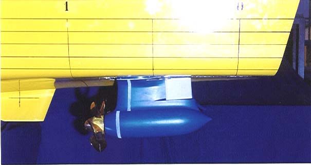
2

Alternative Propulsion Concepts for Fast Navy Ships
Part II: Podded drives for navy ships

Dipl.-Ing. H.-J. Heinke     Schiffbau-Versuchsanstalt Potsdam GmbH

1. Introduction

The interest for the use of podded drives as the main propulsion system of ships is increasing due to
the hydrodynamic characteristics and the advantages of the diesel-electric propulsion. The main
characteristic of podded drives is the integration of a powerful electric motor in a hydrodynamic
optimised gondola below the aft body. The propeller is driven directly by the electric motor. The
following podded drive systems are available in this moment: AZIPOD® (ABB), MERMAIDTM
(KaMeWa/Cegelec), SSP (Schottel/Siemens), DOLPHIN (John Crane Lips/STN).

The possibilities of using podded drives for fast ships from the hydrodynamic point of view will be
discussed in the paper. Studies for the Federal Office of Defence Technology and Procurement (BWB)
about podded drives included the design of pod housings, CFD calculations and different model tests
[1], [2]. It could be shown, that the interaction effects between propeller and pod housing are very
important for the propulsion and the cavitation behaviour of the podded drive. Tests demonstrated the
excellent manoeuvrability of the ship with podded drives.

2. Geometric parameters of the pod housing

The parameters of the pod housing are determined by the necessary installations (electric motor,
bearings, seals, ...). Figure 1 shows the main parameters of a podded drive from the hydrodynamic
point of view.

                                                       Length of the gondola            lG     [m]
                                                       Length ratio                     lG/D   [-]
                                                       Diameter of the gondola          dG     [m]
                                                       Diameter ratio                   dG/D   [-]
                                                       Clearance between propeller
                                                       plane and steering axis          b      [m]
                                                       Clearance ratio                  b/D    [-]
                                                       Length of the strut              C      [m]
                                                       Wetted surface                   S      [m²]
                                               D
                       dG

                  lG
Figure 1: Parameters of a podded drive (Figure of the Azipod from [3])

3. Characteristic of podded drives

The working propeller at the pod housing (gondola and strut) effects an interaction between the
propeller and the housing. The interaction effect is based essentially on the inhomogeneous flow
distribution in the propeller plane, induced by the strut and gondola and the resulting pressure
distribution around the pod housing. Additional the development of the propeller flow of a pulling
propeller is influenced by the pod housing. The hydrodynamic characteristic of the propeller at the
housing is changing in comparison with the propeller in open water condition (Figure 2). The propeller
thrust and torque coefficients are increasing, when the propeller is working in front or behind the pod
housing. The housing is inducing a resistance and the total thrust of the podded drive will be in the
range of the thrust of the free running propeller.

              Podded drives for navy ships, STG-Sprechtag, Potsdam, September 2001
3

The changing of the propeller characteristics and the total efficiency of the podded drive depend
distinctly from the pod housing geometry.

                                 1.0                                                                                                                               Advance coefficient
                                                                                                                                                                            V
                                 0.9                                                                                                                                    J= A
                                                                                                                                                                           n ∗D
                                                                                                                          _______
                                                                                                                                    propeller with pod
                                                                                                                          - - - - - free running propeller
                                 0.8

                                 0.7
                                                                                                                                                                   Propeller thrust coefficient
                                                                                10KQ                                                                                             TP
 KTP, KTT, KTPod, 10KQ, ηT [-]

                                                                                                              ηT
                                 0.6                                                                                                                                 K TP =
                                                                                                                                                                            ρ ∗ n2 ∗ D 4
                                 0.5
                                                                    KTP
                                                        KTT
                                 0.4                                                                                                                               Total thrust coefficient
                                                                                                                                                                             T +T
                                 0.3                                                                                                                                 K TT = P 2 Pod4
                                                                                                                                                                             ρ ∗n ∗D
                                 0.2

                                 0.1                                                                                                                               Propeller thrust coefficient
                                                                                                                                                                                QP
                                 0.0
                                                                                KTPod                                                                                 KQ =
                                 -0.1
                                                                                                                                                                            ρ ∗ n2 ∗ D5
                                        0.0   0.1     0.2     0.3         0.4       0.5   0.6           0.7    0.8       0.9        1.0   1.1     1.2        1.3
                                                                                                J [-]                                                              Total efficiency
Figure 2: Open water characteristic of a podded drive                                                                                                                         J K TT
                                                                                                                                                                      ηT =      ∗
          with a pulling propeller                                                                                                                                           2π K Q

4. Influence of pod parameters on the open water characteristic

The knowledge of the influence of different parameters of the podded drive at the propeller thrust and
torque and at the total thrust is necessary for the design and optimisation of the propulsion system.

Thrust loading coefficient of the propeller

The interaction of the propeller with the pod housing and the influence of the pod housing on the total
efficiency of the system is strongly increasing for thrust loading coefficients CTP ≤ 1.3 (Figures 3 to 5).
The propeller thrust loading coefficients for fast navy ships are often smaller than CTP = 0.8.

Gondola diameter

The pod diameter ratio dG/D is the most important parameter for the pod housing design. The
increasing of the pod diameter results in an increasing of the propeller thrust and torque and in a
decreasing of the total efficiency. The relation between the total thrust and the propeller thrust is
decreasing with the increasing of the pod diameter ratio (Figures 3 and 4). The test results show, that
the pod diameter should be small, especially for podded drives with low thrust loading coefficients.

Length of the gondola

The influence of the gondola length on the coefficients of the propeller and the podded drive is small at
the steering angle ψ = 0°. The length of the gondola has to be taken into consideration at steering
angles ψ ≠ 0° (increasing of the resistance and the transverse force). The gondola length is an
important parameter in connection with the minimising of the gondola diameter and the optimisation of
the gondola shape. The length of the gondola is limited due to the maximum steering moments and
the installation condition in the after ship.

Strut

The influence of a slim strut with c/t > 2 ... 3 on the characteristic of the podded drive is small at the
steering angle ψ = 0°. The strut area is important for the resistance and transverse force at steering
angles ψ ≠ 0°. The clearance between the propeller and the strut should be optimised considering the
interaction effects between the propeller and strut and the steering moment.

                                                    Podded drives for navy ships, STG-Sprechtag, Potsdam, September 2001
4

                 1.00
                                  ________
                              A             dG/D = 0.40, lG/D = 0.85
                 0.95         B -- - -- - dG/D = 0.50, lG/D = 1.15
                 0.90         C - - - - - - dG/D = 0.60, lG/D = 1.40
                                  __ __ __
                              D              dG/D = 0.70, lG/D = 1.70
                 0.85

                 0.80

                 0.75
     TT/TP [-]

                                                      A
                 0.70
                                                              B                                  Pull propeller at different pods
                 0.65                                             C
                                                                      D
                 0.60

                 0.55

                 0.50

                 0.45

                 0.40
                        0.1                                                       1.0                                               10.0
                                                                                 CTP [-]

Figure 3: Relation between total and propeller thrust for a pulling propeller
          with different gondolas (results of systematic tests in the SVA Potsdam [4])

            1.00

            0.95

            0.90
                                         1
            0.85                                                                                           1
                                                2
            0.80
                                                                                                      dG/D = 0.42, lG/D = 1.10
TT/TP [-]

            0.75
                                                          3                                            2
            0.70
                                                                                                      dG/D = 0.485, lG/D = 2.16
            0.65

            0.60                                                                                           3

            0.55                                                                                      dG/D = 0.595, lG/D = 3.41

            0.50
                   0.0               0.2            0.4       0.6         0.8    1.0       1.2       1.4       1.6     1.8          2.0
                                                                                CTP [-]

Figure 4: Relation between total and propeller thrust for different podded drives
          with a pushing propeller [5]

Propeller arrangement

The Figures 4 and 5 show test results from Karafiath and Lyons [5] with podded drives with pushing
and pulling propellers. The influence of the gondola diameter of a pushing pod system on the thrust
ratio TT/TP is similar to the results with pulling pod systems (Figure 3).

The resistance of the pod housing is higher for a pulling pod system in comparison with a pod with a
pushing propeller (Figure 5). The pod housing is arranged in the propeller stream for the pod with a
pulling propeller and the flow is characterised due to high axial and tangential velocity components.

The steering moment of a podded drive with a pulling propeller is distinctly higher than for a podded
drive with a push propeller (comparison for a constant distance ratio b/D between the propeller plane
and the z-axis for both systems).

                                       Podded drives for navy ships, STG-Sprechtag, Potsdam, September 2001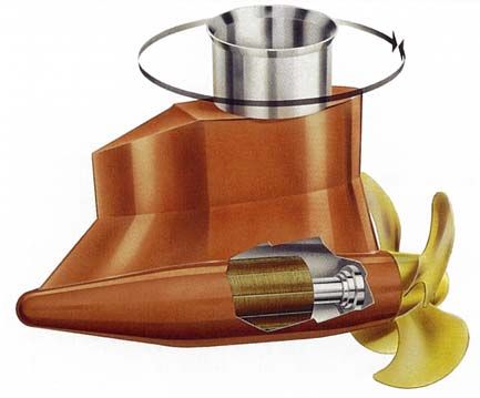
5

The inflow of the pushing propeller is characterised by a small wake peak behind the strut. The
clearance between the strut and propeller should be great enough to minimise a cavitation danger at
the propeller root.

The analysis of the different main parameters of the podded drive shows in connection with the
propeller arrangement at the pod that the type of the pod propulsion system for a fast navy ship has to
be investigated carefully.

            1.00
                                     Push propeller at the pod
                                     dG/D = 0.42, lG/D = 1.10
            0.95

            0.90
                                        Pull propeller at the pod
TT/TP [-]

                                        dG/D = 0.42, lG/D = 1.15
            0.85
                                                                                    Push propeller

            0.80

            0.75
                                                                                    Pull propeller

            0.70
                   0.0   0.2   0.4      0.6     0.8      1.0        1.2       1.4         1.6        1.8     2.0
                                                        CTP [-]

Figure 5: Relation between total and propeller thrust for a push and a pull propeller
          arrangement at the pod [5]

5. Corvette with pulling pod systems

The use of podded drives in connection with the diesel-electric propulsion concept gives new
opportunities for the ship design and the ship propulsion. To study the hydrodynamic effects of pod
propulsion systems for fast navy ships, a corvette had equipped with two podded drives. Figure 6
shows a picture of the arrangement of the podded drives at the after ship. The pod system was
designed in co-operation with SCHOTTEL for a delivered power of PD = 7500 kW. A flap was
integrated in the strut for manoeuvring modes without turning the podded drives.

                                                                                                           Main parameters of the ship
                                                                                                           LPP   [m] :      81.50
                                                         Flap                                              B     [m] :      12.20
                                                                                                           T     [m] :        3.20
                                                                                                           ∇     [m³] : 1385.74
                                                                                                           CB    [-] :        0.482

                                                                                                           Main parameters of the pod
                                                                                                           dG/D [ - ] :       0.555
                                                                                                           lG/D [ - ] :       1.74

Figure 6: Ship model with podded drives

Open water, propulsion, manoeuvring and cavitation tests have been carried out with the model of the
corvette with two podded drives, to study the advantages and disadvantages and to define the
necessary development steps for the use of podded drives for fast navy ships.

                          Podded drives for navy ships, STG-Sprechtag, Potsdam, September 2001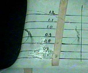
6
Propeller inflow
The wake field measurements show, that a relative homogeneous propeller inflow can be achieved
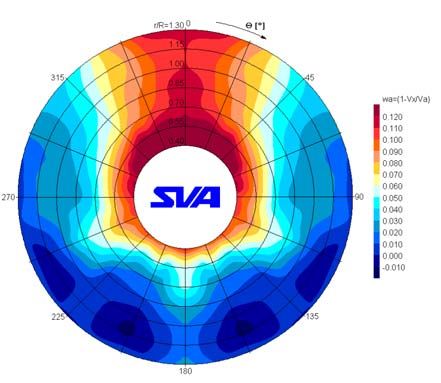
due to the design of the aft ship and the optimum arrangement of the podded drive (Figure 7). The
position of the podded drive at the aft ship had been optimised due the inclination in the vertical and
horizontal direction (inclination angle 3.1° to the basis line and 1.2° rudder angle). In addition velocity
measurements have been carried out in the propeller plane of the pulling propeller with the pod
housing (Figure 8). The flow is rising in the propeller plane of the pull propeller and wake fraction
coefficients up to wa = 0.12 have to be taken into consideration for the propeller design.
Figure 7: Propeller inflow Figure 8: Axial velocity components
(wake field of the ship) (wa = 1- VX/VA) in the pulling
propeller plane
Power requirement
The replacing of the long open shafts, struts and rudders by podded drives reduces the appendage
drag (Figure 9).
16000
14000
model with appendages, with rudder
∆PET = 2000 kW
12000
model with appendages, without rudder
10000
PET [kW]
8000
model without appendages
6000
4000
2000
0
5 10 15 20 25 ∆V = 5 kts 30 35
VS [kts]
Figure 9: Influence of appendages on the towed power
The design of the propeller is a part of the optimisation of the podded drive. The main task is a high
total efficiency and a good cavitation behaviour of the podded drive system. The total efficiency of
pulling podded drives with gondola diameters greater than dG/D = 0.50 is smaller than the efficiency of
the conventional propeller. The total efficiency of the podded drive for the corvette should be in the
Podded drives for navy ships, STG-Sprechtag, Potsdam, September 20017
range ηT > 0.63. In this case the power requirement for the corvette with podded drives will be similar
in comparison with the corvette with a conventional propulsion system (Figure 10).
18000
16000
M 988 Z 040 with podded drives
∆PD = 2000 kW
M 988 Z 040 with conventional propulsion system
14000
12000
PD [kW]
10000
PD
8000
6000
4000
2000
0
12 14 16 18 20 22 24 ∆VS = 2 kts
26 28
VS [kts]
Figure 10: Comparison of the power requirement for a corvette
with podded drives and with a conventional propulsion system
Manoeuvrability
The manoeuvrability of the corvette was tested with the pods and with the flaps at the struts only. The
rules of the IMO 751 were used for the valuation of the test results.
The navigation with pods has been investigated by 10/10 and 20/20 zigzag tests. The corvette was
realising the heading deviation in a short time. The corvette needs for 10° heading deviation at 10°
pod angle 1.05 ship lengths at 12 kts and 1.10 ship lengths at 18 kts (admissible values 2.5 ship
lengths (IMO)). The first and second overshoot angles are very low in comparison with the admissible
values corresponding to the IMO (table 1).
Table 1: Overshoot angles at zigzag tests, steering with pods
Ship speed Angles of zigzag tests Test result IMO Ratio
VS = 12 kts first at 10/10 3.0° 11.6° 25.9 %
VS = 12 kts second at 10/10 3.3° 26.6° 12.4 %
VS = 12 kts first at 20/20 8.5° 25.0° 34.0 %
VS = 18 kts first at 10/10 3.9° 10.0° 39.0 %
VS = 18 kts second at 10/10 4.0° 24.4° 16.4 %
VS = 18 kts first at 20/20 -- 25.0° --
The navigation with flaps only has been investigated with 10/3 zigzag tests. The corvette needs for 3°
heading deviation at 10° flap angle 1.03 ship lengths at 12 kts and 1.26 ship lengths at 18 kts. The
overshoot angles are presented in the table 2.
Table 2: Overshoot angles at zigzag tests, steering with flaps
Ship speed Angles of zigzag tests Test result
VS = 12 kts first at 10/3 1.9°
VS = 12 kts second at 10/3 1.1°
VS = 18 kts first at 10/3 1.5°
VS = 18 kts second at 10/3 1.3°
Podded drives for navy ships, STG-Sprechtag, Potsdam, September 20018
The turning circles have been measured for steering with the pods and the flaps only at three different
ship speeds. The values advance and tactical diameter are important. The IMO presents an
admissible advance of 4.5 ship lengths and an admissible tactical diameter of 5 ship lengths. The
table 3 shows a comparison of the test results with the IMO rules. It can be seen that the turning
circles of the corvette steering with pods are less than 50% of the admissible turning circle.
If the corvette is navigating with the flaps only, the turning circles are 1.5 – 3 times greater than the
admissible turning circles. The flaps are useful for heading deviation at sea but not for the estuary
trading.
Table 3: Turning circles, steering with pods or with flaps
Ship speed Steering angles Test result Admissible Ratio
steering with pods advance/Lpp 1.8 4.5 40 %
VS = 6 kts
ψ = 35° tactical diameter/Lpp 1.8 5 36 %
steering with pods advance/Lpp 1.9 4.5 42 %
VS = 12 kts
ψ = 35° tactical diameter/Lpp 1.7 5 34 %
steering with pods advance/Lpp 1.9 4.5 42 %
VS = 18 kts
ψ = 35° tactical diameter/Lpp 1.7 5 34 %
pods ψ = 0°, steering advance/Lpp 5.2 4.5 115 %
VS = 6 kts
with flaps δF = 30° tactical diameter/Lpp 8.4 5 168 %
pods ψ = 0°, steering advance/Lpp 5.7 4.5 127 %
VS = 12 kts
with flaps δF = 30° tactical diameter/Lpp 9.1 5 182 %
pods ψ = 0°, steering advance/Lpp 9.2 4.5 204 %
VS = 18 kts
with flaps δF = 30° tactical diameter/Lpp 15.4 5 308 %
Cavitation behaviour
Cavitation tests have been carried out with the podded drive in the great test section of the cavitation
tunnel. The three-dimensional wake field, calculated for the full-scale has been simulated with a
dummy model. The arrangement of the podded drive at the stern is similar to the full-scale ship.
The cavitation behaviour of the propeller and in addition at the pod housing has to be noted for a
pulling pod system. The tip vortex of the propeller is cavitating if the pressure in the tip vortex is further
decreasing due to the flow around the strut (Figure 11). There is an oblique inflow to the shaft due to
the twist in the propeller stream. The region of low pressure at the suction side of the strut could be a
starting point for sheet and bubble cavitation especially at high ship speeds (Figure 12). A reduction of
the low pressure can be realised due to a chamber of the strut. The Figures 12 and 13 are showing
the cavitation at the shaft for the same working point. The sheet cavitation had been eliminated due to
the optimisation of the strut (asymmetric profile).
Fig. 11: Cavitating tip Fig. 12: Sheet cavitation Fig 13: Cavitation at an
vortex at the strut at the strut optimised strut
6. Summary
Podded drives for navy ships, STG-Sprechtag, Potsdam, September 20019
The investigations about the use of podded drives for fast navy ships have shown, that an use of
these new propulsions systems is possible from the hydrodynamic point of view. Advantages of a ship
with podded drives are for example a free engine arrangement, a better manoeuvrability and an
optimum propeller inflow. A propeller design with a good cavitation characteristic and reduced
propeller induced pressure fluctuations and vibrations is possible.
The necessary power of the tested corvette with two podded drives (dG/D > 0.50) is nearly comparable
with the power of the corvette with the conventional propulsion system. A smaller gondola diameter
(dG/D = 0.40 … 0.45) results in a higher total efficiency and a reducing of the interaction effects
between propeller and pod housing. That’s why the minimisation of the gondola diameter is an
important task.
Further hydrodynamic investigations should include the optimisation of the gondola shape, especially
the range behind the hub of a pulling propeller. The clearance between the pulling propeller and the
strut should be optimised and the use of podded drives with pushing propellers should be studied.
The main tasks for the constructive work are the minimising of the weight, the investigation of the
noise generation and of the electro-magnetic field as well as the guarantee of shock loads.
7. References
[1] Heinke, H.-J., Manke, H. et al.
Studie – Erprobung eines SIEMENS-SCHOTTEL-Propulsors für die Korvette
Report No. 2542, Potsdam, July 1999 (unpublished)
[2] Heinke, H.-J., Abdel-Maksoud, M. et al.
Studie - Definition der baulichen Zielgrößen für Podded Drives
Report No. 2537, Potsdam, November 1999 (unpublished)
[3] J. Andersson, S. Eloranta et al.
B-MAX A new approach in roro design
RoRo98 Conference May 12-14, 1998 – Gothenburg
[4] Heinke, H.-J.; Bohm, M.
Analysis of the design concept for the Lips pod geometry and propeller data
Report No. 2405, Schiffbau-Versuchsanstalt Potsdam, July 1998 (unpublished)
[5] Karafiath, G. Lyons, D.
Pod Propulsion Hydrodynamics – U.S. Navy Experience
Fifth International Conference On Fast Sea Transportation (FAST ’99), Seattle, Washington
USA, August 31 – September 2, 1999
Acknowledgements
The author would like to express his gratitude to the Federal Office of Defence, Technology and
Procurements, Department Ships and Naval Equipment for the support of the studies about podded
drives for navy ships and the permission to publish this paper.
Podded drives for navy ships, STG-Sprechtag, Potsdam, September 2001You can also read