Hecla Greens Creek Mining Company's Surface Exploration Plan of Operations - 2017 through 2021
←
→
Page content transcription
If your browser does not render page correctly, please read the page content below
Hecla Greens Creek Mining Company’s Surface
Exploration Plan of Operations - 2017 through 2021
Submitted to the United States Forest Service, Juneau Ranger District, Tongass
National Forest, Alaska.

Prepared by Hecla Greens Creek Mining Company.

April 15, 2016

Photo of helipad on Gallagher Ridge overlooking Hecla’s Greens Creek Mine, taken by
exploration personnel.

For More Information Contact:
Chris Wallace, Environmental Manager
Hecla Greens Creek Mining Company
P.O. Box 32199, Juneau, AK
Phone: 907-790-8473
Email: cwallace@hecla-mining.com
Plan of Operations for Hecla Greens Creek Mining Company’s
                     Surface Exploration Plan 2017-2021

                                                     Table of Contents

Table of Contents ............................................................................................................................ ii
List of Figures ................................................................................................................................ iv
List of Tables .................................................................................................................................. iv
List of Abbreviations and Acronyms .............................................................................................. v
Chapter 1 Introduction..................................................................................................................... 1
   1.1 Project Title and Name of Applicant .................................................................................... 1
   1.2 Project Location .................................................................................................................... 1
   1.3 Project Overview................................................................................................................... 1
   1.4 Project Schedule .................................................................................................................... 2
  1.5 Purpose .................................................................................................................................. 3
  1.5 Conformance with Statute and Regulations .......................................................................... 3
Chapter 2 Applicant Information..................................................................................................... 7
  2.1 Applicant Contact Information ............................................................................................. 7
  2.2 Surface and Mineral Ownership............................................................................................ 7
  2.3 Right of Entry........................................................................................................................ 7
Chapter 3 Geology and Mineralization ........................................................................................... 7
Chapter 4 Exploration Activities ..................................................................................................... 8
  4.1 Access ................................................................................................................................... 8
  4.2 Helicopter Use....................................................................................................................... 8
  4.3 Geologic Mapping............................................................................................................... 10
  4.4 Soil Surveys ........................................................................................................................ 11
  4.5 Geophysical Surveys ........................................................................................................... 11
     4.5.1 Heli-Airborne Electro-magnetic (EM) surveys ............................................................ 11
     4.5.2 Ground EM surveys ...................................................................................................... 13
     4.5.3 Ground IP surveys ........................................................................................................ 14
     4.5.4 Ground Gravity surveys ............................................................................................... 14
     4.5.5 Heli-Airborne Gravity Gradiometry surveys ................................................................ 14
     4.5.5 Borehole EM surveys ................................................................................................... 15
  4.6 Diamond Drilling ................................................................................................................ 15
     4.6.1 Drill Site Preparation .................................................................................................... 15
     4.6.2 Drilling Water Supply .................................................................................................. 17
     4.6.3 Drilling Activities ......................................................................................................... 20
     4.6.4 Materials and Drilling Additives .................................................................................. 21
     4.6.5 Hole Abandonment ....................................................................................................... 24
     4.6.6 Drill Site Reclamation .................................................................................................. 24
  4.7 Spill Prevention and Waste Disposal .................................................................................. 25
     4.7.1 Spill Prevention Control and Countermeasures (SPCC) .............................................. 25
     4.7.2 Fuel transport and storage ............................................................................................ 25
Chapter 5 Mitigation and Monitoring............................................................................................ 28
  5.1 Introduction ......................................................................................................................... 28
  5.2 Air Quality and Noise ......................................................................................................... 28
  5.3 Geotechnical Stability ......................................................................................................... 29

                                                                                                                                        Page | ii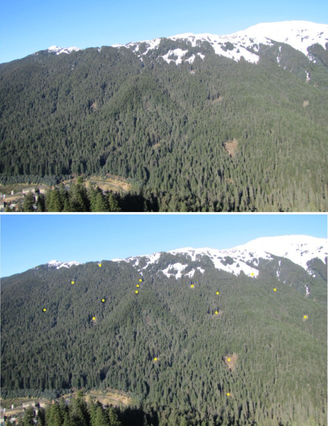
5.3.1 Erosion.......................................................................................................................... 29
    5.3.2 Slump control ............................................................................................................... 29
  5.4 Water Resources ................................................................................................................. 30
    5.4.1 Surface Water ............................................................................................................... 30
    5.4.2 Ground Water ............................................................................................................... 35
  5.5 Geochemistry ...................................................................................................................... 37
  5.6 Aquatic Resources............................................................................................................... 38
  5.7 Soils..................................................................................................................................... 39
  5.8 Vegetation ........................................................................................................................... 39
    5.8.1 Ground Cover and Shrubs ............................................................................................ 39
    5.8.2 Trees ............................................................................................................................. 40
    5.8. Invasive Species ............................................................................................................. 43
  5.9 Wetlands.............................................................................................................................. 43
  5.10 Common Wildlife ............................................................................................................. 45
  5.11 Threatened and Endangered Species ................................................................................. 45
  5.12 Land Use ........................................................................................................................... 46
  5.13 Scenic Resources............................................................................................................... 47
  5.14 Recreation ......................................................................................................................... 48
  5.15 Subsistence ........................................................................................................................ 49
  5.16 Cultural Resources ............................................................................................................ 49
  5.17 Socioeconomics ................................................................................................................ 49
  5.18 Monument Resources ........................................................................................................ 49
  5.19 Inventoried Roadless Areas (IRA’s) ................................................................................. 50
  5.20 Solid Wastes...................................................................................................................... 50
References ..................................................................................................................................... 51
Appendix A – HGCMC’s Standard for Helicopter Operations ..................................................... 53
Appendix B – HGCMC’s Standard Task Description for Line Cutting........................................ 64
Appendix C – HGCMC’s Temporary Water Use Authorizations ................................................. 66
Appendix D – HGCMC’s Driller Environmental Checklist ......................................................... 71

                                                                                                                                      Page | iii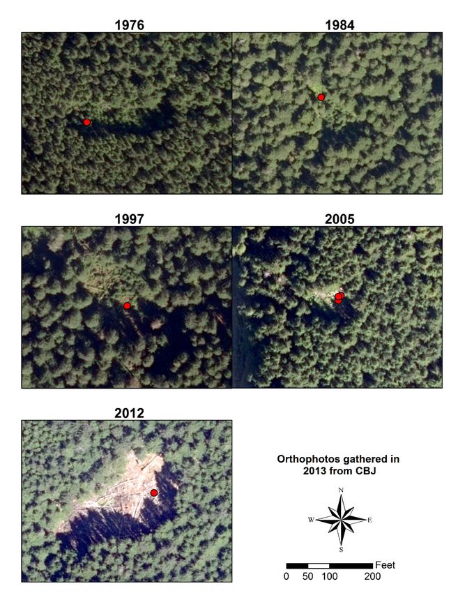
List of Figures
Figure 1-1. Location Map .................................................................................................. 5
Figure 1-2. Areas of interest for drilling activities. ............................................................ 6
Figure 4-1. Location of infrastructure ................................................................................. 9
Figure 4-2. Typical disturbance for outcrop mapping...................................................... 10
Figure 4-3. Example of soil auger and typical sample......................................................11
Figure 4-4. Heli-EM survey. ............................................................................................ 12
Figure 4-5. Ground EM survey. ....................................................................................... 13
Figure 4-6. Drilling pad construction site in timbered area. ............................................ 16
Figure 4-7. Flyable backhoe. ........................................................................................... 17
Figure 4-8. Drill site layout.............................................................................................. 18
Figure 4-9. Map of streams designated for temporary water use. ................................... 19
Figure 4-10. Typical Diamond Drill Setup at Greens Creek............................................ 21
Figure 4-11. Mud filter cake influencing drill waters. ..................................................... 22
Figure 4-12. Location of Jet-A fuel tanks and pumps for fueling helicopters. ................ 27
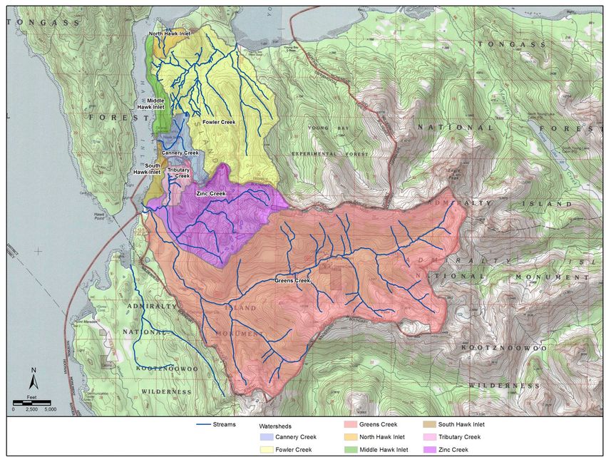
Figure 5-1. Watersheds of the Greens Creek area. ........................................................... 34
Figure 5-2. Drill site after 38 years of regrowth. ............................................................. 41
Figure 5-3. 2013 orthophoto of drilling sites showing regrowth. .................................... 42
Figure 5-4. USFWS National Wetlands Inventory relative to AOI’s. .............................. 44
Figure 5-5. Hill slope showing historic drilling sites. ...................................................... 48
List of Tables
Table 1-1. Maximum yearly surface disturbance by exploration activity. ......................... 2
Table 4-1. Typical drilling additives for HGCMC surface drilling programs.................. 23
Table 5-1. Summary of air pollution and noise sources................................................... 28
Table 5-2. Surface water risks and protective measures. ................................................. 30
Table 5-3. Spill reporting requirements. .......................................................................... 33
Table 5-4. Groundwater risks and protective measures. .................................................. 37
Table 5-5. Land types within the AOI’s. .......................................................................... 40
Page | iv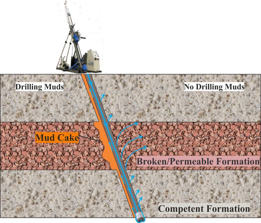
List of Abbreviations and Acronyms

                     Acronyms and Abbreviaions
ADEC      Alaska Department of Environmental Conservation
AK        State of Alaska
AKDNR     Alaska Department of Natural Resources
AMD       Aviation Management Directorate (formerly OAS)
ANILCA    Alaska National Interest Lands Conservation Act of 1980
ANSI      American National Standards Institute
AOI       Area of Interest
CBJ       City and Borough of Juneau
CFR       Code of Federal Regulations
DOT       US Department of Transportation
EIS       Environmental Impact Statement
EM        Electro-Magnetic
FAA       Federal Aviation Administration
FSH       Forest Service Handbook
FWMP      Fresh Water Monitoring Plan
gpm       Gallons per minute
GPS       Global Positioning System
HDPE      High Density Polyethylene
HGCMC     Hecla Greens Creek Mining Company
in        Inches
IP        Induced Polarization
IRA       Inventoried Roadless Area
kW        Kilowatt
LCZ       Lost Circulation Zone
LUD       Land Use Designation
NEPA      National Environmental Policy Act
NFPA      National Fire Protection Association
NPDES     National Pollutant Discharge Elimination System
NSF       National Sanitation Foundation International
OAS       Office of Aircraft Services
OSPAR     Oslo Paris Convention
PLONOR    Pose Little or No Risk
psi       Pounds per square inch fluid pressure
SIO       Scenic Integrity Objective
SPCC      Spill Prevention, Control, and Countermeasure
sqft      Square feet
TWUA      Temporary Water Use Authorization
USFS      United States Forest Service
USFWS     US Fish and Wildlife Service

                                                                    Page | v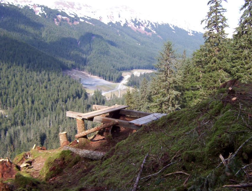
Chapter 1 Introduction
       1.1 Project Title and Name of Applicant
Hecla Greens Creek Mining Company (HGCMC) is the applicant for this mineral
exploration program identified as the Greens Creek Surface Exploration Plan of
Operations – 2017 through 2021 (exploration plan), and will be responsible for the
activities pertaining thereto.

       1.2 Project Location
HGCMC proposes to conduct mineral exploration activities adjacent to their operating
Greens Creek Mine within the Greens Creek Land Exchange and on their Federal lode
mining claims located on Admiralty Island, AK (Figure 1-1). HGCMC’s land package
totals over 24 square miles, referred to herein as the ‘project area,’ with the southern half
being the Land Exchange and the northern half being Federal lode mining claims.
Within the project area, smaller ‘areas of interest’ (AOI) have been identified. Drilling
activities will be limited to the two AOI’s shown on the map in Figure 1-2. Geophysical
surveys, geologic mapping and soil sampling will extend outside the AOI boundaries, but
will remain within the project area.
These AOI’s have been considered within the 1983 Environmental Impact Study (EIS)
completed for HGCMC’s mine and mill. The 2003 and 2013 Greens Creek Tailings
Facility Expansion EIS’s envisioned exploration activities as part of impact analyses.
Many smaller wildlife and botany surveys have also been completed in these areas for the
permitting of past drilling programs.

       1.3 Project Overview
The exploration plan will explore over the next five years for silver, zinc, lead and gold
rich volcanogenic massive sulfide mineralization as is present at the Greens Creek Mine.
Past work has identified geologic and geochemical targets which require further work in
order to determine whether minable resources are present or not. Some of the targets
require further field mapping and soil sampling while others are ready for geophysical
surveying or drill testing to provide subsurface information. Table 1-1 summarizes
activities within the exploration plan.
Of the proposed activities, diamond core drilling is most essential. As some targets reach
4,000 feet in depth, drilling equipment must be capable of that depth. Only road based
drills, or larger, flyable core drilling rigs can complete holes that deep. Road based rigs
have been excluded as a possible alternative to avoid road construction. Helicopters will
be used for transporting crews, equipment and supplies to minimize impacts.
To protect sensitive species, HGCMC will contract third party plant and wildlife surveys
for each drilling site before entry, and submit the findings to the Forest Service for
review. Where sensitive species are identified, appropriate buffer zones will be

                                                                                      Page | 1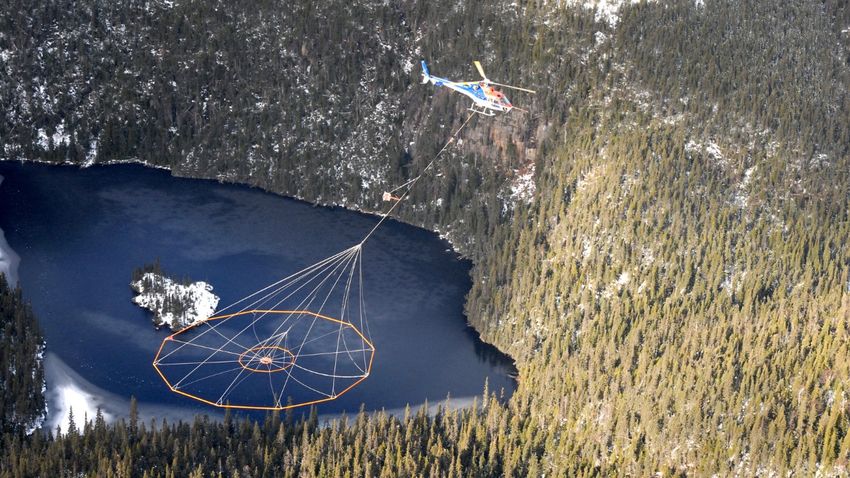
maintained to minimize disturbance. Reclamation activities will immediately follow
drilling, according to best management practices, to ensure surface and ground waters are
protected, erosion prevented and natural vegetation restored. A yearly activity and
reclamation report will document these efforts to the Forest Service, and provide status
on reclaimed drilling sites for two years.
Exploration targets evolve every year as geologic information is continually gathered and
analyzed. Therefore, the exact location of each drilling site is not known more than a
year in advance. However, core drilling activities will be: 1) limited to specific areas of
interest, 2) committed to less than 5 acres land disturbance per year and 3) described in
terms of procedures and annual reclamation. By presenting all potential activities in this
manner, it is desired that this 5-year plan of operations be considered in an Environmental
Assessment.

Table 1-1. Maximum yearly surface disturbance by exploration activity.
 Exploration
 Activity           Description                      Maximum Disturbance

 Core drilling           Clearing drilling sites of trees    Less than 5 acres

                                                             Less than 0.12 acres of total
 Core drilling           Building pads and sumps             excavation within drilling sites,
                                                             reclaimed annually

                         6 inch diameter holes to 'C' soil   Less than 550 samples, or 0.01
 Soil sampling
                         horizon                             acres, reclaimed immediately

                         Up to 3-square feet of moss         Less than 50 locations, or 0.01
 Geologic mapping
                         removed from outcrop if needed      acres
                         2.5 foot wide footpath cleared of
 Ground geophysical                                          Less than 10 miles of footpath
                         brush and small (< 2-inch) trees
 surveys                                                     cleared
                         and branches
 Airborne
                         None                                None
 geophysical surveys

       1.4 Project Schedule
These activities are planned for a period of five years, beginning in May of 2017 and
ending in September of 2021. Typically the field season does not begin until May and
ends before September, but if the economic environment and weather provide an
opportunity to start earlier or end later, operations may start as early as March 1 and
continue until October 31.

                                                                                    Page | 2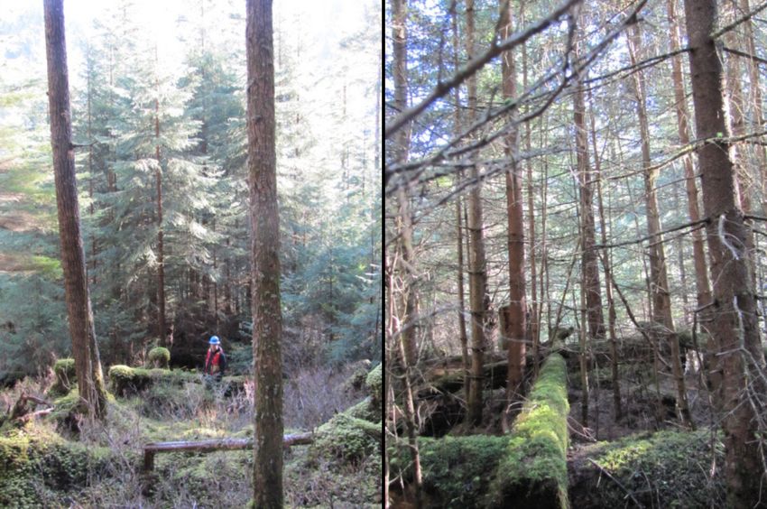
To keep within Forest Service Handbook guidelines, yearly notifications will be made to
the Forest Service by December 15 regarding the location of each planned drill site for
the next year (FSH 2509.22_10). At the same time, an activity and reclamation report
will be submitted for the current year’s activities.

       1.5 Purpose
As of 2015 the Greens Creek Mine has mined 264,046,360 ounces of silver, 2,278,374
ounces of gold, 1,631,200 tons of zinc and 638,989 tons of lead over its 27-year history.
Currently, the mine has 8 to 12 years of minable resources. In order to support further
mining, additional resources must be found.
Though underground exploratory drilling has been successful in adding to the mine’s life
historically, that drilling can only effectively test areas less than 2,000 feet from existing
mine infrastructure. Targets further afield must be tested by surface drilling. This
proposed exploration plan will allow for testing of existing mineralized targets and
generation of new targets not accessible from underground operations. If mineable
horizons are intercepted in drilling, the objective would be to turn these into mineral
reserves for the mine.

The Greens Creek Mine is Juneau’s largest private employer, with 415 employees and an
annual payroll and benefits of over $68 million in 2015. Annual purchasing from
Alaskan businesses has averaged over $45 million per year over the last five years. It is
estimated that the Greens Creek Mine generates an additional 390 indirect jobs in the
Alaskan economy. Only through exploration efforts such as those proposed in this
application can the mine continue in providing this support to the community.

       1.5 Conformance with Statute and Regulations
The proposed exploration plan is supported by the 2008 Land and Resource Management
Plan for the Tongass National Forest (Forest Plan), the Greens Creek Land Exchange Act
of 1995 (Public Law 104-123, 104th Congress), the Alaska National Interest Lands
Conservation Act of 1980 (ANILCA, 16 U.S.C. 3770, Sections 1010 and 1110(b)) and
United States Mining Law (30 U.S.C. Chapter 2). The exploration plan will be regulated
through the Forest Service under 36 CFR part 228, subpart A, to minimize adverse
environmental impacts to surface resources.
The Forest Service’s Juneau Ranger District of the Tongass National Forest and the
Admiralty Island National Monument Ranger District administers and regulates mineral
exploration activities for the project area. Various laws and plans guide their
management including:
   1. The 2008 Forest Plan provides standards and guidelines for permitting and
      performing activities.
   2. ANILCA, sections 810 and 811 protect subsistence activities.

                                                                                       Page | 3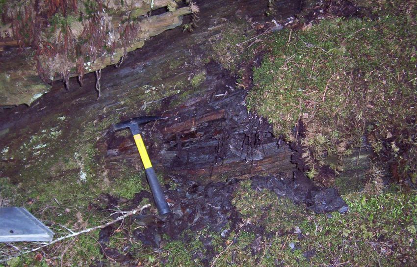
3. The Endangered Species Act of 1973 provides protection for endangered species,
   though no federally listed threatened or endangered species are known to exist in
   the project area.
4. The Magnuson-Stevens Fishery Conservation and Management Act protects
   freshwater and marine habitat essential to fish.
5. The National Historic Preservation Act, section 106, requires the Forest Service to
   consider historic resources, including archeological resources, when reviewing
   permit applications (36 CFR 800).
6. Executive Order 11988 protects floodplains.
7. Executive Order 11990 protects wetlands.
8. Executive Order 12962 protects recreational fisheries.
9. Executive Order 13112 protects against the spread of invasive species.
10. Under Executive Order 12088 and Section 313 of the Clean Water Act, the Forest
    Service (Region 10) has coordinated with the Alaska Department of
    Environmental Conservation (ADEC) in the 1992 Memorandum of Agreement to
    protect water resources on Forest Service System lands in Alaska. That
    agreement set forth the “Forest Service Alaska Regional Water Quality
    Management Plan” which identifies the Forest Service as the regulatory authority
    responsible for monitoring and protecting water quality on National Forest
    System lands in Alaska for purposes of the Clean Water Act (as amended in
    1987). The agreement also specifies responsibilities and activities for the Forest
    Service and for ADEC as described within the Alaska Nonpoint Source Pollution
    Control Strategy and Clean Water Act of 1990.
11. The 1992 Memorandum of Agreement also sets forth the Forest Service’s Soil and
    Water Conservation Handbook (Chapter 10) as the Best Management Practices
    (BMPs) basis for developing procedures to protect water resources, including
    riparian areas and wetlands.
All activities proposed herein are designed in accordance to these plans, laws,
regulations and BMPs.

                                                                                  Page | 4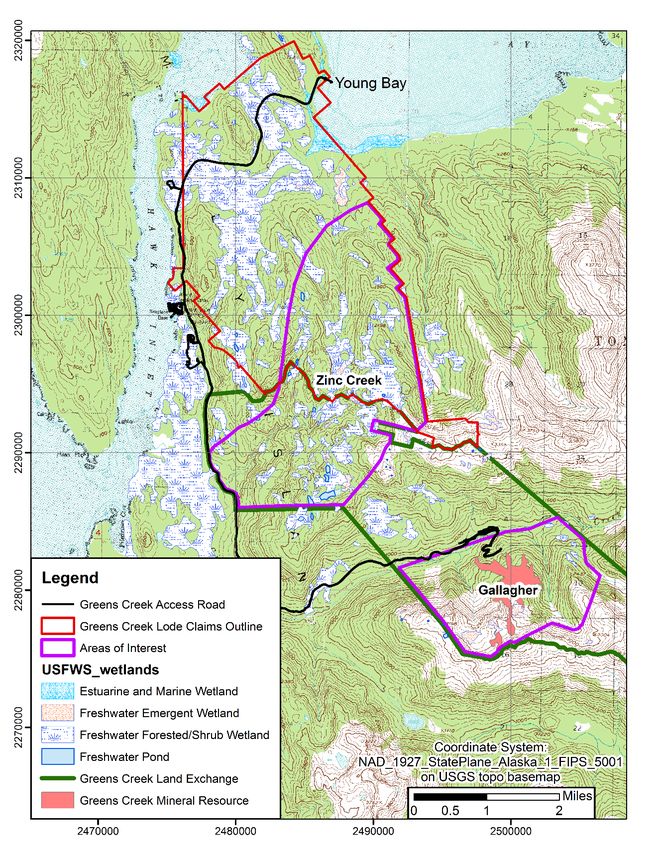
Figure 1-1. Location Map

                           Page | 5
Figure 1-2. Areas of interest for drilling activities.
Page | 6Chapter 2 Applicant Information
2.1 Applicant Contact Information
Chris Wallace, Environmental Manager
Hecla Greens Creek Mining Company
P.O. Box 32199, Juneau, AK
Phone: 907-790-8473
Email: cwallace@hecla-mining.com
2.2 Surface and Mineral Ownership
All activities will be within HGCMC’s 24 square mile land package. The Greens Creek
Land Exchange, comprising the lower half of the land package, allows for mining and
exploration activities (Congress 1996). HGCMC owns seventeen patented lode claims
over the Greens Creek Mine, within the Land Exchange. The northern half of the land
package is comprised of 440 contiguous unpatented federal lode mining claims which
HGCMC controls (Figure 1-2).
2.3 Right of Entry
HGCMC currently has the right to enter the Greens Creek Land Exchange for mineral
exploration as authorized by the Greens Creek Land Exchange Act (1995) and its
associated Greens Creek Land Exchange Agreement (1994). Under the General Mining
Act of 1872, HGCMC personnel have the right to enter public lands such as the 440
federal lode claims for exploration purposes, but cannot perform disruptive work such as
drilling unless granted permission by the Forest Service.
Chapter 3 Geology and Mineralization
The Greens Creek deposit is a polymetallic, stratiform, volcanogenic massive sulfide
deposit with a relatively high precious metal content compared to other deposits of its
type. The host rocks consist predominantly of Triassic marine sedimentary and
Carboniferous basaltic rocks, which have been subjected to multiple periods of
deformation. The latest intense ductile deformation occurred in Middle Cretaceous as the
Alexander terrane collided with the North American continent. That deformation was
followed by large scale, right lateral strike slip faulting. Some of the larger strike slip
faults have more than 1,000 feet of displacement.
Mineralization occurs discontinuously along the contact between the marine sedimentary
sequence and the basaltic sequence of rocks. Sulfide accumulations typically mined
include pyrite, sphalerite, galena and tetrahedrite/tennanite minerals. On the flanks of the
sulfide accumulations barite, carbonate and quartz gangue minerals are abundant. The
original basaltic host rocks are altered hundreds of feet from the mineralization centers,
with carbonates and sericite mica being the predominant alteration minerals.
Page | 7Chapter 4 Exploration Activities
4.1 Access
As the Greens Creek Mine is presently in operation, all necessary piers, docks and roads
are in place and available for support of the exploration plan (Figure 4-1). No new roads
are anticipated as a part of the exploration plan, so the Greens Creek and Mansfield
Peninsula Inventoried Roadless Areas (IRA’s) will not be affected (2001 Roadless Rule,
Forest Service 2000).
Equipment and fuel will be transported to and from the Greens Creek marine terminal at
Hawk Inlet by oceangoing barges. The equipment is then transported via tractor-trailer
over an existing unpaved haul road eight miles to a storage yard (‘860’ laydown) near the
mine portal. As the road is used daily for ore concentrate and tailings haulage, it is well
maintained with guardrails on steep slopes and bridges.
Exploration personnel will be transported via boat from Auke Bay to the pier at Young
Bay. From Young Bay a bus transports personnel to either Hawk Inlet or to the Greens
Creek Mine. The existing man camp at Hawk Inlet will house all staff needing to stay
overnight. A few managerial staff will take the bus and boat to and from Juneau every
day, but the majority of the crews, including the drilling contractor, will stay overnight at
the man camp. As with the road, the man camp is managed under HGCMC’s Plan of
Operations (Forest Service 1983, 1988 and 2013). Crews will be transported from the
man camp to their working area either by the helicopter or by pickup truck on existing
roads.
4.2 Helicopter Use
As no new roads are anticipated for the exploration plan, access to drill stations and other
fieldwork is either by foot from the existing roads or by helicopter. Personnel, materials,
core samples, fuel and equipment will be transported by OAS/USFS certified pilots using
either a Hughes 500 or 600 series helicopter or the larger Eurocopter AS350 (A-star, B-2
or B-3) helicopter.
Typically the A-star is used when moving drilling rigs to and from drilling sites, while the
smaller Hughes helicopter supports day-to-day operations. Typical in-flight times will be
1 to 3 hours per day depending on support required. Moving drills or constructing
drilling pads requires 3 to 7 hours per day depending on site location and weather.
As the fieldwork is remote, the helicopter is the primary mode of transport in case of
safety or environmental emergency. As such, a helicopter and pilot will remain in the
project area day and night. At times the pilot will fly into Juneau for supplies, or to
switch out aircraft, which is a 20-minute flight.
Page | 8Communication with the helicopter pilot(s) will be via handheld radios through a repeater
located centrally within the claim block (Figure 4-1). All staff will be required to have a
Figure 4-1. Location of infrastructure
Page | 9radio on their person or at their working site. The pilot and one other exploration
manager will monitor the radio 24 hours per day, seven days per week.
All exploration personnel will be instructed in helicopter safety. The pilot will provide an
orientation briefing at the helicopter prior to any use of the helicopter. Instructional
videos regarding helicopter safety and slinging operations will be viewed by all
exploration personnel. No person will participate in sling operations until they have been
task trained by competent personnel. Appendix A contains HGCMC’s helicopter safety
manual.
4.3 Geologic Mapping
Helicopter supported geologic mapping will be conducted during the summer months.
Only day hikes will be taken with small packs, with no planned overnight camps. No
trash, equipment or samples will be left overnight. Traverses begin and end at existing
helicopter landing sites or at existing roads.
Crews of two geologists hike through the forest and along streams, taking advantage of
game trails when available. No axes or saws will be used to blaze trail. At rock outcrops
the geologists make observations and often collect a small specimen for further
laboratory work. The specimens will typically weigh less than 1 pound.
Once a traverse has been made it is rare that it will be made again that year, so topsoil is
not disturbed. Two-way radios, compasses, maps and GPS units will be taken in the field
for positioning and in case of emergency. Bear spray and ‘bear banger’ signal cartridges
will be carried as bear deterrent. Firearms will not typically be carried in the field.
No motorized tools or vehicles will be used in the field for this work. Only the
geologist’s rock hammer will be used to scrape dirt or moss off outcrops (Figure 4-2).
Figure 4-2. Typical disturbance for outcrop mapping.
Page | 104.4 Soil Surveys
Like geologic mapping activities (section 4.3), no motorized tools or vehicles will be
used for soil surveying. Field technicians will be flown to the sampling area by
helicopter. The samplers
follow designed grids using
GPS and compass on soil
lines spaced 400 to 1,000
feet apart, depending on the
nature of the target.
A hand augur is used to
collect soil from the ‘C’
horizon every 100 feet along
the soil line (Figure 4-3).
Approximately 1 pound of
soil is collected in a labeled
sample bag. Flagging is
Figure 4-3. Example of soil auger and typical sample. placed close to the sample
location. Tools will be
cleaned, and the augured hole filled and topped with the removed vegetation before
moving onto the next sample location.
4.5 Geophysical Surveys
Several types of geophysical surveying have been used at Greens Creek. Only two
borehole EM surveys have been conducted by HGCMC over the last five years, while no
airborne or surface EM studies were completed in that time. Though geophysical surveys
are uncommon for the Greens Creek claim block in a given year, one or more may occur
as needed over the next five years. Therefore, airborne, ground and borehole surveys will
be included as possible activities.
4.5.1 Heli-Airborne Electro-magnetic (EM) surveys
If an airborne EM survey is commissioned, a helicopter pilot and geophysical technician
will base their activities out of the Hawk Inlet facility. Depending on weather, the
helicopter may fly up to the FAA specified 8 hours in a day.
When flying the survey, the pilot will keep the geophysical instrument approximately 100
feet above treetops. The instrument typically hangs 100 to 150 feet below the aircraft, so
the helicopter is 200 or more feet above the treetops. The flight path would likely be on
parallel lines separated by 200-400 feet with crossing lines separated by 1000-2000 feet.
Flight speed varies according to topography, but would typically be more than 20 miles
per hour at Greens Creek.
Page | 11Any survey flown should be completed in less than five flying days. Notification of any
airborne survey will be made to the Forest Service at least two months in advance.
Figure 4-4 provides an example of a typical Helicopter EM survey. (Geotech Ltd.’s
VTEM system.)
Figure 4-4. Heli-EM survey.
Page | 124.5.2 Ground EM surveys
Ground EM surveys require the placing of a thin insulated wire in a large overland loop
over a target area (Figure 4-5). Loops may be up to 5 miles in length, but typically much
smaller. As the wire loop must be installed by hand, line-cutting crews will be flown by
helicopter into the survey area
with chainsaw, brush ax and
machete to cut a 2.5-foot wide
path where the loop is to lay. No
live trees larger than 2 inches in
diameter will be cut. Fallen logs
will be cut so that a person can
walk through or step over them
safely. Small brush and plants will
be cut using a machete or Sandvik
brush axe to within several inches
of the ground. (Appendix B
contains HGCMC’s line cutting
procedure.)
Once the EM loop is in place, a
field geophysicist transmits an
electric wave through the loop
which causes a magnetic field to
interact with the earth. That field
causes weak currents to flow in the
subsurface according to the rock’s
Figure 4-5. Ground EM survey. properties. A synchronized
receiver coil then picks up the
decay of the magnetic field created by the earth as the induced currents with in it
attenuate. The receiver coil is carried on a backpack by a field technician on traverse
lines over the loop. No line cutting is required for the field technician with the receiver
coil.
The size and number of loops and the spacing of lines traversed with the receiver all
depend on the size and depth of the target as well as the conductivity of the subsurface
rocks. While the dimensions of these loops are not known presently, the total amount of
line cutting for an entire year’s exploration program will not exceed 10 miles. A ten-mile
program would consist of: 1) a crew of two cutting the lines for approximately 35 days,
2) a crew of two placing and retrieving the lines for approximately 10 days and 3) a crew
of three running the transmitter and receiver during data collection for approximately 20
days.
For ground EM surveying, a generator is required to provide the signal for the loop. The
power requirements of the generator are small, so it will typically be a portable 5 kilowatt
(kW) sized model. Generator noise is typically 70-80 decibels under full load. The
Page | 13generator and 10 gallons of gasoline fuel will be kept at least 200 feet from running
streams and in secondary containment.
4.5.3 Ground IP surveys
Induced Polarization (IP) surveys measure the capacity for subsurface rock to hold a
charge by transmitting carefully controlled current into the ground via electrode stakes
and measuring the potential field gradient voltage in nearby stakes. Similar to ground
EM surveys, IP surveys require equipment to be carried into the field and insulated wires
placed over ground; therefore, line cutting is required. Line spacing is determined
according to target properties and required resolution, but as mentioned in section 4.5.2,
no more than 10 miles of line cutting will be carried out for any given year.
For IP surveying, a generator is required to provide the transmitted current. The power
requirements of the generator are small, so it will typically be a portable 5 kW model.
The generator and 10 gallons of gasoline fuel will be kept at least 200 feet from running
streams and in secondary containment.
4.5.4 Ground Gravity surveys
Ground gravity surveys do not need line cutting or generators. A crew of two hikes a line
as in soil surveying (section 4.4). At predetermined positions along the line the
gravimeter and differential GPS equipment is removed from daypacks to take a reading.
The crew occupies each station on the line for a few minutes to allow the instruments to
stabilize and take their readings.
No digging or cutting of vegetation is required to use the instruments. No generator is
required as for the EM and IP surveys, as the instrument passively measures the earth’s
gravitational pull. As the line is typically only hiked once, the impact to plants and soil
are minimized.
4.5.5 Heli-Airborne Gravity Gradiometry surveys
Though past gravity surveys have been ground based at Greens Creek, recent advances in
airborne gradiometry have made this technique attractive. Similar to the Heli-Airborne
EM survey discussed in section 4.5.1, a helicopter would be flown over the target area on
lines spaced 200 to 400 feet apart. The gradiometer would not hang from the aircraft as
in the EM survey, but stay onboard. The helicopter would fly the survey lines
approximately 100 feet above treetops at a rate typically more than 20 miles per hour.
If one of these surveys is commissioned, a helicopter pilot and geophysical technician
will base their activities out of the Hawk Inlet facility. Depending on weather, the
helicopter may fly up to the FAA specified 8 hours in a day.
Any survey flown should be completed in less than five flying days. Notification of any
airborne survey will be made to the Forest Service at least two months in advance.
Efforts will be made to schedule the survey around other sensitive studies the Forest
Service may have ongoing in the area.
Page | 144.5.5 Borehole EM surveys
Exploration activities may include borehole EM surveys. These surveys utilize an
existing borehole to measure electro-magnetic responses at depth to an energized loop on
the surface. The insulated wire at surface is placed as for the ground EM survey (section
4.5.2), but instead of having a person walk a receiver over the loop at surface, the
receiver is sent down the borehole, taking readings at different depths downhole. Based
on the intensity and timing of the response received, conductive rock can be sensed and
located even though the drillhole may not have intersected it.
Since this survey requires the same sort of loop as for the ground EM survey, line cutting
will be needed. The loop size and dimension is determined according to target properties,
but as mentioned in section 4.5.2, no more than 10 miles of line cutting will be carried
out for any given year.
A generator is required to provide the transmitted current. The power requirements of the
generator are small, so it will typically be a portable 5 kW model. The generator and a
maximum of 10 gallons of gasoline fuel will be kept at least 200 feet from running
streams and in secondary containment.
4.6 Diamond Drilling
4.6.1 Drill Site Preparation
Before any drill site clearing or construction takes place, the site must be approved by the
Forest Service. This will follow a strict path of approval. Exact locations for each
drilling site are submitted to the Forest Service by December 15 on the year before
drilling. The Forest Service will review those sites in order to prescribe third party field
studies, such as goshawk surveys. The third party report will be submitted to the forest
service at least two weeks prior to drilling. After the Forest Service has reviewed the
studies and given notification to proceed, then drill site preparation can begin.
A 2 to 4 person crew, including a project geologist, is flown by helicopter to the drill site.
Exact placement of the drilling pad, helipad and sump will be chosen to protect the
environment and crews. The drill site will be kept to the smallest size needed to
accommodate the drilling activities.
If the drill site is subalpine, trees typically need to be cleared. If a natural clearing is
appropriate for helicopter landing and available within 500 feet of the drill site, it will be
used to avoid cutting trees for a separate helipad. Given the height of the trees and
topography, the drill site clearing area will vary. While some locations will only require
clearing of 0.2 acres, other areas with taller trees or difficult topography may require up
to 0.8 acres. The sum total of drill site clearing for any one year will be less than 5 acres,
which is reclaimed annually. That acreage includes disturbance where no tree cutting is
required.
As Figure 4-6 shows, cut timber will be sometimes used for constructing the drilling pad,
though most of the pad is made of rough-cut, untreated lumber. The drilling pad is
formed on nine cribbing platforms approximately 4 by 4 feet across to keep the platform
Page | 15up off the ground. The platform is constructed with three 12 by 12 inch beams overlain
by 8 by 8 inch beams and topped with 2 by 12 inch decking to form a very stable drilling
pad 20 by 20 feet square.
Immediately to and downslope from the drilling pad one or two small sumps will be
constructed. The size and depth of the sumps depends on the amount of drilling planned
for the site, topography and depth to bedrock. Sumps will be created to minimize areal
extent while maximizing stability of the drill cuttings. Once constructed, the sump is
lined with an impermeable geotextile (HDPE) so that all drilling fluids and cuttings will
be kept within the drillhole, sump and mixing tank system.
Figure 4-6. Drilling pad construction site in timbered area.
Depending on the number of trees, depth to bedrock and topography, drilling sites may
take between two and ten days to construct. The only motorized equipment used on
every drilling pad is a chainsaw. While chainsaw work is frequent during the first day or
two, it rapidly diminishes as soon as the timber is cut and moved into place. No
pesticides or herbicides will be used at the drill sites.
If the drilling site allows, a 15 horsepower, flyable backhoe will aid in digging the sump
(Figure 4-7). Sumps vary in size, depending on topography, trees and depth to bedrock.
Typically they are four feet deep and approximately 15 feet to a side. All excavated
materials will be placed to the side, so it can be replaced over the excavation in the order
in which it was removed. Vegetation removed will be kept separate from the soils.
As the sumps will be built with an impermeable liner, most of the water used in drilling
must be recycled. If the formation rock is mostly free of clays, the sumps allow sufficient
settling to occur so that settled waters can simply be pumped back into the mixing tank
and reused downhole.
Page | 16Figure 4-7. Flyable backhoe.
If drilling produces thick or clay-saturated return water, a mechanical clarifier will be
used. Regardless of recycling rates, fresh or ‘make-up’ water must be obtained for
diamond drilling activities, as water is lost to the formation rock. Figure 4-8 shows a
typical drill site layout with water and sump relationships.
4.6.2 Drilling Water Supply
Approximately 5 to 30 gallons per minute of ‘make-up’ water is required per drill during
routine drilling conditions. This will be obtained via a motorized pump located at the
nearest usable stream. The pump, fuel tank and fittings will be inspected every shift, and
spill kits will be kept at the pump. The pump and fuel will have secondary containment,
and managed according to section 4.7.
The ‘make-up’ water will be sourced from stream reaches approved within a Temporary
Water Use Authorization (TWUA) issued by the State of Alaska Department of Natural
Resources (ADNR). HGCMC currently holds six TWUA permit, authorizing the use of
29 streams on the HGCMC claim block (TWUA’s F2015-109, 110, 111, 112, 113, and
114). These streams, which are approved through 2020, are highlighted in Figure 4-9.
Withdrawal procedures and diversion maximums are set within the TWUA’s. (Appendix
C contains TWUA F2015-109 as an example.)
To withdraw the water a 2-inch intake hose is submerged in the creek after covering the
intake with 1/8 inch stainless steel screen. The screened intake is also placed in a 5-
gallon bucket, with holes drilled into it. Covering the intake in this manner will reduce
the risk of aquatic species entrapment, and minimize disturbance of bottom sediments.
After use, the screen, bucket and intake hose will be washed of organics and soil before
being taken to another withdrawal location.
Page | 17Figure 4-8. Drill site layout.
The bypass water (not used by the drill) will be discharged at least 100 feet downhill of
the drilling pad. To ensure no erosion at the discharge point, a bucket will be placed over
the outlet to slow flow and the bucket will be placed on well-vegetated ground of shallow
slope. The outlet location will be inspected twice daily for signs of plant stress and
erosion. If either is noticed, a new outlet location will be chosen.
Page | 18Figure 4-9. Map of streams designated for temporary water use.
Page | 194.6.3 Drilling Activities
Once a drill is flown to a drilling site, crews typically assemble the drilling parts in less
than a day. The drill is powered with a 6-cylinder diesel engine that uses approximately
80 gallons of fuel per day. The engine runs approximately 20 hours per day with an
average of 90-100 decibels for the drill and engine. The 3-cylinder water supply pump
runs 24 hours per day at 85-90 decibels and consumes approximately 30 gallons of diesel
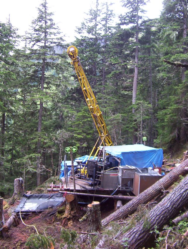
fuel per day. Figure 4-10 shows an operating drill on a Greens Creek drill pad.
For a single season, one drill can usually drill 30,000 feet. A maximum of three drill rigs
will be used for 90,000 feet in one season. If a 90,000-foot program were drilled, eleven
drilling personnel and one helicopter pilot would be committed for approximately five to
six months. Several geologists and core-cutting technicians would also be hired, but
would primarily be logging and cutting core at the Hawk Inlet facility.
Coring operations begin by installing HQ3 (3.77 inch) casing through the overburden and
into the first 20 feet of bedrock. The casing is then set with either bentonite or cement, to
separate the overburden from drilling waters introduced or encountered during the
remainder of drilling. This casing keeps the poorly sorted and unconsolidated sediments
from absorbing drilling water and potentially destabilizing steep slopes.
Once through the overburden, HQ (3.77-inch) coring is completed until the hole is
completed or until ground conditions require reducing to smaller NQ coring (2.97-inch).
Muds and polymers described in section 4.6.4 will be used to stabilize the hole and apply
a ‘filter cake’ of clay on the borehole’s surface. The filter cake limits the amount of
drilling fluids lost to the formation rock (Campbell and Gray 1975).
Drill contractors will be required to submit daily reports detailing activities. For each
shift the drilling crew must also complete an environmental and safety review as detailed
on a pre-shift checklist included as Appendix D. That review includes checking of fuel
tanks, containments, spill kits, fire extinguishers and sumps.
Page | 20Figure 4-10. Typical Diamond Drill Setup at Greens Creek
4.6.4 Materials and Drilling Additives
In order to complete drillholes, bentonite muds and polymers need to be used. These
products stabilize the borehole, remove cuttings and help separate drilling waters from
the surrounding formations and groundwater. Figure 4-11 illustrates how these additives
influence the flow of drilling fluids in a borehole. The right hand side of the borehole
shows water escaping to surrounding rock formations while the left side shows water
returning back to surface for reuse.
Page | 21Figure 4-11. Mud filter cake influencing drill waters.
All of the drilling additives will be environmentally safe and certified by either the
National Sanitation Foundation (NSF) International / American National Standards
Institute (ANSI Standard 40) for use in potable water wells or by the Oslo Paris
Convention list of substances considered to pose little or no risk to the environment
(OSPAR PLONOR 2013). Though no rod lube (used to lubricate and protect the drilling
rods) has been certified by the NSF, only natural, fatty acid, fully biodegradable and/or
non-toxic lubes will be used. The typical drilling additives are listed in Table 4-1.
Page | 22Table 4-1. Typical drilling additives for HGCMC surface drilling programs
Drilling Additives Manufacturer Environmental Certification Chemical family
EZ-MUD DP GOLD® Baroid NSF/ANSI Standard 60 PHPA3
Silicate, spun
N-SEAL™ Baroid NSF/ANSI Standard 60 mineral fiber
POLY-BORE Plus™ Baroid NSF/ANSI Standard 60 PHPA3
QUIK-GEL® Baroid NSF/ANSI Standard 60 Sodium Bentonite
QUIK GROUT® Baroid NSF/ANSI Standard 60 Sodium Bentonite
NSX-Lube® Baroid Not toxic under 40 CFR 372 sec 3131 Blend
QUIK TROL GOLD® Baroid NSF/ANSI Standard 60 PAC4
Soda Ash Baroid OSPAR PLONOR2 Sodium Carbonate
1
Does not meet criteria of 'hazardous waste' as defined by the US EPA (Section 313 of SARA, 1986)
2
Oslo Paris Convention list of substances Considered to Pose Little or No Risk to the Environment
3
Partially hydrolyzed polyacrylamide/polyacrylate (PHPA) copolymer
4
Polyanionic Cellulosic Polymer
While drilling bedrock, the driller keeps 300 to 400 psi fluid pressure on the bit where the
rock is being cut. In normal bedrock drilling conditions, an additive such as QUIK-GEL®
viscosifier is mixed into the drilling water to keep approximately 15-25 pounds of
product for every 100 gallons of water (Baroid 2011a). If the fluid pressure is noticed to
drop or if drilling waters return slower than normal, the driller recognizes that the drilling
fluid is being lost to the formation in what is called a Lost Circulation Zone (LCZ).
As LCZ’s may signify broken or faulted rock, they are immediately addressed by the
driller. Faulted rock may break off onto the drilling rods, trapping the rods in the hole.
Alternatively, the rock could fall out when the rods are pulled to change a worn down
cutting bit, and bridge off the hole so that a new hole must be started. As this is a costly
risk, products such as N-SEAL™ and QUIK-TROL GOLD® are added to lower the water
loss and promote hole stability in LCZ’s. Depending on the nature of the LCZ, up to 70
pounds of N-SEAL™ or 4.75 pounds of QUIK-TROL GOLD® may be added for every
100 gallons of water (Baroid 2012 and Baroid 2011b). These controls are applied until
fluid losses are back to normal.
In the unlikely case where a borehole begins to produce water due to a confined
groundwater system, products such as QUIK GROUT® or cement may be applied to seal
the LCZ or producing formation. If the artesian conditions are not quickly resolved, the
hole is sealed and abandoned. Mechanical packers are kept at the drill to stop artesian
waters until the seal can be made.
Page | 234.6.5 Hole Abandonment
The Alaska Department of Environmental Conservation (ADEC) is the State of Alaska’s
lead agency for Water Quality Standards and has set forth the Alaska Department of
Natural Resources (ADNR) as a lead for determining mine related guidelines. Together
with ADEC, ADNR requires exploration drill programs to abandon boreholes according
to the Hardrock Exploration permit which ADNR issues. In that permit it states:
“All drill hole casings shall be removed or cut off at, or below, ground level. All drill
holes shall be plugged by the end of the exploration season with bentonite hole plug or
equivalent slurry, for a minimum of 10 feet within the top 20 feet of the drill hole. The
remainder of the hole will be backfilled to the surface with drill cuttings. If water is
encountered in any drill hole, a minimum of 7 feet of bentonite hole plug or equivalent
slurry shall be placed immediately above the static water level in the drill hole.
Complete filling of the drill holes, from bottom to top, with bentonite hole plug or
equivalent slurry is also permitted and is considered to be the preferred method of hole
closure during which they are drilled, unless otherwise specifically approved by the
DMLW.” (DNR Alaska)
All HGCMC surface boreholes will be reclaimed according to this guidance by the
ADNR. After the hole has been completed, it will sit for two hours before being sounded
for water. If the water table is encountered, the borehole will be backfilled with drill
cuttings or bentonite to just below the water table. Appropriately sized bentonite hole
plug will be trimmed to the water table using a hose for a minimum depth of 7 feet. The
hole will then be filled with drill cuttings up to 20 feet from surface. All holes will have
the casing removed and be capped with hole plug for the top 20 feet of the borehole.
4.6.6 Drill Site Reclamation
All tools, trash and dimensional lumber will be removed from the drill sites as they are
completed. Non-recyclable lumber will be burned within HGCMC’s Forest Service
prescribed burn pits at the mine site, and trash handled according to HGCMC’s permitted
solid waste disposal plan (see section 5.20).
The drilling platforms will be completely disassembled, with timbers lying either directly
on the ground or resting only two high. If a drilling platform is to be used the following
year, it will not be disassembled. However, no drilling platform will remain constructed
for more than two years.
All sumps and any bare ground will be reclaimed the same season as drilled, regardless of
plans to re-use a drilling platform the following year. Excavated topsoil and organically
enriched topsoil will be placed over the excavation in the reverse order it was removed.
Native vegetation, set aside during excavation, will be used to top the filled excavation.
If an area of bare soil cannot be coved by native soil and vegetation, it will be covered
with seedless straw or coconut fiber (coir). Before 2016, seedless straw was used to
cover bare earth, but the Forest Service has requested in the 2016 Greens Creek Surface
Exploration Decision Memo that coir matting be used instead when available and
Page | 24practical. To follow this guidance, bare earth not overlain with natural vegetation will be
covered with coir matting when available and practical. Seedless straw will only be used
as a last resort. Though no seed mix has been applied to reclaimed drill sites in the past,
HGCMC will reseed disturbed areas with a seed mix if the Forest Service so prescribes.
Fill materials will be mounded slightly (2 to 3 inches) above ground surface to allow for
future settling. Sites will be contoured to prevent erosion and mimic, as closely as
possible, the original topography, but maintain less than 15% grade. Sump geotextile will
be cut back to ground surface, with excess fabric removed from the drill site.
All reclamation shall take place in the year that disturbance was made. The only
exception will be a drilling pad, not including its sump, if it is to be used the following
year. Photos will be taken of each drill site before any disturbance takes place and after
reclamation is finished. Those photos will be submitted to the Forest Service as part of a
yearly activity and reclamation report, to be submitted by December 15 of each year.
Drill sites will be visited two years following reclamation to determine if winter snow
loads or spring melt have damaged reclamation efforts and if invasive plants are present.
If noxious weeds are present, they will be pulled by hand and removed from the site in
garbage bags for landfill disposal. Herbicide will only be used if the weeds cannot be
eradicated by hand pulling and only at the direction of the Forest Service. These visits
will be documented in the yearly activity and reclamation report to the Forest Service.
4.7 Spill Prevention and Waste Disposal
4.7.1 Spill Prevention Control and Countermeasures (SPCC)
HGCMC handles petroleum products according to a professionally engineered and
approved Spill Prevention Control and Countermeasure plan as required by the Code of
Federal Regulations (CFR) Title 40 Section 112. Though petroleum handling precautions
and countermeasures are described in the SPCC plan, the following discussion addresses
those aspects of the plan directly applicable to the exploration plan.
4.7.2 Fuel transport and storage
Jet-A helicopter fuel is transported to the mine in 6,341-gallon portable tanks of US DOT
Type IM 101. One tank is kept near Hawk Inlet and another is stored closer to the mine
portal at the ‘860’ laydown as shown in Figure 4-12. The helicopter fuels directly from
these two sites. The locations were chosen in order to maximize efficiency in mobilizing
crews from the man camp at Hawk Inlet and drilling supplies stored at the ‘860’ laydown
area. Both tanks and pumps have secondary containment made with chemically resistant
polyethelyne liners. Spill response kits are kept next to the pumps.
Type 2 Diesel fuel for the drill and water pumps is managed by mine personnel according
to the SPCC plan. The fuel is stored in Greens Creek Mine managed tanks and
transported using their fueling “lube” truck. At the ‘860’ laydown, 30-gallon, double
walled, aluminum, flyable fuel tanks will be stored in secondary containment. The lube
Page | 25You can also read